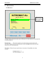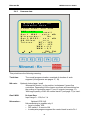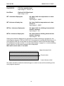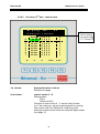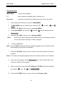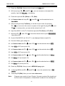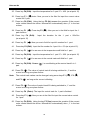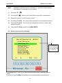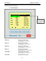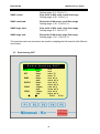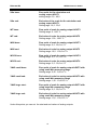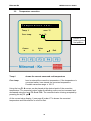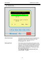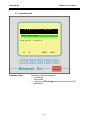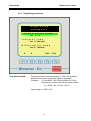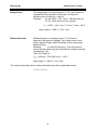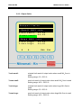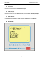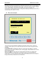
1
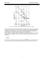
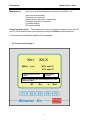
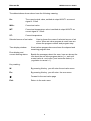
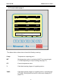
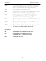
Nitromat - Kn MESA Electronic GmbH 82538 Geretsried – Gelting Leitenstraße 26 Tel: 08171 / 7693-0 FAX: 08171 / 7693-33 E-M ail: m e sa @ me s a-g m bh. c om Ho me pa g e: www.m e sa -g mb h. co m measurement – controlling – automation - measurement – controlling – automation - measurement – controlling – automation User manual Nitromat-Kn MESA electronic GmbH 1. Basic ..................................................................................................................... 5 2. Menu overview ..................................................................................................................... 6 2.1 Main menu ..................................................................................................................... 6 2.2 Current values page 1: ...................................................................................................... 7 2.3 Current values page 2: ...................................................................................................... 9 2.4 Set value menu ................................................................................................................ 11 2.4.1 1st page W-prog.menu ........................................................................................... 13 2.4.2 2nd . page W-prog. menu ........................................................................................ 14 2.4.3 Common data......................................................................................................... 15 2.4.4 Set values............................................................................................................... 17 2.4.4.1 Set values 1st part ...................................................................................... 17 2.4.4.2 Set values 2nd part , control track ............................................................. 18 2.4.5 Example for set value program ............................................................................. 19 2.5 Service menu and it’s submenu...................................................................................... 24 3. Scale Analog IN ................................................................................................................... 25 3.1 Scale Analog OUT............................................................................................................ 26 3.2 Temperature correction................................................................................................... 28 3.3 Process data ................................................................................................................... 29 3.4 Regulator data ................................................................................................................. 30 3.4.1 Regulating parameters .......................................................................................... 31 3.4.2 Output limits........................................................................................................... 33 3.5 Calculation ................................................................................................................... 34 3.6 Probe purging .................................................................................................................. 34 3.7 Serial interface ................................................................................................................. 34 3.8 DIP-switches ................................................................................................................... 34 3.9 Calibration (HW) .............................................................................................................. 35 4. Alarms and warnings .............................................................................................................. 35 4.1 Error menu example ........................................................................................................ 36 5. Nitromat-Kn outputs ............................................................................................................... 37 5.1 Nitromat-Kn digital outputs............................................................................................. 37 2 Nitromat-Kn MESA electronic GmbH 5.2 Analog outputs of Nitromat-Kn ....................................................................................... 38 6. Inputs of Nitromat-Kn ............................................................................................................. 38 6.1 Digital inputs of Nitromat-Kn .......................................................................................... 38 6.2 Analog inputs of Nitromat-Kn ......................................................................................... 39 Appendix A: Using the DIP switches ............................................................................................. 40 Appendix B: Connector terminal marking ..................................................................................... 41 Appendix C: Nitromat-Kn connector position ............................................................................... 42 3 Nitromat-Kn MESA electronic GmbH Introduction Nitriding is thermo-chemical process for hardening the surface layer of steel workpiece. Nitriding is applied in order to increase the resistance to wearing and corrosion and to improve the dynamical hardness of steel parts. The surface layer provide the resistance to wear and corrosion while the diffuse layer located below, preserve hardness. Process temperature during nitriding is between 450ºC and 580ºC while it last from 1 up to 100 hours. Interconnect layers, made in gas nitriding process, are composed of intermetalic connection of iron and nitrogen (ε- and γ'- iron nitrides) which, depending of process duration, can achieve depth of 10...30 µm and can have high point of hardness with low brittle characteristic. But molding of this layer can be completely avoided. A diffusion zone can be found below which achieve up to 0.8mm in depth into material. Here the nitrogen is diffusing into internal iron structure and with alloying component like Cr, Mo, Ti, Al, V creates special nitrides. This special nitrides are very important for high hardness and wear resistance of alloyed materials. Carburizing is thermo-chemical process for doping and hardening the surface layer of workpiece. Carburizing is performed in gas atmosphere at temperature between 500ºC and 630ºC in mixture of gases which can release nitrogen (per example ammonia) or carbon (per example carbon dioxide). The aim is to increase the resistance to wearing and corrosion of low and medium alloyed steels. Dissolution of ammonia is performed in correlation with the following formula 3 H2 2 The nitriding characteristic number is known as NH 3 KN N p NH 3 p H2 3 2 In case of pure nitriding, the nitriding characteristic number can be calculated from the degree of dissolution of ammonia i.e. from the quantity of hydrogen in furnace. The figure 1. shows the conditions for originating the specific phases of iron nitrides versus nitriding characteristic number and temperature. This diagram could be well implemented for low alloyed steels. We would like to shortly present the basics of Nitromat-Kn functions. For determination of H2 in furnace atmosphere the H2 probe is used. Nitromat-Kn is using the signal from this probe and calculating the nitriding characteristic number Kn and compares it with set value. In case of variation an adequate signal is sent to the mass-flow controller for ammonia which increase or decrease the ammonia flow. The flow is being tuned until the calculated Kn value is not equal to the setup Kn value. 4 Nitromat-Kn MESA electronic GmbH figure 1. The conditions for originating the specific phases of iron nitrides The current data about the flow Nitromat-Kn is getting from the mass-flow controllers which gives current signals 4...20mA. Thanks to the free input scaling Nitromat-Kn is capable to operate with various flow meters. Calculated results are interpreted as current signal 4...20mA and a free scale choose is also possible. NH3 flow can be controlled with two mass-flow controllers with different size. In order to provide such capability Nitromat-Kn dispose separate parameters for controller adjustment. 1. Basic In each menu, except the main menu, there is key F5 EXIT. If you, at some point, do not know where you are just keep pressing F5 until you came back in main menu. 5 Nitromat-Kn 2. MESA electronic GmbH Menu overview 2.1 Main menu NITROMAT-Kn MAIN MENU Normal – Display Set values Maintenance (RESTART) The selection bar is moving by cursor keys F1 and F2 Cursor Disp lej The figure above shows the main menu of Nitromat –Kn from where you can reach the following subpoints: Normal view: This view is spited in two sides showing current values and set values. Beside this, here are shown the current messages about the errors and about the current operating state. Set values: Below this menu point there is overview of all available set values sources: Constant value 1 – 5 Set value programs 1 - 99 6 Nitromat-Kn Maintenance: MESA electronic GmbH Here you can find settings and correction of controller, etc. Input and output scaling Temperature correction Gas-treatment activation temperature Initial gas quantity for treatment Controller setting DIP switch setting Choosing menu point: The selection bar can be moved by pressing cursor keys F1 and F2 to the desired menu point and then the keys F4 Disp should be pressed. In the following text different display will be explained: 2.2 Current values page 1: Kn= WKn= XX,X xx,x WT= xxxx°C XT= xxxx°C Selected source of set value Time display window Place for displaing the error mesages and curent operating status W Err 7 Exit Nitromat-Kn MESA electronic GmbH The abbreviations shown above have the following meaning: Kn: The current actual value, emitted at output AOUT1 as current signal 4...20mA WKn: Current set value WT: Current set temperature value is emitted at output AOUT2 as current signal 4...20mA XT: Current temperature Selected source of set value: Time display window: Error display and current working status: Here is shown the name of selected source of set value. When set value program is used, here are shown the program number and program step. At set values program here are shown the elapsed and remaining program time Beside the messages about the error, here are shown the info about the set value program status (i.e. „wait until current value is = set value“) and controller status (i.e. „regulation is normal ->“). Key marking: W: By pressing this key you will enter the set value menu Err: By pressing this key you will enter the error menu : Forward to the next value page Exit: Return to the main menu 8 Nitromat-Kn MESA electronic GmbH 2.3 Current values page 2: Comp WT xx °C XT xxx Y xxx °C YNH3 NH3 xx % x,xx x,xx m³h XH2 xx,x % WN2 xx,x XN2 xx,x m³h SGas WCO2 xxx m³ XCO2 xx,x xx ,x m³h Place for displaing the error mesages and curent operating status W Err Exit The abbreviations shown above have the following meaning: Comp: Temperature comparing point WT: Set temperature value is emitted at AOUT2 as current signal 4...20mA depending on output scaling (see page 17) XT: Current temperature value Y: Calculated opening degree of regulating device. YNH3: Calculated opening degree of regulating device translated into m3/h NH3. Scaling could be found in menu point Analog OUT (page 27). 9 Nitromat-Kn MESA electronic GmbH XNH3: Current ammonia flowing in shown in standard cubic meters per hour. It is calculated based on the current signal from the flow meter (4...20mA) and on the input scaling (see page 26) XH2: Current hydrogen concentration in furnace WN2: Set value of nitrogen is emitted at output AOUT3 as current signal 4...20mA and in proportion with scaling (see page 27 ) XN2: Current nitrogen flow in standard cubic meters per hour. It is calculated based on the current signal from the flow meter (4...20mA) and on the input scaling (see page 25) SGas: Counter of gas quantity. Adds received quantities of NH3 , N2, and CO2. WCO2: Set value of carbon dioxide emitted at output AOUT4 as current signal 4...20mA (see page 27) XCO2: Current carbon dioxide flow in standard cubic meters per hour. It is calculated based on the current signal from the flow meter (4...20mA) and on the input scaling (see page 25). Key markings: W: By pressing this key you enter the set value menu Err: By pressing this key you enter the error menu Return to the page 1 of the current value menu Exit: Return to the main menu 10 Nitromat-Kn MESA electronic GmbH 2.4 Set value menu S E T V A L U E Fix-W1 M E N U xx,x / xx,x / xx,x / xx,x / xx,x / xxxx xxxx xxxx xxxx xxxx W-prog. No.: xx W-prog. edit Fix-W2 Fix-W3 Fix-W4 Fix-W5 W - p r o g . The selection bar is moving by cursor keys F1 and F2 s t o r e d ! Strt Edit Exit The arrow marks the active source of set value value Appears when memorising the set value program The abbreviations shown above have the following meaning: Fix-W1 – Fix-W5: Fix set values 1-5. The following numbers shows Kn-set value and temperature set value W-prog No.: Shows the chosen set value program number. This set value program can be edited or run. Edit W-program: Under W-prog.No.: Chosen program is available after choosing this menu point and after pressing F4 Edit key for editing the program. Starting the set value source: With cursor keys F1 and F2 the selection bar should be set to the desired source of set value. Then, with key F3 Strt, start the source for set value. 11 Nitromat-Kn MESA electronic GmbH Setting the number of set value programs: Using the selection bar you should choose menu point W-prog.No. Then, with F4 Edit key activate the number of program for editing. Keys F1-F5 now have different function: F1: moves blinking cursor one step in right F2: Increments the cursor value for 1 F3: Decrements the cursor value for 1 F4: Enter key, which accepts the new program No. F5: Exit key, which stops the editing process and keeps the old program Changing the set value program: Selection bar should be set to menu point Edit W-program. Then by pressing F4 Edit key activate the chosen program for editing 12 Nitromat-Kn 2.4.1 MESA electronic GmbH 1st page W-prog. menu W - P R O G . W-p rog . – M E N U No .: xx C o m m o n d a t a S e t v a l u e s Do you want to edit a W-program? YES NO With key F5 No you can reach to 2nd display of set value menu where you can check the set value program without any change. With key F2 Yes you can enter u display 2 of set value menu and you can change the data. 13 Nitromat-Kn 2.4.2 MESA electronic GmbH 2nd . page W-prog. menu W - P R O G . W - p r o g . C o S e W C o – M E N U N o . : The selection bar is moving by cursor keys F1 and F2 x x m m o n d a t a t v a l u e s p r o g . e r a s e p y f r o m : x x The number of choosen program Possible range 1-99 Ed it Ex it If you move the selection bar by key F1 and if chosen program is running as a source of set value then the following message will appear: RUNNING! Changes are valid only for this program running! This means that changes will take effect only for current program running and will be lost after program restart. At the „current value display 1“ (page 7) in field „Selected source of set value” there is an description of changed program. W-Pr(m) x-x The letter m in brackets means modification. At the new program start the changes are lost and the original program is being executed. After choosing the adequate menu point with keys F1 and F2 , by pressing the key F4 Edit you can enter the adequate menu or execute the desired action. 14 Nitromat-Kn 2.4.3 MESA electronic GmbH Common data W - p r o g . N o . : C o m m o n l d a t a T o t a l N H 3 G N G K T t i m e : x x h x x x x m r a t e s m a l l as 1 W N 2 : x x x , x m³/h i t r o c a r b u r . : N o as 2 WCO2 : xx,x m³/h N - O f f s e t : + x , x o l e r a c . W T + : 1 0 °C W T - : 1 0 °C WKN +: 0,3 WKN -:0,3 Ed it Ex it Edit Exit This points have the following meaning: Total time: NH3 rate: The overall program duration consisted of duration of each segment (for segments see pages 17, 18) Optional choice large / small Nitromat-Kn should , by its position, be between 2 mass flow controllers. Depending of the chosen one there will be switched on the scaling of inputs(see page 17) and Y-outputs (see page 17). With large quantity of NH3 the control track E (see page 17) is used. Gas1 WN2: N2 input flow Input range 0....100,0 m³ / h Nitrocarbur.: Optional YES / NO Nitrocarburizing is possible only if: here is chosen YES DIP switch 1-2 is set to ON In adequate program segment the control track is set to D=1 15 Nitromat-Kn MESA electronic GmbH Gas2 WCO2: CO2 flow quantity input Input range: 0...30,0 m³ / h Kn-Offset: Optional Kn Offset input Input range: ± 9,9 WT+ tolerance display bar: the upper limit for temperature set value tolerance Input range 0...200ºC WT- tolerance display bar: the lower limit for temperature set value tolerance Input range 0...200ºC WTKn+ tolerance display bar: the upper limit for nitriding characteristic number tolerance Input range 0...9,9 WTKn- tolerance display bar: the lower limit for nitriding characteristic number tolerance Input range 0...9,9 Setting the tolerance display bar is important for further switching in program for the next program segment. With set X-Bit (X=1) the program is waiting with switching on to next segment until the current and set value at least are close to set tolerance range for temperature and Kn number. In current value display 1 (page 8) , in current working status window, the following message will be displayed: Wait until current value = set value. Upper tolerance limit Current value Lower tolerance limit Set value should be inside the hatched region in order to execute the switching to the next program segment. 16 Nitromat-Kn 2.4.4 MESA electronic GmbH Set values Set values 1st part 2.4.4.1 The set values display is divided in two parts. First part looks like the follows: W - p r o g . N o . : x x S e t v a l u e duration 0h 0m 0 1 2 3 4 5 6 7 WKn 0,0 0,0 0,0 0,0 0,0 0,0 0,0 0,0 0h 0m 0h 0m 0h 0m 0h 0m 0h 0m 0h 0m 0h 0m °C 0 0 0 0 0 0 0 0 Ed it The selection bar is moving by cursor keys F1, F2 and F3 Ex it By pressing the key F1 the selection bar goes to columns WKn and ºC. Further pressing leads to the second page for current value display. 1st column program segment number 2nd column segment duration in hours and minutes Hour input range: 0...99h Minutes input range: 0...59min 3rd column WKn Characteristic set value number Input value: 0...50,0 4th column ºC setvalue for temperature Input value: 0...1200ºC 17 Nitromat-Kn 2.4.4.2 MESA electronic GmbH Set values 2nd part , control track W - p r o g . N o . : x x C o n t r o l t r a c k s Duration 0h 0m 0h 0m 0h 0m 0h 0m 0h 0m 0h 0m 0h 0m 0h 0m 0 1 2 3 4 5 6 7 A 0 0 0 0 0 0 0 0 B 0 0 0 0 0 0 0 0 C 0 0 0 0 0 0 0 0 D 0 0 0 0 0 0 0 0 Ed it X 1 1 1 1 1 1 1 1 The selection bar is moving by cursor keys F1, F2 and F3 Ex it 1st column: Segment duration in hours See previous page 2nd column: control tracks A – D Setting option: Set=1 Switched off=0 Function of control track A – C can be freely chosen (i.e. Fast cooling on, signal, proper segment is running). The control track D is marked as „Carburizing ON“ Setting the control track switch on adequate digital output (see page 17) 18 Nitromat-Kn 3rd column: MESA electronic GmbH X-bit Setting option: set=1 Not set=0 Whet X-bit is set the switching on to the next program segment will wait until the current and set values for temperature and Kn are inside the set tolerance range (see Common data, page 16). If the set value and current value are not in tolerance range and if there should wait, then the programmed segment duration is exceeded. 2.4.5 Example for set value program Caution: The arrow shown on the display, in set value menu, shows which kind of set value is chosen. If you change already started program then that change will have effect only for current program running and after that will be lost. If you want to input a program and to memorize it than this program should not be started during the input. The program number used here are random chosen. Instructions for starting and running the program for set values At set value program the first and the last segment with special features. The set value program can run when: The temperature overrun appear (in example 430ºC) 1*. In opposite, the program is waiting for it (on figure 1, with standard display, will appear the message “Wait for StartTmp.”. Input IN0 is OFF (controller blocking / program stop) Inside this waiting phase it is not possible to switch on the program over the digital input IN1 (further program switching) e.g. the starting conditions must be fulfilled . Digital output OUT6 (W-prog. is running) is not switched on. 1. Program segment is step “Temperature regulation” (setting the temperature in the furnace). During this step the digital output OUT9 (current value is in tolerance range) is not switched on although the temperature and C level are inside the tolerance range. Output OUT6 (W-prog is running) is switched on. The next segment is running normally. When X-bit is set there should be waited for current value and set value to be inside the tolerance range. When the program reaches further regulation is performed with the latest values fro temperature and Kn number. Digital output OUT6 (W-prog is running) is switching off. Control tracks, which are set in the latest program segment, remain switched on. Detailed description of program input (step by step). 19 Nitromat-Kn MESA electronic GmbH Sign description: MAIN MENU current menu heading F1 the key below the display (here Function key 1) Set values move the cursor with keys till this sub-point. (here „set value“) 1. After switching the device you will be in MAIN MENU. 3. In MAIN MENU set the selection bar with keys F1 () and F2 () to Set values press key F4 (Disp). Now you are in set value MENU 4. In set value MENU with keys F1 () and F2 () set the selection bar to 2. W-prog edit 5. Press key F4 (Edit) . Now you are in W-prog. MENU. Note: Since this is about important input, Nitromat-Kn is now asking a question, do you really want to change or make a program. 6. Press key F2 (Yes). Note: If key F5 (NO) is pressed, then the existing programs can be controlled. Input and changing of values are not possible. 7. Press key F4 (Edit). Now you are in mode for input the number for set value program. Note: For creation the example program choose the number which is not occupied. 8. Now enter the program number W-prog. No. 01 or other. All the rest of the inputs are related to this program. 9. After you finish the input exit with F4 (Enter) or F5 (Exit). Move the selection bar with F1 () and. F2 () to Common data. 10. Press key F4 (Edit). Now you are in input mode Common data 20 Nitromat-Kn MESA electronic GmbH 11. Press key F4 (Edit). Now you are in input mode NH3 rate. 12. With arrow keys F2 () and F3 () you can increase or decrease NH3 quantity. Input the NH3 rate = increasing 13. Finish the input with F4 (Enter) or F5 (Exit). 14. In Common data with keys F1 () and F2 () set the selection bar to Gas1WN2. 15. After pressing the key F4 (Enter) you will be in input mode. By pressing F1 () you can move the cursor one place to the right. By keys F2 () and F3() , in some points, you can set the values from 0 to 9. 16. Input Gas1WN2 = 0,0 m3/h. Finish the input with F4 (Enter) or F5 (Exit). 17. With keys F1 () and. F2 () move the selection bar to point Nitrocarbur. Here select NO. 18. At point Gas2WCO2: set 10,0 m3 / h ( as displayed below at point 15). 19. Point Kn-Offset: gets setting 0,0. 20. In Common data with F1 () and. F2 () set the selection bar to WT+. 21. Input WT+=10ºC (as at point 15). 22. In Common data with F1 () and. F2 () set the selection bar to WT-. 23. Input WT+=10ºC (as at point 15). 24. In Common data with F1 ()and. F2 () set the selection bar to WKn+. 25. Set WKn+=0,3 (as at point 15). 26. In Common data with F1 ()and. F2 () set the selection bar to WKn-. 27. Set WKn-=0,3 (as at point 15). 28. Press key F5 (Exit). Now you are in MENU W-prog again. 29. In W-prog MENU with F1 () and F2 () move the selection bar to Set values. 30. Press key F4 (Edit). Now you are in set value menu. Note: Program may consist of max 23 parts. One part consist of the length and the end value of temperature, characteristic number Kn for nitriding and 21 Nitromat-Kn MESA electronic GmbH control tracks which, at the beginning of this part, can be switched on and off. Starting set value of one part is the last set value of the previous part. If the control track has the value „1“, then it is switched on or if the control track has value „0“, it is switched off. If you move the selection bar, with F2 () and F3 () , across the table above the edge of the display, then you will automatically go to the next display page. The table with values for the above displayed program flow: 0 1 2 3 4 5 6 7 8 9 Duration 0h 1m 0h 1m 7h 0m 0h 1m 0h 0m 0h 0m 0h 0m 0h 0m 0h 0m Kn 29,0 5,0 5,0 5,0 0,0 0,0 0,0 0,0 0,0 °C 430 620 620 20 0 0 0 0 0 ABCD 0 0 0 0 0 0 0 0 0 0 0 0 0 0 0 0 0 0 0 0 0 0 0 0 0 0 0 0 0 0 0 0 0 0 0 0 X 0 1 1 1 1 1 1 1 0 Note: The paths are freely available Note: Current value control Nitomat-Kn can, during the program running, control if the current measured values are in tolerance range which is entered in Common data. If the control track „X“ is switched on, in the last table column („1“), then the flow of the program time is stopped until the current values are not again in the defined tolerance range. At some processes this function is not desirable and can be avoided by turning off the control track („X“). 31. Press key F4 (Edit). Input the duration of the 0. part = 00h01m. (as at point 15) 32. Press key F1 (). Now you are in field for input Kn number for 0. part. 33. Press key F4 (Edit). Input the Kn number for 0.part. Kn = 29,0 (as at point 15). Finish the input by pressing the key F4 (Edit). 34. Press key F1 () . You are now in the temperature edit field for 0. part. 22 Nitromat-Kn MESA electronic GmbH 35. Press key F4 (Edit). Input the temperature for 0. part ºC = 430. (as at point 15) 36. Press key F1 () twice. Now you are in the field for input the current value control for 0. part. 37. Press key F4 (Edit). Using the key F5 (No) answer the question if the current value control should be active. Nitromat-Kn automatically store „0“ in the last column. 38. Press key F1 (). Press key F2 (). Now you are in the field for input the 1. part duration. 39. Press key F4 (Edit). (as at point 15) Input the duration for the 1. part = 00h01m 40. Press key F1 (). Now you are in field for input Kn number for 1. part. 41. Press key F4 (Edit). Input the Kn number for 1.part. Kn = 5,0 (as at point 15). 42. Press key F1 ().You are now in the temperature edit field for 1. part. 43. Press key F4 (Edit). Input the temperature for 1. part ºC = 620. (as at point 15) 44. Press key F1 ().You are now in the control track edit field for 1. part. 45. Press key F4 (Edit). Cursor ( part. ) is now blinking at the control track A in 1. 46. Press F3 (). The value of control track A is being switched to „1“ and the cursor is moving one place further. Note: The control track values can be changed using arrow keys F1 () , F2 () and F3 () .as long as the cursor is blinking. 47. Press F3 ().The value of control track B is being switched to „1“ and the cursor is moving one place further. 48. Press key F4 (Enter). The input for control track for 1. part is finished . 49. Press key F1 (). Now you are in the field for input the current value control for 1 part 50. Press key F4 (Edit). Using the key F5 (Yes) answer the question if the current value control should be active. Nitromat-Kn automatically store „1“ in the last column. 23 Nitromat-Kn Note: MESA electronic GmbH Standard, in the last column, is entered “1“. Point 46 can be skipped if the change of current value is not needed. 51. Press key F1 () . 52. Press key F2 (). Now you are in the field for input the 2. part duration. 53. Repeat the points 31 to 48 for parts 2 and 3. 54. Press key F5 (Exit) . The current value program is now completely entered. 55. Press key F5 (Exit) . The current value program is stored in memory with program number. 56. Using key F5 (Exit) go back to the MAIN MENU. 2.5 Service menu and it’s submenu M AI NT E N ANC E M E NU Scale Ana lo g IN Scale Analog OUT The selection bar is moving by cursor keys F1 and F2 Temperature corr. Process data Controller data Calcula tion Probe purging Seria l interface Switch settings Calibration (HW) Edit Ex it By pressing keys F1 and F2 you can move the selection bar to desired submenu points. Pressing the key F4 (Edit) will activate the inversed represent submenu point. 24 Nitromat-Kn MESA electronic GmbH Detailed sub-menu description: 3. Scale Analog IN S c a l e A n a l o g I N XH2 base: xx,x % end: xxx,x% XN2 base: xx,x m³h end: xxx,x m³h XCO2 base: xx,x m³h end: xxx,x m³h XNH3 s base: xx,x m³h end: xxx,x m³h XNH3 l base: xx,x m³h end: xxx,x m³h Edit Exit XH2 base: Zero point of H2 scale Setting range: 0,0...90,0 % XH2 end: End point of H2-scale Setting range: 10,0...100,0 % XN2 base : Zero point of N2 scale Setting range: 0,0...90,0 m³ / h XN2 end: End point of N2-scale Setting range: 10,0...100,0 m³ / h XCO2 base: Zero point of CO2 scale Setting range: 0,0...20,0 m³ / h XCO2 end: End point of CO2-scale 25 The selection bar is moving by cursor keys F1 and F2 Nitromat-Kn MESA electronic GmbH Setting range: 3,0...30,0 m³ / h Zero point of NH3 scale, small flow range Setting range: 0,00...9,00 m³ / h XNH3 s base: XNH3 small end: End point of NH3-scale, small flow range Setting range: 1,00...10,00 m³ / h XNH3 large start: Zero point of NH3 scale, large flow range Setting range: 0,0...90,0 m³ / h XNH3 large end: End point of NH3-scale, large flow range Setting range: 10,0...100,0 m³ / h The particular start and end values are used for adapting the Nitromat-Kn with different flow meters. 3.3 Scale Analog OUT S c a l e XKN WT WN2 WCO2 YNH3 YNH3 A n a l o g base: end: base: end: base: end: base: end: s base: end: l base: end: O U T xx,x xx,x xxxx °C xxxx °C xx,x m³ h xxx,x m³ h xx,x m³ h xxx,x m³ h x,xx m³ h xx,xx m³ h xx,x m³ h xxx.x m³ h Edit Exit 26 Nitromat-Kn MESA electronic GmbH XKn base: Zero point for Kn calculation and analog output AOUT1 setting range: 0,0...40,0 XKn end: End value of the scale for Kn calculation and analog output AOUT1 Setting rage: 10,0...50,0 WT base: Zero point of scale for analog output AOUT2 Setting range: 0...900 °C WT end: End value of scale for analog output AOUT2 Setting range: 100...1200 °C WN2 base: Zero point of scale for analog output AOUT3 Setting range: 0,0...90,0 m³ / h WN2 end: End value of scale for analog output AOUT3 Setting range: 10,0...100,0 m³ / h WCO2 base: Zero point of scale for analog output AOUT4 Setting range: 0,0...27,0 m³ / h WCO2 end: End value of scale for analog output AOUT4 Setting range: 3,0...30,0 m³ / h YNH3 small base: Zero point of scale for analog output AOUT5 with using small NH3 measuring range Setting range: 0,00...9,00 m³ h YNH3 small end: End value of scale for analog output AOUT5 with using small NH3 measuring range Setting range: 1,00...10,00 m³ / h YNH3 large start: Zero point of scale for analog output AOUT5 with using large NH3 measuring range Setting range: 0,0...90,0 m³ / h YNH3 large end: End value of scale for analog output AOUT5 with using small NH3 measuring range Setting range: 10,0...100,0 m³ / h Under this points you can set the start and end values of analog outputs 27 Nitromat-Kn 3.2 MESA electronic GmbH Temperature correction T e m p e r a t u r e Temp. 1 c o r r . xxxx °C Corr. temp. xx xx °C Cursor is blinking at the first position Cursor Value Exit Temp1 shows the current measured real temperature Corr. temp here is entered the correction temperature. If the temperature is corrected earlier, here stands the corrected temperature. Possible correction range: ± 100 °C Using the key F1 cursor can be placed at the desired point of the correction temperature. The numerical values under the blinking cursor can be increased and decreased using the keys F2 and F3 . The corrected value is being accepted by pressing the key F4 . At the current value display 1 (see page 8) under XT is shown the corrected temperature and Nitromat-Kn is count on that. 28 Nitromat-Kn MESA electronic GmbH 3.3 Process data P r o c e s s d a t a Gas release temp. xxx °C I n i t i a l xxx m³ g a s f l u s h Edit Exit Gas release temp: Gas treatment is being performed from this furnace temperature. Besides, the set N2 and CO2 gas quantities and the Y value are held at 0. Setting range: 390...1100 °C Initial gas flush: Gas quantity which after starting the program must enter into furnace to make the atmosphere, thus the regulation. The initial gas treatment follows after the program step for temperature regulation and ends when the overall measurement of gas meter reach the value already set here. The initial gas flush do not works with fix set value (Fix-W1 – Fix-W5) 29 Nitromat-Kn MESA electronic GmbH 3.4 Regulator data R e g u l a t o r d a t a PID settings O u t p u t Regulator data: l i m i t s Edit Exit The menu point has subpoints: PID settings Outputlimits In sub-point PID settings are held the regulator PID parameters 30 Nitromat-Kn MESA electronic GmbH 3.4.1 Regulating parameters R e g u l a t i n g p a r a m e t e r P r o p o r t i o n a l xxx % / Kn b a n d I n t e g r a l t i m e xxx % / (Kn*min) D i f f e r e n t i a l b a n d xxx % / (Kn/min) Proportional band: Ed it Ex it Proportional part of correcting value Y. Only the deviation between the current and the set value is important. Example: It is set 400% / Kn. With deviation of 0,2 Kn between the current and the set value results: YP = 400% / Kn * 0,2 Kn = 80 % Input range: 0...999 % / Kn 31 Nitromat-Kn Integral time: MESA electronic GmbH The integral part of correcting value Y. For I-part value it is important the time duration of deviation. As long the deviation last as high the I –part is. Example: It is set 100% / ( Kn * min ). With deviation of 0,1 Kn, which last for 5 min, results: YI = 100% / ( Kn * min ) * 0,1 Kn * 5 min = 50 % Input range: 0...999 % / ( Kn * min ) Differential band: Differential part of correcting value Y. For D-part is important the speed of change. The rising current value gives negative D-part while the falling current value gives positive D-part Example: It is set 25%/(Kn/min). From the last but one to the last measuring the characteristic number has bee increased by 1Kn. Then, the D-part is: YD= -(1Kn/min * 25%/(Kn*min)) = -25 % Input range: 0...999 % / ( Kn / min ) The overall correcting value is being calculated upon three separated values: Y = YP + YI + YD 32 Nitromat-Kn MESA electronic GmbH 3.4.2 Output limits O u t p u t l i m i t s - S m a l l N H 3 Y-mi n Y-max - H u g e small: small: N H 3 Y-mi n huge: Y-max huge: r a t e xx,x % xx,x % r a t e xx,x % xx,x% Ed it Ex it Y-min small: minimal limit reach of output value when small NH3 flow is used Setting range: 0,0...50,0 % Y-max small: max limit reach of output value when small NH3 flow is used Setting range: 40,0...100,0 % Y-min huge: minimal limit reach of output value when huge NH3 flow is used Setting range: 0,0...50,0 % Y-max huge: max limit reach of output value when huge NH3 flow is used Setting range: 40,0...100,0 % 33 Nitromat-Kn MESA electronic GmbH 3.5 Calculation Parameters in this submenu should not be changed. 3.6 Probe purging Parameters in this menu point do not have any function. Do not make any changes. 3.7 Serial interface In this submenu parameters can not be changed. Serial interface is not planned. 3.8 DIP-switches N I T R O M A T - M ( P l a n t c o n f i g . D I P - s w i t c h T E M P 1 C - g a s . C - c a r r i e r I / O e x p a n d . Al a r m - Q u i t W - P r g . e d i t Maintenance V x . x ) : : : : : : : Exit 34 Nitromat-Kn MESA electronic GmbH In this menu you can check settings of DIP-switch placed at the back of the controller. The following display can appear (depending of switch positions). When the switch is In position appears The display DIP 11 DIP 11 DIP 12 DIP 12 DIP 13 DIP 13 DIP 15 DIP 15 DIP 16 DIP 16 DIP 17 DIP 17 DIP 18 DIP 18 ON OFF ON OFF ON OFF ON OFF ON OFF ON OFF ON OFF TEMP1 TEMP1 C-gas path C- gas path C-carrier C- carrier I / O expand. I / O expand. Alarm-Quit Alarm confirmation W-Prg.edit W-Prg.edit maintenance maintenance PTRH-Pt NiCr-Ni YES NO Endogas CO2 YES NO automat. manual locked permitted locked permitted Take note: Generally all DIP-switches which are not used , must be in OFF position IF I/O expansion do not exist then DIP switch 15 must be in OFF position. In the first line of this manual the software version number can be found. 3.9 Calibration (HW) In this menu point are located the calibrating data for inputs and outputs. The data can not be changed. 4. Alarms and warnings Nitromat-Kn makes difference between the alarm and the warring. Alarms represent hard disturbances so the device functioning is not guaranteed anymore. i.e. as alarm will be treated: Thermocouple damage When the alarm is activated, from the safety reasons, all the regulating devices (valves) are being closed. Warnings are not representing dangerous deviations from normal working conditions. i.e. power failure. 35 Nitromat-Kn MESA electronic GmbH Warnings and alarms are appearing in adequate windows as part of current display 1 and 2. They are also memorized in error menu. This menu can be reached, through current value display, by pressing the key Err (see page 8 and page 10). Confirmation of warnings and errors is being done manually (DIP-switch S16 OFF) or automatically (DIP switch S16 ON). 4.1 Error menu example E R R O R T C 1 D I S P L A Y ( T EM P1 ) b re a k Alarm caused: T e rmo e l . 1 o š t e će nj e Quit Alarm OFF. Exit The errors are shown between heading and message „Alarm used“. Under the message „alarm used“ you can find a info about the error which caused the alarm activation. Key F2 Alarm Off is resetting the alarm for control track (see page 17) causing switching off of the alarm indicators (horn, blinking light). Reports about error on the page are being stored. With key F1 Quit you can erase error reports and reset alarm for control track. With key F5 Exit you will go back to the display where you pressed ERR-key. If DIP switch 1-6 is set to ON (automatic alarm confirmation) then the error report is being automatically erased after error elimination. 36 Nitromat-Kn MESA electronic GmbH 5. Nitromat-Kn outputs 5.1 Nitromat-Kn digital outputs Nitromat-Kn has in total 2 digital outputs (open collector type). In order to be able to use them you will need external 24VDC power supply. Output connection can be found in appendix C. Detailed output description: - Probe purging not used in Nitromat-Kn - Gas treatment activation In menu point for gas treatment activation (see Service menu, page 17), if the set temperature is overflowed then the output is being turned off. - Control track D Carburizing ON, in common data (see page 16) and in control tracks (see page 17) the switching on and off is performed. - Control track E decision if the large or small flow quantity will be used. Can be set based only on common program data. - Current value program is running Output is switched on as soon as the current value program is activated and the start temperature is reached. - Alarm is turned on if fatal error occurs (i.e. thermocouple damage) - Control track C Control track can be set from the control track column (see page 17) Control track is not being temperature controlled meaning that it can be involved into activating temperature. Thus, external blocking can be necessary. Current value in tolerance range the output is being switched on as soon as the variation between the set and the current value is in set tolerance range. At the current value display 1 (page 8) the working status is displayed regulation normal ->. - Control track A see control track C - Control track B see control track C 37 Nitromat-Kn MESA electronic GmbH 5.2 Analog outputs of Nitromat-Kn Nitormat-M has 5 analog outputs. Each of them is emitting current 4...20mA with max resistance 500ohm. Output scaling can be done in menu point Scale Analog out in service menu (page 17). Detailed output description: output AOUT1 AOUT2 AOUT3 AOUT4 AOUT5 6. emitting terminal + Characteristic 27 Nitriding number Set temperature 26 Set N2 value 20 set CO2 value 12 Correction value Y 11 terminal 9 9 9 9 9 Inputs of Nitromat-Kn 6.1 Digital inputs of Nitromat-Kn Nitromat M has 3 digital inputs . You need external 24VDC power supply with min current of 20mA to be able to use the inputs. Switching statuses are: OFF. = 0V ON. = 12V – 24V Detailed input description: - Program stop - Further program switching ON If this input is ON , the current value program will be stopped and the regulation will continue to perform based on current set value. ON impulse with min 3sec and max 10 sec duration ends current program step. Switching to the next program step is performed or, if there is no next step, the program ends. 1) ON impulse in 2minutes duration end the program completely and restarts it. 2) There must be a break between two On impulses in min 10sec duration The input does not work until current value program is not started. - Input blocked If this input is ON then the data in current value and in service menu can not be changed 38 Nitromat-Kn MESA electronic GmbH 6.2 Analog inputs of Nitromat-Kn Nitormat M has 6 analog inputs. 4 are provided for current 4...20mA, one for thermocouple and one for thermistor. input attached signal TE 1 thermocouple Vst H2 N2 CO2 junction H2 analyst N2 flow meter CO2 flow meter NH3 NH3 flow meter Possible measuring range terminal + 0...1200°C type S 1 or K -10...99°C 3 4...20 mA 0...100 % 5 4...20 mA 0...100 Nm³/h 7 4...20 mA 0...30 Nm³/h 21 4...20 mA Large measuring range: 0...100 Nm³/h 23 Small measuring range: 0...10 Nm³/h Current inputs resistance is 50ohm. For junction temperature input an PT-100 resistor is needed. 39 terminal 2 4 6 8 25 24 Nitromat-Kn MESA electronic GmbH Appendix A: Using the DIP switches In the following list you can find info about setting the switches Note: After changing the DIP switch position, the device must be restarted so the new settings could take effect. The device must be switched off and on and in main menu new start option should be selected. Note: DIP switch setting could be checked in menu point Maintenance under subpoint DIP switches. The following switches can be set: S1: Thermocouple1 PTRH-PT (type S ) NICR-NI (type K ) S11 ON OFF Gas line for C-carrier exist exist do not exist S12 ON OFF C-carrier Endogas CO2 S13 ON OFF I / O expansion exist do not exist S15 ON OFF Alarm confirmation automatically manually S16 ON OFF W-program edit blocking blocking on blocking off S17 ON OFF Service menu edit blocking blocking on blocking off S18 ON OFF All other switches should be set to OFF. 40 Nitromat-Kn MESA electronic GmbH Appendix B: Connector terminal marking Connector: 37-pole Sub D-connector (male) with self-clinching fixing system Cover:Cover (Sub D connectors metal shield) is connected with back plate of Nitromat-Kn and providing connection with grounding wire Galvanic decoupling: Digital inputs ( Optocoupler inputs ) Digital outputs ( Open collector outputs ) Analog inputs (TE1, TE2, Vst, H2, PG ) i Analog outputs ( DA1, DA2 ) are galvanic decoupled of each other Beside that, the inputs TE1, TE2, H2, PG have high resistance between each otter of > 50 Mohm Input Vst is not separated from the other inputs 41 Nitromat-Kn MESA electronic GmbH Appendix C: Nitromat-Kn connector position 42 Nitromat-Kn MESA electronic GmbH 43 Nitromat-Kn MESA electronic GmbH 44 Nitromat-Kn MESA electronic GmbH F0:: F1:: F2:: F3:: F4:: F6:: F8:: F9:: F10:: F11:: ---------ERROR text-------DB ´NITROMAT malfunction(SW) DB ´tc (TEMP1) break DB ´junction error DB ´H2-analys. overflow DB ´N2-probe overflow DB ´NH3-probe overflow DB ´Error F8 DB ´ Error F9 DB ´Kn-calc. error DB ´Error F11 F128:: F129:: F130:: F131:: F132:: F133:: F134:: F135:: F140:: F141:: F142:: F143:: F144:: F163:: F166:: ---------WARNINGS---------DB ´Calibrating data missing ´.0 DB ´Control param. Miussing ´.0 DB ´ Set v. progr. Missing ´.0 DB ´Fixed set val. Missg. ´.0 DB ´set v. ext. input missing ´.0 DB ´ set v. ext. error ´.0 DB ´junction error ´.0 DB ´set v. remote error ´.0 DB ´ >"0" ´.0 ;DA-calibr. DB ´ <Max ´.0 ;DA-calibr. DB ´ no"0"´.0 ;DA-zero value F. DB ´no full´.0 ;DA-end value.F. DB ´>count ´.0 ;DA-setting cycle DB ´dev.Temp1-Temp2 HL´.0 DB ´>>>>POWER FAILED<<<<´.0 45 ´.0 ´.0 ´.0 ´.0 ´.0 ´.0 ´.0 ´.0 ´.0 ´.0