1
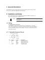
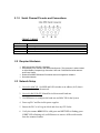
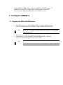
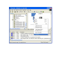
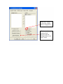
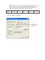
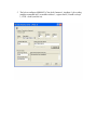
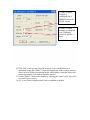
CDN067-3 Quick Start Guide
For use with RSNetworx™
MKS Instruments, Inc.
Control & Information Technology Product Group
1321 Rutherford Lane Suite 200
Austin, TX 78753
Main: 512.719.8000
Fax: 512.719.8096
Manual Rev. 01
Date: October 3, 2005
Copyright
This manual and the software described in it are copyrighted with
all rights reserved. Under the copyright laws, this manual and
software may not be copied, in whole or part, without the prior
written consent of MKS Instruments. The same proprietary and
copyright notices must be affixed to any permitted copies as were
affixed to the original. This exception does not allow copies to be
made for others whether or not sold, but all of the materials
purchased may be sold, given, or loaned to another person. Under
the law, copying includes translating into another language or
format.
© MKS Instruments - CIT Products Group, 2007
1321 Rutherford Lane Suite 2007
Austin, TX 78753
Preface
This document describes how to install and configure the
CDN067-3 Modbus to DeviceNet gateway into and Allan Bradley
PLC system using RSNetworx for DeviceNet.
Table of Contents
1
GENERAL INFORMATION..................................................................................................... 4
2
INSTALLATION AND SETUP ................................................................................................ 4
2.1 WIRING ............................................................................................................................................. 4
2.1.1
DeviceNet Connector Pin out............................................................................................. 4
2.1.2
Serial Channel Pin outs and Connections........................................................................ 5
2.2 REQUIRED HARDWARE .................................................................................................................... 5
2.3 NETWORK SETUP ............................................................................................................................. 5
3
CONFIGURE CDN067-3 ......................................................................................................... 6
3.1
3.2
REGISTER THE EDS WITH RSNETWORX ........................................................................................ 6
CDN067-3 GATEWAY CONFIGURATION .......................................................................................... 7
1 General Information
The CDN067-3 gateway allows the user to easily interface a wide variety of serial
devices to any DeviceNet industrial control network.
2 Installation and Setup
This section describes how to install and connect the CDN067-3 gateway to a
DeviceNet network and to a Modbus device.
Caution
Follow all applicable electrical codes in your area when mounting and wiring any
electrical device.
2.1 Wiring
Communications connections:
The CDN067-3 requires two connections for communications – one to the
DeviceNet network (male 5-pin micro connector) and one to the target Modbus
device (male DB9 connector). The CDN067-3 uses the 24-volt power from the
DeviceNet network.
2.1.1 DeviceNet Connector Pin out
2.1.2 Serial Channel Pin outs and Connections
CDN067-3 (RS485)
DB9 Pin
1
2
3
4-9
Function
RS485 B signal
RS485 A signal
Connect to pin 2 to insert 120 ohm terminating resistor
NC
2.2 Required Hardware
•
•
•
•
MKS Instruments CDN067-3 Gateway.
Allen-Bradley PLC controller with DeviceNet Scanner. This document is written based
on Allen Bradley CompactLogix Controller L32E and 1769-SDN DeviceNet scanner
and Power Supply.
Rockwell Software RSNetworx DeviceNet network configuration software.
DeviceNet Network.
2.3 Network Setup
1. DeviceNet MAC ID: Set MSD and LSD switches to an address (0-63) that is
not currently used on the network.
2. DeviceNet BAUD RATE: Match DeviceNet network baud rate.
3. Use RSNetworx to configure the baud rate and MAC ID for the System.
4. Power up PLC and DeviceNet power supplies.
5. Ensure the PLC is in Program Mode and clear any CPU faults.
6. Verify the scanner MOD LED is solid green and NET LED is flashing green.
If NET LED is flashing red, use RSNetworx to remove all DeviceNet nodes
from the scanners Scanlist.
7. Verify CDN067-3 MOD LED is solid green, NET LED is flashing green. If
NET LED is solid green or flashing red, use RSNetworx to remove all
DeviceNet nodes from the Scanlist, then cycle CDN067-3 power.
3 Configure CDN067-3
3.1 Register the EDS with RSNetworx
1. Once RSNetworx™ is online and the CDN067-3 appears with a question
mark icon, double click on the CDN067-3 icon to launch the EDS wizard
Note
Devices are unrecognized until the EDS file for the device is registered
with RSNetworx™.
2. Select Register an EDS file(s) option and click Next.
3. Select Register a single file option. Browse for the CDN067-3 EDS file.
Click Next when the file path is in the Named: field.
Note
The latest EDS and icon files can be downloaded from www.mksinst.com
4. The next screen shows the RSNetworx installation results. Click Next to
continue.
10. To finish the registration of the EDS file, click Next and then Finish at the
next two screens. Once the EDS wizard closes click the Online operation
from the Network menu. View the DeviceNet network and ensure the
CDN067-3 is labeled CDN067-3 and not Unregistered Device. Click Cancel
when finished.
3.2 CDN067-3 Gateway configuration
The below example uses the modbus network that contains two Watlow MicroDin units
addresses 1 and 2. The example will configure the gateway to set the SetPoint value
Register 300 (0x12C) using the Poll Request and to monitor the Input Actual Register
100 (0x064) and the Input Error Register 101 (0x65) in the Poll Response (please refer
to page 12 of the CDN067-3 user manual revision 1.3, available on the Web, for the same
example.)
1. Remove the CDN067-3 from the scanlist before doing any configuration by
Right-click on the DeviceNet Scanner Module->Properties->Scanlist->Uncheck
“Node Active” box.
Make sure CDN067-3
is not in the scanlist
before configuration.
This button is for
configure Poll
Request, and Poll
Response data size in
Step 7 below
2. Right-click on CDN067-3 device->Class Instances Editor. Some warning
windows popup will appear. Click “Yes” to continue.
3. The MBMAP1-32 is 6 bytes. The data format is provided below (and also on page
4 of the manual). The below example configure MBMAP1 (Class 0x40,
Instance1, Attribute 5) for writing (modbus command 0x06) to modbus address 1,
register 0x12C, NumR is always 1, CTRL =0x40 (write bit set)
Modbus
Address
Command
RegL
RegH
Number of
Bytes
Control Byte
**Note: All values have to be in HEX
Select Get/Set
Single Attribute
here
4. The below configures MBMAP2 (Class 0x40, Instance1, Attribute 7) for reading
(modbus command 0x03) to modbus address 1, register 0x064, NumR is always
1, CTRL =0x80 (read bit set).
5. The below configures MBMAP3 (Class 0x40, Instance1, Attribute 9) for reading
(modbus command 0x03) to modbus address 1, register 0x065, NumR is always
1, CTRL =0x80 (read bit set).
6. The below configures MBMAP4 (Class 0x40, Instance1, Attribute B) for writing
(modbus command 0x06) to modbus address 2, register 0x12C, NumR is always
1, CTRL =0x40 (write bit set).
7. The below configures MBMAP5 (Class 0x40, Instance1, Attribute D) for reading
(modbus command 0x03) to modbus address 2, register 0x064, NumR is always
1, CTRL =0x80 (read bit set).
8. The below configures MBMAP6 (Class 0x40, Instance1, Attribute F) for reading
(modbus command 0x03) to modbus address 2, register 0x065, NumR is always
1, CTRL =0x80 (read bit set).
9. On the DeviceNet Scanner Module, Right-click->Properties->Scanlist->Edit IO
Parameters (refer to second figure in step 1). Since the device was configure with
MBMAP1 and MBMAP4 for Write (n = 2) and MBMAP2, MBMAP3,
MBMAP5, and MBMAP6 for READ (m = 4). IO size will be calculated as
follow:
•
•
Input Size = Number of data bytes the CDN067-3 sends back to the
scanner in a Poll Response = 1 + (m x 2) = 9 bytes (m = # MBMAP
configured for READ: MBMAP2, MBMAP3, MBMAP5, MBMAP6)
Output Size = Data the Application has to send to the CDN067-3 for write
in a Poll Command/Request message = (2 x n) = 4 bytes (n = # MBMAP
configured for WRITE: MBMAP1 and MBMAP4)
CDN067-3 in this
example is
configured with 4
MBMAP entries for
READ: 9 bytes
CDN067-3 in this
example is configured
with 2 MBMAP
entries for WRITE: 4
bytes
10. Click “OK” to accept, and Select the Automap if you want RSNetworx to
automatically map the CDN067-3 input and output bytes to the scanners memory
(Please refer to RSNetworx and appropriate Allen Bradley Controller/DeviceNet
scanner documents if you want to manually map IO)
11. Put the CDN067-3 back on the Scanlist by checking the “Node Active” box (refer
to second figure in step 2).
12. PLC is now ready for application to read or send data to modbus.