1
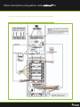
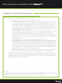
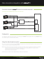
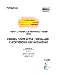
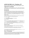
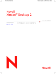
Video doorphone integration with vivimat ® III
Ref: NA-17_v.III
Implicated elements
In the following application note the following elements are discussed:
Ref. vivimat® 3.0
- vivimat® 3.0 controller board and power supply
Ref. vivimat® project
- Software to configure vivimat® III systems
Ref. P-VISION-C7(X)
- 7” Color screen
Ref. MOD-0200
- Video doorphone connection module
Ref. MOD-0350
- GSM module
Ref. MOD-0800
- Audio expansion module.
If you need more specific information on the characteristics of any of them, please refer to the technical data sheets.
Functionality
The vivimat® III systems can provide video doorphone services adding the video doorphone management specific
module, Ref. MOD-0200. This module is connected to the central unit. The vivimat® III systems are compatible with the
AUTA COMUNICACIONES S.L. video doorphone systems. From now on, Auta.
If you want detailed information about the Auta video doorphone systems, consult the technical catalogues.
The vivimat® III systems are compatible with the following Auta systems:
Product range
Compact Digital Dom
(Special version for vivimat systems)
Series
Models
S1, S2, S3, S4 and S5
T, TT and P
Decor Digital
S1, S2, S3, S4 and S5F y FV
(F: talking, FV: talking/video)
Both product ranges have models with a keyboard or buttons.
A vivimat® III system with video doorphone function is composed of the following elements:
Component
vivimat® central unit
Screen
Door Digital
Compact Digital Dom
Description
vivimat® III central unit with
MOD-0001 & MOD-0200
P-VISION-C7(X)
Door Station
Door Station
Reference
vivimat® 3.0
P-VISION-C7(X)
(various models)
(various models) AUTA
Video doorphone integration with vivimat ® III
Embedded box
Video door pone power supply
Boxes to embed the different door
stations (X=1 series 1,
....X=5 series 5)
50902X
Up to 10 housings:
Power supply ATF-98
Up to 40 housings:
Power supply ALV-3.5A
+ Auxiliary power supply ATF-12
715403
715203
Required when using audio
modules
600005
Control module with keypad for
door stations
600006
Required to unite 2 or 3
button-door stations
600002
The SDL allows to communicate
from various common external
accesses with one of the interior
buildings.
730137
Door opener.
Door opener MOD. A
720001
Video distributor
Coaxial video distributor system
DVC-4S (for every 4 housings a
distributor is required)
750498
Digital control module
Keyboard control module
Connection module rows/columns
SDL-line digital selector
715103
The door stations can be with a keyboard or buttons.
Door stations with buttons:
Are the most popular option. Their main advantage is its ease of use by having a call button for each housing. The main
disadvantage of such door stations is that if the number of houses connected is high (over 20), you may require using multiple door stations connected together, and thereby increasing the cost and complexity.
Door stations with keyboard:
Its main advantage is that you can call a large number of homes with just one door station. Its disadvantage is that the
handling is not as intuitive as the button door stations. Another advantage of these door stations is that they allow the
opening of the door by entering a secret PIN.
Video doorphone integration with vivimat ® III
Encoding of the digital system with door station with buttons
Step 1. How does the digital system work:
Each button of the door station has a different call code assigned. When you press the call button, the door station sends
that code to all the vivimat® central units. The central unit that has this code assigned will answer. The code assignment
for each vivimat® central unit is carried out via an 8 position selector located in the MOD-0200 of the central unit. The
central unit is only activated when the MOD-0200 module is encoded and receives its call code from the door station.
Step 2. How to assign call codes:
Locate yourself with the code template next to the door station. Type in the door station, starting with the button marked
with a star, the number of each housing as indicated in the drawing.
Diagram of AUTA. For more information of the diagram, see the specific manual of AUTA
Step 3. Encoding in the vivimat central unit:
Go back into the housing with the code template and encode the central unit accordingly to the button that calls this
housing.
Video doorphone integration with vivimat ® III
Diagram of AUTA. For more information of the diagram, see the specific manual of AUTA
Codes template
Diagram of AUTA. For more information of the diagram, see the specific manual of AUTA
Video doorphone integration with vivimat ® III
Configuring the switches of the central units
Diagram of AUTA. For more information of the diagram, see the specific manual of AUTA
Video doorphone integration with vivimat ® III
Installation
Connection between the vivimat® III central unit, terminals and AUTA control module:
AUTA CONTROL
MODULE
-
Voa
AUTA 24V
07
IN5 IN6 GND IN7 IN8 GND AIN FIN
06
PHONE
_
LINE
Vo
Vo
VI3
VI2
_
VI1
05
VI1
COAXIAL
02
04
IN1 IN2 GND IN3 IN4
03
MEMORY CARD
MAIN BOARD OF VIVIMAT 3.0
TP19
GND
CN10
A2 +V2
GND B1
+V1 +V1 +V1 GND +VA GND +VB
A1 +V2
+V4 +V1
GND B2
GND TT
CN5A
CN5B
EXPANSION BUS
TAMPER
GND SIN SOUT
GND
SIN
SOUT
GND
+V
A
B
GND
IN
+V3 01
CN26
GND
SIN
OUT
08
+
_
CN27B
B1
GND
+V2
A1
Video doorphone integration with vivimat ® III
Connection of the digital door station with buttons with a control module.
Diagram of AUTA. For more information of the diagram, see the specific manual of AUTA
Video doorphone integration with vivimat ® III
Connecting the door stations with the power supply. The door opener and the drip moulding of the building (1
street panel):
Diagram of AUTA. For more information of the diagram, see the specific manual of AUTA
MOD-0200
4 WIRES+COAXIAL
Video doorphone integration with vivimat ® III
Connecting the door stations with the power supply. The door opener and the drip moulding of the building (2
street panels):
Diagram of AUTA. For more information of the diagram, see the specific manual of AUTA
Go to page 11 of the
Application Note
Video doorphone integration with vivimat ® III
Go to page 11 of the
Application Note
Go to page 11 of the
Application Note
Diagram of AUTA. For more information of the diagram, see the specific manual of AUTA
Video doorphone integration with vivimat ® III
Video distribution for screen
Connection of the monitors and vivimat® III central unit of the housing:
MOD
-0200
MOD
-0200
MOD
-0200
MOD
-0200
MOD
-0200
MOD
-0200
MOD
-0200
MOD
-0200
Diagram of AUTA. For more information of the diagram, see the specific manual of AUTA
Video doorphone integration with vivimat ® III
Configuration of Decor Plus digital pannel
Information of AUTA. For more information of the diagram, see the specific manual of AUTA
Configuration Menu (C + Bell + Config. Menu Code (‘1’) + Bell)
- This menu has been created to set the following 7 Panel Parameters:
- OPEN CODE. 4 different common “Open Codes” up to 6 digits, to be assigned to the postman
or to the doorman, but not usually to the neighbours of the building. By default these codes are
101010, 202020, 303030, and 404040. Set any open code to the value 0 implies to disable it.
- OPEN TIME. 2 different configurable “Open Times”. The first one will be used when the user is
outside the building3 and the second one if the user is inside the building (pressing the hall-button
inside the building. This open time is usually longer). By default the Time1=5 seconds and the Time2
= 8 s. (Max Time for both = 9 seconds).
- PANEL NUMBER. There are not dip-switches any more to set the panel number. Now it is configured with the keyboard. By default it will be set to 1. Up to 15 panels could be configured.
- PANEL internal / external. The Panel should be configured as ‘external’ if it performs the call
through an SDL (connected to the X (external) line of the SDL) otherwise the Panel will be configu
red as ‘internal’. From the v2.0, the screen will also show the software version and an internal
identification code.
- SELF STARTING. The self-starting can be enabled or disabled in this menu.
- SWITCHBOARD. This option should be enabled if the installation has a switchboard linked to
the DecorPlus panel. This means that any call code (even a non existing one) will make a call to
the switchboard. If this option is configured as ‘SWITCHBOARD: no’ there it is still the possibility
to assign the call code ‘0’ to a telephone / monitor that will work as if it was a switchboard. The
non existing codes introduced in the panel, will also be redirected to this telephone / monitor.
If the installation needn’t switchboard functions, it is recommended to set ‘SWITCHBOARD: no’
and be sure not having any call code ‘0’ in the data base.4
- NEW ACCESS CODE. It is strongly recommended to change the codes of the Configuration &
Directory menus. Keep in mind that these codes were, by default, ‘1’ and ‘9’ respectively.
• To navigate through the different parameters, we must press the C key, and to change&confirm between
the different options of the same parameter, the Bell key should be pressed. Any numerical parameter can
be changed directly with the numeric keyboard, and if we want to exit this menu, the Bell key must be
pressed when the ‘Exit?’ screen is reached.
NOTES:
3 That is when we call to a flat and someone opens the door, also when we introduce our personal Open Code or a general Open Code.
4 If there is a guard porter button in the installation and it is pressed: If ‘SWITCHBOARD: yes’ it will make a call to the guard porter, if ‘SWITCHBOARD: no’ it will call to the telephone / monitor with the call code 0 only if it exists in the data base.
GENERAL COMMON DOWN-HOLE
4 wires + coaxial
Main monitor
J2 position 1-2 secondary monitor
VIVIMAT
VIDEO
CENTRAL
UNIT
VIVIMAT VIDEO CENTRAL UNIT
Configure both equpments with the same call code
COMPACT DIGITAL MONITOR
Video doorphone integration with vivimat ® III
Diagram of AUTA. For more information of the diagram, see the specific manual of AUTA
Video doorphone integration with vivimat ® III
Connection between vivimat ® III central unit and the terminals
Connecting various P-VISION-C7(X) screens to the central unit:
SCREEN 1
vivimat® 3.0
CONTROLLER BOARD
2
INTERFACE BUS
4
3
AUDIO BUS 1
MOD-0200
SCREEN 2
DVC-45
2
2
4
COAXIAL
3
SCREEN 3
AUDIO BUS 2
2
MOD-0800
4
3
AUDIO BUS 3
Configuration
To configure the video door phone system in the housing with vivimat® Project, please refer to the vivimat® Project
user manual, section 5.7.9.3.2 Video Door Phone.
Using the video doorphone system
The use of the video doorphone through vivimat® III avoids the use of the video doorphone screen, because all the
control is carried out by the P-VISION-C7(X) screen.
Besides the normal use of the video doorphone, open the door, answer a call, turn up/down the volume, etc. it allows:
- Control of the doorphone from the internal telephones of the housing: talk/listen and open the door.
- Call diversion from the video doorphone to the telephone.
- Voice mail of the video doorphone.
Consult the user’s manual of the P-VISION-C7(X) to obtain more information
NA-17_28/10/11-ENG
Product manufactured by: Dinitel 2000 S.A. - Avda. Otaola 20 20600 Eibar ( Guipúzcoa ) Spain
T. +34 902 111 220 / +34 943 820 458 F. +34 902 124 779
www.domotica-vivimat.com
[email protected]