1
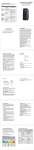
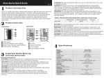
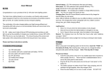
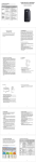
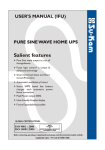
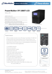
POWERWALKER
Uninterruptible Power Supply
Line Interactive VI 1000/1400/2000
Thank you for purchasing PowerWalker UPS.
User’s Manual
Safety information and operating instructions
are included in this manual. To ensure the
correct use of the UPS, please read this
manual thoroughly before operate it. And
save this manual properly.
28-2PW0000003
1. INTRODUCTION
2. SAFETY REQUIREMENTS
PowerWalker VI series is an intelligent and compact line interactive UPS which is
designed to protect your personal computer or sensitive electronic equipments. The UPS is
Please save this manual properly.
equipped with advanced microprocessor controlled and included built-in boost and buck
information.
AVR to prevent the equipment damage and data loss. The UPS can be automatically started
Comply with all the warnings and operating instructions on the unit and in the
up without AC power supplied. The special feature is that hot-swappable/user replaceable
manual strictly.
battery is easy to replace or change in case of battery. In addition, this UPS provides
To reduce the risk of electric shock, the user must disconnect the UPS from the mains
advanced modem or telephone line surge protection, and the small footprint tower design
supply before installing any cable.
can be placed on your desk space or floor.
To reduce the risk of electric shock.
It is equipped with many features that allow
This manual includes important safety
Please read it carefully and thoroughly before operating the UPS.
Do not attempt to disassemble the UPS.
This
any attached equipment to operate longer and more reliability. PowerWalker VI series
UPS is no user serviceable parts inside. Please contact qualified service personnel
protects computer systems, servers, storage systems, and network peripherals from
to do any service.
blackouts, power surges, and spikes.
Do not connect with laser printers, cosmetic appliances, medical equipments,
microwave ovens, vacuum cleaners or heavy duty hardware to UPS because they
Description of Features:
take too much power.
Compact size and light weight design which can be placed on the cabinet or desk
Do not dispose of batteries in a fire.
They may explore.
Utilized microprocessor control to maximize the reliability and efficiency
Do not open or mutilate batteries.
They contain an electrolyte that is toxic and
Equipped with built-in boost and buck AVR to prevent the equipment damage
harmful to the skin and eyes.
and data loss
Do not allow liquid or foreign object to enter inside of UPS.
Cold start capability enables UPS can be automatically turned on in battery
Do not block off ventilation openings in the UPS system’s housing.
mode during blackout
Do not place the UPS near water or in environments of excessive humidity.
Include discharge, overcharge, and overload protection
Remove personal metal items such as rings, bracelets, necklaces, and watches when
Provides advanced telephone/fax or modem surge suppression protection
working with batteries. Batteries can produce a short-circuit current high enough to
make metal melt, and could cause severe burns.
Built-in RS-232 with connecting intelligent monitoring software
User-replaceable batteries allow on-site battery replacement
USB available(optional)
When replacing batteries, replace with the same number of the sealed lead-acid
batteries.
Back Panel
3. OVERVIEW
Front Panel
1000VA
1.
1400VA/2000VA
Battery Power Supplied Receptacle
The power supplied receptacles are used for battery to power up your equipments
while AC is failure.
1.
ON/OFF Button
2.
The power receptacle is used to plug in the power cord that provides power to the
Press the On/Off button to turn on or off
2.
Fault LED
UPS
3.
- The Fault LED will be on and beeps continuously when the UPS is at faulty condition.
3.
or system overload
4.
connecting the INTERNET service
- Battery Capacity LEDs
On-Line Indicator
5.
- The green light indicator flashes when the internal battery is being used
RS-232 Communication Port
This communication port is used to communicate with a computer or modem and
- The green light indicator illuminates when the input line voltage is normal
Backup Indicator
Telephone/Fax/Modem Surge Suppression Port
This surge suppression port is used to protect the telephone or modem line while
Backup Indicator
4.
Circuit Breaker
The circuit breaker is used to protect your equipment against the event of short-circuit
On-Line Indicator
- Load Level LEDs
AC Input Power Receptacle
support the operating systems
6.
USB Communication Port (optional)
This USB communication port is used by downloaded software
4. INSTALLATION
5.
Connect the Computer
Connect the interface cable from your computer to the output receptacles on the back
Before the installation, please ensure the power switch on the UPS is in “OFF”
position, and the voltage of the AC utility source corresponds to the identification label
panel of the UPS.
6.
Connect the Telephone/Modem Line
Connect a single telephone cable into the “IN” telephone/modem surge suppression
on the rear panel.
port on the back of the UPS. Require another length of telephone cable to connect
1.
Inspection
into “OUT” telephone/modem port on the back of UPS to the modem input socket.
Inspect the UPS upon the receipt.
immediately.
If there is any damage, please report it to dealer
7.
The packaging is used recyclable material, please save it for reuse or
Connect a RS-232 serial cable/USB cable from RS-232/USB communication port on
dispose of it properly.
2.
the back of the UPS to Computer Systems that will be auto detected.
Placement
8.
relative humidity of 0 - 90% without condensing.
free from excessive dust and chemical fumes.
And place the UPS in a location
Please notice that the UPS voltage and
power rating match to the line voltage and load requirements.
Green Mode Function(1000VA only)
“Green mode” enables to save the power if none of the load is connecting.
Install the UPS in a protected area within a temperature range from 0 - 40℃ and
3.
Connect the RS-232/USB*Communication Port
9.
DC Start Function
When the power is not supplied from AC utility, DC start function will be started up
automatically.
Connection
10. Switch Off
Connect the power cord to the utility power to power up the UPS. Press “ON” button
Press “OFF” button to turn off the UPS after use or test.
to turn on the UPS, the green light indicator illuminates that AC utility voltage is
present.
4.
Charge the Battery
Charge the battery automatically when UPS is connected to utility power.
charges may be lost.
Some
It is recommended that the battery will be re-charged for at least
8 hours before using the UPS.
*optional
5. BATTERY REPLACEMENT
6. MONITORING SOFTWARE
Before battery replacement, please ensure the power switch on the UPS is in “OFF”
After the UPS has been installed, you must install the software(Smart Power) that
position.
came packaged with your UPS. Smart Power monitoring software performs the
Step 1: Remove the front panel of the UPS
monitoring and controlling functions. This software displays the status and diagnostic
symptoms on the monitor.
In case of the power failure, it provides the auto shutdown
for the computer.
If you download the software from Internet, please key the serial number:
Step 2: Unscrew and remove the battery bracket
Step 3: Disconnect the battery cable and pull the battery out onto a flat
area
Step 4: Slide the new battery and reconnect the battery cable by
screwing up the battery retaining battery bracket
Step 5:
Close and reinstall the front panel of the UPS
726T25-4791-2N39546.
7. TECHNICAL SPEICIFICATION
MODEL
CAPACITY
INPUT
VA/W
PowerWalker
1000
PowerWalker
1400
PowerWalker
2000
1000VA/600W
1400VA/840W
2000VA/1080W
Voltage
Voltage Range
110/120VAC or 220/230/240VAC
89-145VAC or
170-280VAC
Frequency
OUTPUT
BATTERY
Voltage (Batt.
Mode)
Frequency (Batt.
Mode)
Output
Waveform
(Battery mode)
Battery Type
Backup Time (at
a PC load with
15” monitor)
50Hz or 60Hz +/-1 Hz
40 minutes
3. Battery failure
BUZZER BEEPS
Dimension
DxWxH (mm)
368.3 x 140.2 x 180.4
Smart RS-232
USB Port
(Option)
4. Check the input power and replug
it again
PHYSICAL
INTERFACE
3. Replace with the same type of
8 hours to 90% after complete discharge
Discharge, overcharge, and overload protection
Noise Level
4. Power Connection looses
26 minutes
Full Protection
ENVIRONMENT
hours.
battery or call for service.
PROTECTION
Weight (kgs)
“OFF” or not pressed
12V9Ah x 2
25 minutes
SOLUTION
1. The power switch is in 1. Press power switch to turn on.
weak
Modified Sinewave
12V7Ah x 2
POSSIBLE CAUSE
2. The voltage for battery is 2. Re-charge the UPS at least 8
Fault
Backup Mode
Low Battery
Overload
Fault
AUDIBLE
ALARM
NO LIGHT (UPS
110/120/220/230/240VAC +/-10%
1st green LED lighting
2 to 5 green LEDs lighting indicating load level
1st green LED flahsing
nd
th
2 to 5 green LEDs lighting indicating battery capacity
Red LED lighting
Sounding every 10 seconds
Sounding every second
Sounding every 0.5 second
Continuously sounding
Backup Mode
the problem available.
NOT ON)
Typical : 4-6 ms
AC Mode
To call for service, please have the model, serial number, and description of
PROBLEM
85-140VAC or 162-290VAC
45-65 Hz (Auto Sensing)
Recharge Time
TRANSFER
TIME
INDICATOR
8. TROUBLE SHOOTING
nd
1. Overload of the UPS.
1. Remove the noncritical load or call
for service.
CONTINUOUSLY
th
BACKUP TIME IS
1. Battery failure
1. Replace with same type of battery
or call for service.
SHORT OR ALWAYS
IN “BATTERY
2. AC fuse may be burnout.
MODE”
3. Battery is not fully charged. 3. Re-charge the UPS at least 8
2. Replace fuse or call for service.
hours.
4. Check the input power and replug
13.6
14.2
4. Power Connection loses
it again
16
Less than 45dB
Windows family, Sun Solaris, IBM Aix, Compaq True64,
UnixWare, FreeBSD, HP-UX, Linux and MAC
Windows 98/2000/ME/XP