1
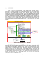
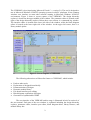
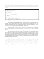
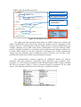
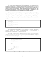
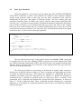
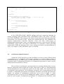
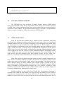
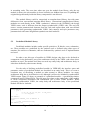
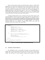
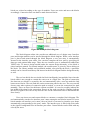
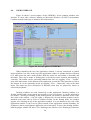
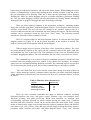
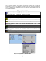
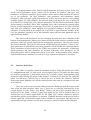
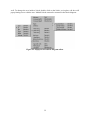
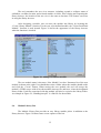
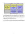
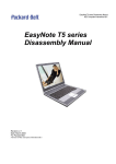
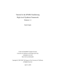
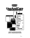
User Manual
Version 1.08
15 January 2000
Universiti Teknologi Malaysia
Faculty of Electrical Engineering
Microelectronics and Computer Engineering (MiCE) Department
Prepared by:
Koay Kah Hoe
Email: [email protected]
Homepage: http://www.geocities.com/kh_koay/
Project Leader:
Assoc. Prof. Dr. Mohamed Khalil Mohd. Hani
Email: [email protected]
Table of Contents
1.0 Overview............................................................................................................................1
2.0 Links to Other Tools ..........................................................................................................3
3.0 Hierarchical Design Exploration........................................................................................5
3.1 Module State ..................................................................................................................6
3.2 Basic Operations ............................................................................................................6
3.3 Various Design Methodology ........................................................................................8
4.0 Parameterized Design Entry...............................................................................................9
4.1 Numeric Parameter ......................................................................................................11
4.2 Data Type Parameter....................................................................................................13
4.3 Architecture Option Parameter ....................................................................................14
4.4 Style Parameter ............................................................................................................15
4.5 Logic Parameter ...........................................................................................................16
4.6 Note Parameter.............................................................................................................16
4.7 Link Parameter.............................................................................................................17
4.8 Generic Parameter........................................................................................................17
5.0 Dynamic Module Library.................................................................................................18
5.1 VHDL Module Library ................................................................................................18
5.2 Predefined Module Library..........................................................................................19
6.0 Interface Port Editing.......................................................................................................20
7.0 Block Diagram Exploration .............................................................................................21
8.0 Generation of Synthesizable VHDL ................................................................................23
9.0 User Interface...................................................................................................................24
9.1 Design Hierarchy Explorer ..........................................................................................26
9.2 Parameter Editor ..........................................................................................................28
9.3 Interface Port Editor.....................................................................................................30
9.4 Block Diagram Editor ..................................................................................................31
9.5 Library Browser ...........................................................................................................34
9.6 Module Library Bar .....................................................................................................35
1.0
OVERVIEW
Figure 1 shows a conceptual diagram of the VHDL Module Generator, which is
abbreviated as VHDLMG from this point onwards. In general, the term ‘tool’ in this manual
also refers to the VHDL Module Generator, unless otherwise stated. The main project
window in the VHDLMG is the design hierarchy explorer. As VHDL design entry lacks the
convenience for users to explore design hierarchy, the tree view design hierarchy explorer is
provided to facilitate hierarchical and modular design methodology. Users can create topdown, bottom-up or mixed design conveniently using the design hierarchy explorer. Each
object in the tree view is a design module, which is always associated with a VHDL file.
Each design module is associated with a parameter list, a port interface list, and a block
diagram.
VHDL Module generator
Parameter Editor
Design Hierarchy Explorer
Interface Editor
Synthesizable
VHDL
Block Diagram Editor
User VHDL
entry
Module
Library
Figure 1: Conceptual diagram of VHDLMG
The VHDLMG allows parameterized VHDL entry where users can insert and modify
data widths, data types as well as architectural options easily without changing the VHDL
code manually, but through the parameter editor window. The parameterization feature
enables creation of dynamic module library, where users can create user-defined library
modules for future reuse. The interface editor window enables insertion, modification, and
viewing of port interface of VHDL entities. This feature eliminates VHDL text coding of port
list. Block diagram editor window provides a more intuitive and realistic pictorial view of
designs. The output of the tool is synthesizable VHDL code. The tool will generate the
VHDL source codes in synthesizable form.
1
The VHDLMG is developed using Microsoft Visual C++ version 5.0. The tool is designed to
run in Microsoft Windows 95/98/NT operating systems in x86 PC platforms. It has common
windows user interface as most other software running in Microsoft Windows 95/98/NT
environment. Figure 2 shows a screen capture of the VHDLMG. The design hierarchy
explorer is located at the upper middle of the window. The parameter editor is located on the
right of the design hierarchy explorer. Below these two sections is a command log window.
The interface editor is located at the lower left side of the window, while the block diagram
editor is located at the lower right side of the window. At the upper left corner, there is a
library module picker.
Figure 2: Screen Capture of VHDLMG
The following subsections will describe features of VHDLMG, which include:
•
•
•
•
•
•
•
Links to other tools
Exploration of designs hierarchically
Parameterization of designs
Dynamic module library
List-based interface port editing
Block diagram exploration of designs
Generation of synthesizable VHDL
The user interface of the VHDLMG and its usage is illustrated in brief in section 9 of
the user manual. Each part of the user window is explained including the design hierarchy
explorer, parameter editor, interface port editor, block diagram editor, library browser, and
module library bar.
2
2.0
LINKS TO OTHER TOOLS
VHDLMG is not a stand-alone design tool. It is a design entry tool that generates
synthesizable VHDL. It must be used in conjunction with other downstream tools for
verification and implementation. It can launch other downstream tools, such as those which
are commonly used in a normal design flow. These tools include:
1. VHDL Simulation – After a design is created using VHDLMG, the resulting VHDL
output can be simulated using a VHDL simulation tool, e.g. Aldec Active-VHDL.
2. Synthesis – The output VHDL from the VHDLMG is then passed through the synthesis
process, converting it to hardware netlist code.
3. Functional Simulation – The netlist obtained from the synthesis tool may be verified
using functional simulation tools.
4. Implementation – The netlist obtained from the synthesis tool is converted to a physical
layout of targeted implementation technology.
5. Timing Simulation – The physical layout obtained from implementation process can be
simulated to verify the design, but this time, with timing information.
Users can invoke the above tools from the Tool menu. In addition, users can open a
design flow window, which shows graphically the design flow in sequence, as shown in
Figure 3. Users can launch a tool by clicking left mouse button on icon for the particular tool.
VHDLMG does not hardcode which particular tool to use for each link in the design
flow window. Instead, these are set in tools setting window by invoking “Tools – Setting…”
menu. Figure 4 shows this window. Path name column at the left specifies program to launch,
while Parameters column at the right is for optional arguments or parameters needed when
launching a particular application.
3
Figure 3: Design flow window
Figure 4: Tools setting window
In a design project, users can further select project file names to load when launching
downstream tools. These can be set at the root parameter list of the design project. Figure 5
shows an example parameter list. Special parameters including Synthesis, Implementation,
VHDL_simulation, Functional_simulation, and Timing_simulation are used by the tool to
identify project file names to load for the tools. These settings are optional; users can left the
columns blank. Settings here are local for each design project, whereas the settings for tools
are common for any design projects.
4
Figure 5: Parameter List at Root
3.0
HIERARCHICAL DESIGN EXPLORATION
Visualization of the design hierarchy is implicitly provided in schematic-based
design. In contrast, VHDL-based design entry lacks a convenient way for designers to
visualize the system hierarchy, as all descriptions are written in text. Some synthesis tools can
create a hierarchical view of design entities after synthesizing a design. This is performed
only after designers have completed their designs; even that, only when the design is
synthesized successfully. The VHDL source files are then inserted in flat manner. Clearly, it
does not aid the design process.
The VHDLMG overcomes the stated weakness. In the tool, the VHDL source files are
organized and displayed in the actual design hierarchy through a window called design
hierarchy explorer. Users can view and manipulate the design hierarchy right from the
beginning of the design process using the design hierarchy explorer.
Figure 6 shows an example view of the design hierarchy explorer. The first icon on
the top of the view shows the subfolder name (Test Project) where all the source files reside.
It is created automatically when a new project is created and is non-removable. Users can
rename the subfolder name as required.
Figure 6: Example design hierarchy tree
Except for the first icon, each icon in the tree represents a design module, which is
associated with a VHDL source file. The VHDL filename always has the same name with the
module name shown at the design hierarchy explorer. Different icon symbols are used to
differentiate different types of modules. The module with the name ThisPackage in the
example is a VHDL package definition module. TopLevel, Controller and DataPath in the
example are normal VHDL design modules with entity and architecture bodies. Only one
entity body is allowed inside each module of this type. Counter and Pipelined_Multiplier are
5
library modules. A library module can have more than one entity body. The module name is
the top-level entity name of the library module. Internal entities of library modules are hidden
from users. RAM16X1 and BUFGP are predefined modules. Predefined module can be either
a primitive component predefined in the synthesis tool or an external component that is
defined using other representation, like schematic or netlist.
Among available functions of the design hierarchy explorer includes add new module,
insert library or predefined module, cut, copy, paste, move, rename, and remove. By using
these functions, top-down, bottom-up or mixed design methodologies can be created
conveniently. All these functions are provided in the graphical user interface of the design
hierarchy explorer. These functions make design work much easier to manage.
3.1
Module State
Each module in the design hierarchy view is associated with a state symbol to the left
of the module icon to indicate the current state of the module. The VHDLMG updates the
states after certain operations that could change the state has been taken or after the tool gains
control back from other program. The defined states are listed in Table 1.
Table 1: Module states
The module is new and unnamed yet.
The module’s VHDL file has been modified
The module has been analyzed and no problem is encountered
Error(s) found in the module’s VHDL file
The module’s VHDL file cannot be found or accessed
When a module’s VHDL file is modified or its parameter list is altered, the state
symbol will change to a question mark stating that the object should be analyzed again. All
the states of its upper modules will change to question mark, too, as changing a child module
will affect all its parent modules.
3.2
Basic Operations
To insert a new module into a design project, the user should select the insertion point
where the new module will be created under the selected module as child module. After
creating the new module, the user is required to enter a name for the module. The module
name will be the entity name of the VHDL code of this module. A template VHDL file with
an entity body and an architecture body will be created automatically. Figure 7 shows the
template VHDL code created by the tool. User must not alter the entity name in the VHDL
6
file. If the new module is created under another module, component declaration and example
component instantiation for this module will be inserted automatically at the upper hierarchy
module.
-- mymodule
library IEEE;
use IEEE.std_logic_1164.all;
use IEEE.std_logic_arith.all;
entity mymodule is
port (
-- Enter port list here
CLK : in STD_LOGIC
);
end mymodule;
architecture mymodule_arch of mymodule is
begin
-- Enter concurrent statements here
end mymodule_arch;
Figure 7: A template VHDL code created when a new module is inserted
The tool allows renaming module name. The tool will check for existence of the new
assigned name, if found, the tool will prompt the user to enter another name. The tool
automatically changes entity name, component declaration, component instantiation, and all
occurrences of the old name to the new name in the VHDL code.
Moving a module within the same hierarchy can be performed by using move
functions. This operation is just to order modules as the user prefers, it doesn’t affect the
design.
When performing module removal, the tool will prompt for confirmation to avoid
accidental removal. When removing a module, its VHDL file is actually renamed to backup
file (*.bak). If the module has child modules beneath it, all the child modules will be removed
as well. Upper-hierarchy modules of the removed module will be set to unanalyzed state.
After analyzing, the removed module’s component declaration at upper hierarchy module is
automatically removed by the tool.
Clipboard functions are available for users to move, copy, or duplicate design
modules from one place to another. Cut operation does not immediately remove modules, but
just marking the selected module and its child modules as cut status. Then, when user point to
another place outside the marked modules and invoke paste operation, the cut modules will
be pasted to the new location. If user does not perform paste operation, the cut modules will
not be removed. Figure 8 shows an example of cut operation where DataPath module is cut
and then paste some where else.
7
Figure 8: Cut and paste operation at design hierarchy explorer
Copy operation marks the selected module and its child modules as copy status. Then,
when user point to another place outside the marked modules and invoke paste operation, the
copied modules will be duplicated at the new location. Figure 9 shows an example of copy
operation where DataPath module is copied and then paste somewhere else.
Figure 9: Copy and paste operation at design hierarchy explorer
Same module name for two modules within a design project is not allowed. If this
situation is encountered during copy and paste operation, as the shown example, the tool will
change the module names of the duplicated modules. Notice that the name for predefined
module RAM16X1 is not changed, this is because predefined modules must have fixed
names.
Clipboard functions at the design hierarchy explorer are supported within the same
application window only. Cut or copied modules are invalid in the clipboard after the design
project is closed. Thus, moving or copying modules from one design project to another can
be performed only if both projects are opened in the same application window.
3.3
Various Design Methodology
By using the basic functions provided, various design methodologies can be practiced
in this design environment, including top-down design, bottom-up design or mixed design.
8
To create top-down design, the topmost design module is inserted under the root icon
of the design hierarchy explorer. Then, sub-modules under the top module can be inserted.
Interface ports of the sub-modules can be defined using the interface port editor without
opening VHDL file. The sub-modules are like black boxes with external interfaces defined,
but internal functionality is still undefined. Component declarations and example component
instantiations of the sub-modules are inserted by the tool at the top module. Interconnection
among the sub-modules can then be created by editing the top module’s VHDL file. After
this, the top-level design is completed. Designer can then move down to define each submodule in detail. The similar process is carried out until all sub-modules are defined
completely.
To create bottom-up design, the bottommost modules are inserted under the root icon
of the design hierarchy explorer. Each module will be described completely before moving
up to the next level. Several small modules will then be combined to make a bigger module.
This is done by first inserting a new module under the root icon. Then, the designed submodules should be cut and pasted under the new module. The tool will automatically insert
component declarations and example component instantiations at the new module. After this,
designer can define the interconnections among the sub-modules. Similar process is carried
out from bottom-up until reaching the top-level design.
In a design process, it is seldom using only one methodology throughout the design. A
more usual way of a design process will be combining both design methodologies. A topdown design is used until a certain point, then bottom-up designs are used to design the submodules, or simply reuse previous design modules in the library. The tool can handle the
various design methodologies seamlessly.
4.0
PARAMETERIZED DESIGN ENTRY
Parameterized design entry is one of the main features of VHDLMG. Modules or
components can be described in a generalized form and made specific by using generic
parameters. Take the case of a simple example, a counter. A generalized counter can be made
and specified with parameters like the counter’s width, its initial value, stop value, increment
step, and architecture options, such as binary or one-hot encoding.
By using generic clauses, configuration statements, enumeration, etc., generalized
components can be described in VHDL code. Furthermore, multiple levels of parameter
passing can be done as well. The VHDLMG takes advantage of these features and further
enhances them to windows user interface. The tool searches through the VHDL code for all
parameterizable elements and extracts them to a parameter editor, where users can view and
edit the parameters in the tool without opening the VHDL file. Thus, it makes design work
easier and faster for hardware designers. Figure 10 shows an example of parameter extraction
process. On the other way round, users can insert new parameters to a module through the
VHDLMG’s user interface. Then, the tool will generate the corresponding VHDL code
automatically.
9
VHDL entity & architecture body
entity Adder is
generic(
DataWidth: INTEGER := 8);
port(
A,B: in AdderType(DataWidth-1 downto 0);
SUM: out AdderType(DataWidth downto 0)
);
end Adder;
architecture SpeedOptimized of Adder is
begin
-- Speed optimized adder architecture here
end SpeedOptimized;
Numeric parameter
Data type parameter
Architecture option
parameter
Parameter List
architecture AreaOptimized of Adder is
begin
-- Area optimized adder architecture here
end AreaOptimized;
Figure 10: Parameter extraction
One might argue that parameterization makes the VHDL coding more complex and
harder to understand. It also takes longer during the synthesis process comparing to fixed
designs. However, considering that a design usually involves repeated modifications (for
example, changing a bus width could involve modifications in several different VHDL
entities), designers would have to restudy the codes to find where the changes would have to
be made, which would be even more ineffective. If designers have created parameterized
designs from the beginning, future modification work is relatively easy. In other words,
parameterized design entry enables rapid prototyping of designs.
The parameterizable elements supported by VHDLMG include the numeric
parameter, data type parameter, architecture option parameter, style parameter, logic
parameter, etc. Users can insert parameters either through manual VHDL coding or through
the tool’s user interface. Figure 11 shows a practical example of parameter list for a data
register. The following subsections discuss each type of parameter in detail.
Figure 11: Parameter list for a data register
10
4.1
Numeric Parameter
Numeric parameter describes data width, number range, or any other integer numeric
values used in VHDL code. Numeric parameters are declared in generic clause at entity
header of a module as shown in Figure 12. The module is DataRegister which has parameter
list shown in Figure 11. The generic clause is located immediately after the keyword “is”.
Only integer numbers are supported. The numeric parameter is identified by the keyword
“integer” in the generic list. Users can modify the numeric parameter DataWidth in the
parameter editor. Corresponding changes will be made by the tool in the VHDL code
automatically.
entity DataRegister is
generic (
Author: note := "Koay Kah Hoe";
Description: note := "A set of flip-flops";
Documentation: file := "DataRegister.pdf";
DataType: type := SIGNED;
DataWidth: integer := 8;
CLK_EDGE: STD_LOGIC := '1';
RST_ACTIVE: STD_LOGIC := '1'
);
port (
D: in DataType(DataWidth-1 downto 0);
Q: out DataType(DataWidth-1 downto 0);
LOAD,RESET,CLK: in STD_LOGIC
);
type ENUM_ChipEnable is (HIGH, LOW, DontUse);
constant ChipEnable: ENUM_ChipEnable := DontUse;
end DataRegister;
Figure 12: Entity body of DataRegister
If this module is used under another module at upper design hierarchy, the userdefined parameters will be inserted in the component declaration at the architecture
declarative part of the upper-hierarchy module, as shown in Figure 13.
architecture upper_arch of upper is
-- VHDL Module Generator component declarations
component DataRegister
generic (
Author: note := "Koay Kah Hoe";
Description: note := "A set of flip-flops";
Documentation: file := "DataRegister.pdf";
DataType: type := SIGNED;
DataWidth: integer := 8;
CLK_EDGE: STD_LOGIC := '1';
RST_ACTIVE: STD_LOGIC := '1'
);
port (
D: in DataType(DataWidth-1 downto 0);
Q: out DataType(DataWidth-1 downto 0);
LOAD,RESET,CLK: in STD_LOGIC
);
end component;
for Conf_DataRegister: DataRegister
use entity WORK.DataRegister(Asynchronous_Reset);
begin
-- VHDL Module Generator component instantiations
U_DataRegister: DataRegister
port map (D, Q, LOAD, RESET, CLK);
...
...
end upper_arch;
Figure 13: Component declaration at upper-hierarchy module
11
To use the numeric parameter in VHDL coding, there are a number of ways,
depending on the function of a particular numeric parameter. In general, it can be used to
substitute any fixed numbers used in VHDL coding. It can be used to specify the range of
signals in interface port declarations, internal signal declarations, expressions, etc. Like
the example shown in Figure 12, it is used to specify the range of signal D and Q. The
parameter can be used in conjunction with arithmetic or relational operators.
Numeric parameter can be used in generate statements as well, as shown in Figure
14, assume that NumParam is a numeric parameter. This is useful when the number of
sub-modules to be created is depended on the numeric parameter, as usage in the first
case of the example. In other situation, different circuitry should be applied with different
value of numeric parameter, as usage in the second and third generate statements in the
example.
U1: for I in 0 to NumParam-1 generate
...
end generate;
U2: if NumParam>1 generate
...
end generate;
U3: if NumParam<=1 generate
...
end generate;
Figure 14: Using numeric parameters in generate statements
For sequential statements within a process, function or procedure, the numeric
parameter could be used in many ways, including using it in loop statements, if
statements, and case statements. As shown in Figure 15.
The VHDL synthesizer in use, the FPGA Express, supports the generic mapping
of numeric parameter. Thus, when the tool generates synthesizable VHDL, the coding for
the numeric parameter is unchanged.
process
begin
for I in 0 to NumParam-1 loop
...
end loop;
if NumParam>1 then
...
else
...
end if;
case NumParam is
when 1 => ...
when 2 => ...
when others => ...
end case;
end process;
Figure 15: Using numeric parameters in process
12
4.2
Data Type Parameter
Data type parameter can be used to specify signal types like SIGNED, UNSIGNED,
STD_LOGIC_VECTOR, or others. This parameter is needed as there might be different
designs using different kinds of data type, but the basic components used could be
independent of data type and usable in different designs. The tool extracts data type
parameter from three places in VHDL code: generic clause at entity header identified by the
keyword “type”, port clause at entity header, and signal declaration at architecture declarative
part, as shown in Figure 16. For parameterized data type Type2 and Type3 in the example
below, the tool checks whether they are common standard data types, if not, the tool will
extract them as data type parameter. For Type4, the type is already declared before the signal
declaration, thus, it is not treated as data type parameter.
entity Adder is
generic(
Type1: type := SIGNED
);
port(
A, B: in Type2(7 downto 0);
SUM: out Type2(7 downto 0)
);
end Adder;
architecture Adder_arch of Adder is
signal C: Type3(7 downto 0);
type Type4 is array (0 to 7) of SIGNED(7 downto 0);
signal D: Type4; -- Type4 is not data type parameter
begin
:
:
Figure 16: Places to extract data type parameter
The use of the keyword “type” in the generic clause is not standard VHDL syntax and
is recognized by this tool only. Standard VHDL syntax does not allow parameterized data
type. When generating synthesizable VHDL, the tool will remove the parameterized data type
from the generic list and replace all occurrences of the parameterized data type with userdefined one in the parameter list.
The data type parameter is used mostly at declaration of signals, either external or
internal ones, as has been shown in Figure 16. There is a special case when different circuitry
is needed for different data types. This happens for SIGNED or UNSIGNED data types.
Arithmetic operations on the two data types can be different. To handle this situation, an
enumeration type is defined for possible choices of data types. Then, a constant of the
enumerated type is declared and assigned the selected data type parameter, as shown in
Figure 17. In the architecture body, either conditional generate statements for concurrent
statements or if statements for sequential statements can be used to write different coding for
different data types.
13
entity mymodule is
generic (
Type1: type:= SIGNED;
...
);
port (
...
);
end mymodule;
architecture mymodule_arch of mymodule is
type ENUM_cType1 is (SIGNED, UNSIGNED); -- Choices of data type
constant cType1: ENUM_cType1 := Type1;
...
begin
U1: if cType1=SIGNED generate
-- Code for SIGNED data
...
end generate;
U2: if cType1=UNSIGNED generate
-- Code for UNSIGNED data
...
end generate;
...
end mymodule_arch;
Figure 17: Illustration of coding different circuitry for different data types
In the “IEEE.STD_LOGIC_ARITH” package, data type conversion functions are
defined, including CONV_SIGNED, CONV_UNSIGNED, CONV_STD_LOGIC_VECTOR,
and CONV_INTEGER. These functions are used to convert data types from one to the other
conveniently. The word after CONV_ denotes the resultant data type. The VHDLMG also
supports parameterized conversion functions. Users can write CONV_Type1 as
parameterized function name. Type1 is a parameterized data type, which can take SIGNED,
UNSIGNED, STD_LOGIC_VECTOR or INTEGER as its parameter. When generating
synthesizable VHDL, the function CONV_Type1 will be converted to selected parameter of
Type1, for example, CONV_SIGNED if Type1 is SIGNED.
4.3
Architecture Option Parameter
Architecture option parameter provides flexibility for users to choose different kinds
of architectures of a component. This permits designers to evaluate different kinds of
architectures quickly. In VHDL syntax, an entity body could have several architecture bodies
associated with it. Configuration declaration or configuration specification is used to specify
which particular architecture to choose.
The tool looks for architecture option parameter by searching whether there are more
than one architecture bodies defined for an entity. Refer back to Figure 10, SpeedOptimized
and AreaOptimized are two architecture options for the entity Adder. They will be extracted
as architecture option parameter. The architecture selected by users in the parameter list will
be stated as configuration specification at architecture declarative part in the upper-hierarchy
module. An example of configuration specification can be seen in Figure 13, where
Asynchronous_Reset is chosen for the DataRegister module. However, VHDL synthesizer
used does not recognize configuration specification. To compensate this limitation, when
14
generating synthesizable VHDL, only selected architecture option is added to the output
VHDL file. Other architecture options are discarded.
4.4
Style Parameter
Style parameter is very similar to architecture option parameter. For architecture
option parameter, user can select one architecture from several architecture bodies. However,
it poses a limitation that only one architecture option parameter is allowed in one module.
This is not practical enough, as parameterized designs often need several independent
architecture options. The style parameter solves this limitation.
The DataRegister module is used as an example to illustrate the use of style
parameter. Figure 11 shows the parameter list of the module. The architecture option
parameter is used to select the style of reset signal. The style parameter is used to select the
style of chip enable signal. These two parameters are independent to each other. The obvious
advantage of style parameter is that the number of this parameter is unlimited in a module,
allowing multiple independent style options to choose.
Different from other parameter types, the style parameter is declared at entity
declarative part after port clause in an entity body, as shown in Figure 18. An enumeration
type is used to define available style options. This is followed by a constant declaration of the
enumeration type. The constant name is the style parameter name. The assigned constant
value must be one of the enumerated choices. It denotes the selected style parameter.
entity DataRegister is
generic (
...
);
port (
...
);
type ENUM_ChipEnable is (HIGH, LOW, DontUse);
constant ChipEnable: ENUM_ChipEnable := DontUse;
end DataRegister;
Figure 18: Style parameter declaration
The style parameter can be used in two ways. For concurrent statements, conditional
generate statements is used, as shown in Figure 19. For sequential statements, if statements is
used, as shown in Figure 20.
U1: if ChipEnable=DontUse generate
...
end generate;
U2: if ChipEnable=HIGH generate
...
end generate;
Figure 19: Using style parameter in concurrent statements
15
if ChipEnable=DontUse then
...
end if;
if ChipEnable=HIGH then
...
end if;
Figure 20: Using style parameter in sequential statements
When generating synthesizable VHDL, the VHDL coding for style parameter is
unchanged, since the syntax is fully supported by the synthesizer used.
4.5
Logic Parameter
Logic parameter has two possible values only, either ‘0’ or ‘1’. This kind of parameter
is useful in specifying active logic level or triggering edge of control signals, like active clock
edge, reset active level, enable active level, etc. Logic parameter is declared at generic clause
identified by the keyword “STD_LOGIC”. The declaration can be seen in DataRegister
example in Figure 12. Example usage of the logic parameter is shown in Figure 21. An
asynchronous flip-flop is coded with parameterized reset active level (RST_ACTIVE) and
clock edge (CLK_EDGE).
process (CLK,RESET)
begin
if RESET = RST_ACTIVE then
Q <= (others => '0');
elsif CLK'event and CLK=CLK_EDGE then
Q <= D;
end if;
end process;
Figure 21: Using logic parameter
The generic clause with STD_LOGIC keyword is not standard VHDL syntax. When
generating synthesizable VHDL, the tool replaces the logic parameter with the selected logic
(‘0’ or ‘1’) directly into the VHDL code, and removes its declaration at generic clause.
4.6
Note Parameter
Note parameter is used to write a one line comment or note in the parameter list. The
parameter does not affect design at all. Note parameter is declared in generic clause using the
keyword “note”. An example declaration is shown in Figure 22. The parameter is enclosed
with double quotes. When generating synthesizable VHDL, the note parameter at generic
clause is removed.
16
generic (
Author: note := "Koay Kah Hoe";
Description: note := "A set of flip-flops";
...
);
Figure 22: Declaration of note parameter
4.7
Link Parameter
Link parameter is used to provide linkage to other files that are associated with the
design. It could be any registered file type. Link parameter is declared in generic clause,
which is identified by the keyword “file”. The parameter is enclosed with double quotes.
Example declaration is shown in Figure 23. When users double click on this parameter at the
parameter list window, the tool will invoke default viewer or application for the file type.
This parameter is useful in associating documentation file to a design. It could also be used to
invoke other design files. For instance, a design could be entered in finite state machine. By
providing the link to the FSM design file, user can easily open the FSM design file for editing
or viewing. When generating synthesizable VHDL, the link parameter is removed from the
generic clause.
generic (
Documentation: file := "DataRegister.pdf";
...
);
Figure 23: Declaration of link parameter
The link parameter can also be used as hyper link to internet addresses and email
addresses. To set a link to an HTTP site, the parameter should be started with “http://”. To set
a link to an FTP site, the parameter should be started with “ftp://”. Activating the hyper link
of these types will invoke default internet browser to the specified site. To set an email link,
the parameter should be started with “mailto:”. Activating the email link will invoke default
email program’s mail composer addressed to the specified email address.
4.8
Generic Parameter
Generic parameter is used at LPM modules for Altera predefined modules only,
which is served for compatibility with parameter entries of LPM modules. Generic parameter
is declared in generic clause using the keyword “string”. An example declaration is shown in
Figure 24. The parameter is enclosed with double quotes. For LPM modules, parameters
other than numeric parameter are specified using the “string” keyword in generic clause.
17
generic (
...
LPM_TYPE: string := "LPM_CLSHIFT";
LPM_SHIFTTYPE: string := "LOGICAL";
LPM_HINT: string := "UNUSED"
);
Figure 24: Declaration of generic parameter
5.0
DYNAMIC MODULE LIBRARY
The VHDLMG uses two categories of module libraries, namely VHDL module
library and predefined module library. The VHDL module library stores modules described
in VHDL codes, while predefined module library stores modules that have been predefined or
described in other mediums. The predefined module library is provided as a supplementary
feature in support of using non-VHDL sub-modules in VHDL designs.
5.1
VHDL Module Library
From the fact that most systems share a number of basic components, apart from
providing a basic design environment, many EDA tools often come with a set of predefined
component libraries. This is very useful for designers to avoid designing from scratch. There
are several forms of component libraries used in EDA tools, i.e. fixed, template, or wizard
form. Fixed library components have the least flexibility among these three methods, as users
need to modify the codes to suit the design. Template-based components provide generic
VHDL codes. Users can easily modify components by changing available parameters. It has
slower synthesis run time and is prone to create redundant hardware. Wizard-based library
creates VHDL codes after users have specified the parameters. The resulted VHDL code is
clean, because specified parameters have been inserted directly into the VHDL code.
However, created code is fixed. If modification is needed, users have to rerun the wizard.
Many EDA tools do not support dynamic library creation of reusable components, but
only a fixed set of library modules is provided. In practical cases, hardware designers often
need to reuse their previous designs in other places or for upgrading. If the design entry tool
allows dynamic storage of library modules, future designs could be speeded up by just
retrieving previously designed modules from library. In the VHDLMG, dynamic module
library is enabled by using parameterized design entry, as it provides a method to create
generalized modules that could be stored as library modules. Thus, any reusable designs can
be stored in module library dynamically for future reuse.
Modules in library are just a collection of VHDL files. All parameter information is
recorded in the VHDL file itself. When a user stores a design into library, the tool will store
all parameters currently defined in the library VHDL file. If a design consists of several submodules in several files, when it is stored in library, the tool will combine them into one file
18
in ascending order. The next time when user gets the module from library, only the top
module is shown, the sub-modules in lower hierarchy are hidden from users. Expanding the
original design hierarchy inside the library components is not allowed.
The module library could be categorized as template-based library, but with some
differences from conventional template-based library. Conventional template-based library
modules are used directly in the VHDL synthesizer, whereas in the VHDLMG, the design
VHDL source code is different from the output (synthesizable) VHDL code. The tool will
remove certain parameterized elements from the code and replace them with user-defined
parameters when generating synthesizable VHDL. Only numeric and style parameters stay
parameterized with some insignificant synthesis run time tradeoffs.
5.2
Predefined Module Library
Predefined modules include vendor specific primitives, IP blocks, cores, schematics,
etc. These modules are predefined by the synthesis tool or defined using other types of
notation, like netlist or schematics, that are understood by synthesis tool or implementation
tool used.
In order to use this type of modules in VHDL designs, they have to be declared as
components in the declarative part of the architecture body in the VHDL code where these
modules are used. The module itself does not need any entity body and architecture body, as
it has been defined by other means already.
For the sake of defining predefined module in VHDLMG, the interface ports and
parameter entries of predefined module are described in an entity body. This is to create a
consistent way of describing a module as other normal or library modules. An empty
architecture body has to be defined as well, although it will not be included in synthesizable
VHDL output. Figure 25 shows an example of a predefined module – a predefined primitive
component used in Xilinx FPGA. The tool uses port clause at the entity body of the module
to create component declaration and instantiation just as other VHDL modules. When
generating synthesizable VHDL, the entity body and architecture body of the predefined
module will not be included.
-- Xilinx Component: RAM32X1
entity RAM32X1 is
port (
D, A0, A1, A2, A3, A4, WE : in STD_LOGIC;
O : out STD_LOGIC
);
end RAM32X1;
architecture RAM32X1_arch of RAM32X1 is
begin
-- Null architecture body
end RAM32X1_arch;
Figure 25: RAM32X1, an example of predefined module
19
Figure 26 shows another example of predefined module, which is an LPM module
supported by Altera MAX+plus II implementation tool. Besides defining the interface ports,
LPM module also requires a list of parameters, which are described in the generic clause.
Two types of parameters are used, where parameter with “integer” keyword is used for
numerical parameter and “string” keyword is used for any other types of parameter. For
example, the parameter LPM_INDATA in Figure 26 can be set as UNREGISTERED or
REGISTERED, while the parameter LPM_FILE is used to point to a file defining initial
values of the RAM. Documentation of the LPM modules must be referred, which is available
in Altera MAX+plus II, to ensure proper usage of these modules.
Changing predefined module’s name is disallowed. The name and the interface of the
predefined modules are fixed since they have been generated. Otherwise, the synthesis tool or
implementation tool cannot recognize the modules. Optionally, the architecture body of
predefined module can contain behavioral VHDL model of the predefined module. Certain IP
blocks or cores provide the behavioral VHDL model for simulation purposes. By having the
behavioral model, the tool can generate code for VHDL simulation. To do this, the
predefined module has to be switched to normal VHDL module, where entity and
architecture bodies will be included in the output VHDL.
-- LPM_RAM_DQ
entity LPM_RAM_DQ is
generic (
LPM_WIDTH: integer := 8;
LPM_TYPE: string := "LPM_RAM_DQ";
LPM_WIDTHAD: integer := 4;
LPM_NUMWORDS: string := "UNUSED";
LPM_FILE: string := "UNUSED";
LPM_INDATA: string := "UNREGISTERED";
LPM_ADDRESS_CONTROL: string := "REGISTERED";
LPM_OUTDATA: string := "UNREGISTERED";
LPM_HINT: string := "UNUSED"
);
port (
DATA: in STD_LOGIC_VECTOR(LPM_WIDTH-1 downto 0);
ADDRESS: in STD_LOGIC_VECTOR(LPM_WIDTHAD-1 downto 0);
WE: in STD_LOGIC;
INCLOCK: in STD_LOGIC;
OUTCLOCK: in STD_LOGIC;
Q: out STD_LOGIC_VECTOR(LPM_WIDTH-1 downto 0)
);
end LPM_RAM_DQ;
architecture LPM_RAM_DQ_arch of LPM_RAM_DQ is
begin
-- Enter concurrent statements here
end LPM_RAM_DQ_arch;
Figure 26: LPM_RAM_DQ, an LPM predefined module
6.0
INTERFACE PORT EDITING
The VHDLMG provides a user-friendly environment to create interface ports of
modules. Figure 27 shows an example of the interface port editor. The editor is divided into 4
columns. The “Name” column specifies the port name of a signal. User can edit in this
column. The tool checks for correct naming of signal names according to the VHDL
20
identifier naming standard. In Figure 27, the “_RESET” signal name is invalid identifier
name. Thus, the tool displays a red knob at the first column to denote erroneous syntax.
Figure 27: Interface port editor
The “Mode” column denotes signal’s port mode, there are five kinds of modes: in,
out, inout, buffer, and linkage. The VHDLMG creates a selection box for users to choose the
mode when the column is activated. In addition, the tool uses background colors as well to
differentiate the modes. Users can easily identify the mode of signals by the background
colors.
The “Data Type” column denotes the type of signal. It could be standard data types
like SIGNED, UNSIGNED, STD_LOGIC, STD_LOGIC_VECTOR, etc. or user defined
types. Users can choose standard data types from a selection list or key in user defined type
as well. The tool also checks for correct naming of type according to standard identifier
naming.
The “Range” column denotes the range of signal, if applicable, depends on the data
type. Data types like SIGNED, UNSIGNED, INTEGER, etc. can be specified with range,
whereas other data types like STD_LOGIC and BIT has no range. The tool checks for
standard data types that allow range or not. For example, the LOAD signal in Figure 27
should not has a range, so a red knob is shown to denote erroneous syntax.
If the syntax is correct for the whole row of port declaration, the tool will show a
green knob. If the port declaration is incomplete, the tool will show an orange knob. Common
editing functions including cut, copy, paste, move, insert, and remove are available to aid
users in inserting or modifying interface ports.
7.0
BLOCK DIAGRAM EXPLORATION
Design hierarchy is best viewed in tree view form, but for design modules under the
same hierarchy, tree view cannot give any indication of how are the interconnections among
the modules. Instead, block diagram can best describe the interrelations among modules
under the same hierarchy. The VHDLMG provides a block diagram editor for the purpose.
Figure 28 is an example of a block diagram created by the tool. The tool creates module
blocks automatically which are directly under the currently selected module. The module
21
blocks are colored according to the type of modules. Users can resize and move the blocks
accordingly. Connection lines can then be made between blocks.
Figure 28: Example block diagram
The block diagram editor also provides an additional way of design entry. Interface
ports and design modules can be inserted through the block diagram. When a new interface
port is placed and named through the block diagram, a new port entry is automatically
inserted at the interface port editor. User can then complete the new port by specifying its
data type and optional data range. Then, the new interface port is automatically added into
VHDL code. To insert a design module under the current design hierarchy, a new block is
placed and then named. For normal module, the module name is given by direct editing on
the block. For library module and predefined module, after placing the block, a particular
module can be chosen from library and inserted at the block diagram and the design hierarchy
as well.
The tool can divide the text inside the block intelligently into multiple lines when the
block width is not enough to contain the entire text in a single line. The path of connection
line between two blocks is created by the tool automatically after a user has made the link
between two blocks. The tool finds the easiest connection path for the user. The user can still
choose some other options of connection path as needed, or create the connection line path
manually. There are three line thickness options available. It is used to roughly indicate the
bus width of the signal in the connection. Arrows at line ends can also be created to indicate
the flow of signal. Users can set any desired color for the connection lines to differentiate the
lines clearly.
Users can insert text and custom blocks to construct a complete block diagram. The
tool automatically searches for interface ports’ name among the text blocks inserted. If a text
block matches an interface port’s name, the text block is converted to interface port shape
automatically corresponding to the port’s mode. The interface port is filled with color same
as the signal’s background color in interface port editor. Custom blocks can be filled with any
color by the users.
22
The block diagram is also another mean of design hierarchy explorer. User can
explore design hierarchy using the block diagram by opening down and closing up design
modules. By double clicking on a block, block diagram of the module under the selected
block will be opened. To go up a level, simply double click on empty space in the block
diagram. This function, which is normally provided by schematic based entry only, is now
available in VHDL design entry using VHDLMG. By having the block diagram editor,
besides for design entry and design hierarchy exploration, it also serves as documentation
purpose as well.
8.0
GENERATION OF SYNTHESIZABLE VHDL
Synthesizable VHDL generation process converts the VHDL source files to VHDL
file, synthesizable or recognizable by VHDL synthesizer. Source VHDL files has certain
parameterized entries that are not recognized by VHDL synthesizer. During generation
process, unrecognized parameterized entries are removed and replaced with the actual
parameters.
Synthesizable VHDL is created by selecting a module in the design hierarchy explorer
and then invoking the “Generate” function. The output VHDL file will have the same name
with the selected module name. The destination folder is specified at the parameter list
associated with the root icon at the design hierarchy explorer. If the selected module has submodules under it, the tool will combine all the sub-modules into one output file in
hierarchical order. There is another function called “Generate Individual”. If this function is
invoked, the tool will generate VHDL code for the selected module only. The VHDL codes
for sub-modules are not included into the output file. This function is used in the situation
when the sub-modules have been created in other files and synthesized separately. Then, they
do not have to be included again in the output file of upper module.
There could be a situation where two modules having the same name, but are different
in architectures. VHDL synthesizer recognizes modules by their names. The ambiguity
situation will make synthesis process to fail. The VHDLMG does not allow two modules
with the same name in its design hierarchy explorer. However, for library modules having
sub-modules that are not shown in the design hierarchy, problem will occur if there are two
or more hidden entities having the same name in the project. Thus, the tool has to take care of
this situation during VHDL generation process. This is done by changing the repeated entity
name to a new name. The tool will append “_2”, “_3”, and so on to the repeated entity name.
All occurrences of the original entity name are changed. Normally, four places are affected –
the entity body, the architecture body, the component declaration, and the component
instantiation of the module. The mechanism to do this is by recording the module names that
have been processed, then whenever a repeated entity name occur, its name is changed to a
new name that is not used previously.
23
9.0
USER INTERFACE
Figure 29 shows a screen capture of the VHDLMG. It has common windows user
interface as most other software running in Microsoft Windows 95/98/NT environment.
Common controls and usage of windows are not described.
Figure 29: Screen Capture of VHDLMG
When launching the tool, the application window is always maximized to enable
largest possible view area. At the top of the application window is window title bar, followed
by a main menu bar and a main toolbar. Both the menu bar and toolbar is dockable and
moveable. They can be made as floating bars or docked at other locations horizontally or
vertically. The toolbar can be optionally hidden from users by toggling “View – Toolbar”
item at the main menu. At the bottom of the application is status bar. The status bar is fixed at
the bottom. It can be optionally closed by toggling “View – Status Bar” item at the main
menu. The status bar gives description of functions when they are pointed by mouse or
selected by keyboard.
Docking windows are used extensively in this application. Docking window is a
flexible window that can be placed and resized by user’s preference. It can be appeared in
two modes – docking or floating. In the docking mode, the window is attached to one of the
four sides of the window – top, left, right, or bottom side. Several docking windows can be
attached at the same side by rows or columns flexibly. In the floating mode, the window
appears to be floating on top of the application window. It is not attached to any side of the
application window. It can even be placed outside of the application window boundary. Its
weakness is that it could obstruct application views beneath it. To move the docking window,
hold the gripper (double 3D lines) if it is docking or the title bar if it is floating by left mouse
24
button, drag it to the desired location, and release the mouse button. While holding the mouse
button, a rectangular line is shown representing the new window location. If the line is thin,
the new placement will be docking. If the line is thick, the new placement will be floating.
Holding the ‘Shift’ key while dragging will give a possible alternative placement. Holding
the ‘Ctrl’ key while dragging will force the new placement to be floating. Double clicking on
floating title bar or gripper will toggle the mode to docking or floating.
There are three docking windows in the application workspace, including module
library bar, interface port editor, and block diagram explorer. Users can place and resize these
windows as preferred. The tool will store the settings to the windows registry when it is
closed, so that next time the tool is launched, the same settings will appear. The three docking
windows can be optionally closed by users from “View” menu. The following sections
describe the functions of these windows in detail.
There is a second toolbar for the block diagram explorer. It is shown above the block
diagram explorer in Figure 29. It can be placed anywhere in the window as desired. The
toolbar is shown and closed together with the block diagram.
When a design project is opened, it has three views, separated by splitters. The views
are design hierarchy explorer at the upper left side, parameter editor at the upper right side,
and command log view at the lower side. The orientation of the views are fixed but can be
resized by dragging the splitters. The tool remembers the size of the views when it is closed.
The command log view is used to list down command operations, which have been
performed since the design project was opened. It also shows error messages, for example,
when errors are encountered during analyzing a module. The command logs are not saved in
file. After closing the design project, the previous command logs are no longer available.
‘Tab’ and ‘Shift+Tab’ keys can be used to switch focus among four main windows in
order – design hierarchy explorer, parameter editor, interface port editor, and block diagram
editor. Alternatively, shortcut keys can be used to set focus to a particular window, as listed
in Table 2.
Table 2: Windows focus shortcut keys
Window
Design hierarchy explorer
Parameter editor
Interface port editor
Block diagram editor
Shortcut key
F5
F6
F7
F8
There are some common commands that apply to different windows, including
clipboard functions (cut, copy, and paste), remove function, copy view function, move
functions, printing, and print previewing. When such functions are invoked, their
corresponding operation depends on which window having the input focus. Clipboard
functions and move functions, which can be invoked from the main menu “Edit”, popup
menu, or shortcut keys, apply to the design hierarchy explorer, parameter editor, and interface
port editor. Copy view, remove, print, and print preview apply to design hierarchy explorer,
parameter editor, interface port editor, and block diagram editor. “Copy view” function
25
copies the focussed window’s view as bitmap image to clipboard. This function is useful for
documentation purpose.
9.1
Design Hierarchy Explorer
The design hierarchy explorer is the main project window that displays the design
modules hierarchically in a tree list view. Commands operate on the can be invoked from
main menu, main toolbar, popup menu, or shortcut keys. Figure 30 shows part of the main
toolbar that contains commands operating on design modules. Table 3 shows the operations
corresponding to toolbar items in Figure 30 in the same order.
Figure 30: Toolbar items used in design hierarchy explorer
Table 3: Operations of toolbar items in Figure 30
Operation
Shortcut key
Remove
Ctrl+Del
Cut
Ctrl+X, Shift+Del
Copy
Ctrl+C, Ctrl+Ins
Paste
Ctrl+V, Shift+Ins
Copy View
Expand All
Ctrl+E
Collapse All
Ctrl+L
Edit VHDL
Enter
Add Module
F1
Insert Library Module
F2
Insert Predefined Module
F3
Analyze Module
F4
Generate
F9
Generate Individual
Ctrl+F9
Create Library Module
F11
Create Predefined Module
F12
Other commands accessible from main menu and popup menu are shown in Figure 31
and Figure 32 respectively. Popup menu is invoked by right clicking the mouse on a design
module in the tree view. For most operations, user must select module to be operated on
before invoking the commands.
26
Figure 31: “Module” menu in main menu
Figure 32: Popup menu in design hierarchy explorer
To invoke clipboard functions, move and remove functions of the design hierarchy
explorer, input focus must be set at the design hierarchy explorer. Otherwise, the functions
are served for other purposes when the input focus is set at other window. A special clipboard
function, “Copy View”, is used to copy the tree view as bitmap image to the clipboard. The
copied tree view is the same as the current view, including expand or collapse statuses. The
background color of the view is replaced with white color in the copied image.
The command “Expand All” expands all the design modules in the hierarchy view
and the command “Collapse All” collapses all the design modules in the hierarchy view.
To insert a new module into a design project, first select the insertion point where the
new module will be placed. The command “Add Module” adds a normal module to the
design project. When invoked, a new module of the name “<new object>” is created under
the selected module. An edit box is popup on the spot for user to give the module a proper
name. The command “Insert Library Module” adds a library module to the design project.
When invoked, a library browser is shown for user to select library module to add. Similarly,
27
the command “Insert Predefined Module” adds a predefined module to the design project.
The library browser shows predefined modules instead.
“Create Library Module” and “Create Predefined Module” are operations for storing
library module and predefined module respectively. When invoked, library browser is shown
for user to choose where to store the module.
To remove a module from a design project, select the module and invoke “Remove”
function. User will be prompt for confirmation before removal of modules. To rename a
module, select the module to be renamed. Then, click the left mouse button on the module
name again, or press the space bar key, a popup edit box will appear allowing the module
name to be changed. To edit the source VHDL associated with a module, double click on the
module, or select the module and press ‘Enter’ key to launch VHDL editor.
To move a module within the same hierarchy, select the module to be moved, then
invoke one of the moving functions. Four options of move operations are provided:
•
•
•
•
9.2
Move to top (Ctrl+Home)
Move up one item (Ctrl+Up)
Move down one item (Ctrl+Down)
Move to bottom (Ctrl+End)
Parameter Editor
The parameter list is handled in a customized list view window. The list view has two
columns. The left column is parameter name and the right column is user-defined parameters.
Different types of parameter are differentiated by using different icon symbols at the left.
Different controls will be launched for different types of parameters when user double clicks
by mouse or presses enter key on the selected item. Table 4 shows the icons, their
corresponding parameter types, and actions taken when activated.
The first four icons in Table 4 are not actually parameters, but are identifiers for
different types of modules. For these items, the left column shows the module names and the
right column shows the VHDL file names. VHDL file name is always the same as module
name. These items are always located at the top of the parameter list, and are created
automatically. Users cannot remove them from the list. When the item is activated, VHDL
editor will be launched to edit or view the module’s VHDL source code.
To insert a new parameter into the parameter list, select a row in the parameter editor
window where the new parameter will be inserted below it. Then, right-click the mouse to
invoke a popup menu (or open Parameter menu) and select the desired parameter type to
insert, as shown in Figure 33. There are 6 types of parameter can be inserted. When a new
parameter is inserted, it is given a default parameter name and value. Users would normally
28
need to change the parameter name by double clicking on the parameter name. A popup edit
box will appear for users to write the desired parameter name. Users can remove parameter as
well by invoking “Remove” command. The tool will remove the corresponding VHDL code
for the removed parameter.
Table 4: Parameter list icons
Normal module – Launch VHDL editor when activated.
Library module – Launch VHDL editor when activated.
Predefined module – Launch VHDL editor when activated.
Package module – Launch VHDL editor when activated.
Numeric parameter – Popup an edit box when activated.
Data type parameter – Popup an edit box when activated.
Architecture option parameter – Popup a drop down box for selecting available
architectural options when activated.
Style parameter – Popup a drop down box for selecting available styles when
activated.
Logic parameter – Popup a drop down box for selecting either ‘0’ or ‘1’ when
activated.
Generic parameter – Popup an edit box when activated.
Note parameter – Popup an edit box when activated.
Link parameter – Launch the link file with its default viewer or application when
activated.
Library name – Popup an edit box to set library name when activated.
Folder selector – Popup a folder selection window when activated.
Figure 33: Popup menu in parameter editor
29
To change parameter value, double click the parameter by mouse or press ‘Enter’ key
on the selected parameter. Popup control will be invoked. For numeric, data type, note
parameters, and generic parameter, popup edit box will be shown when activated for users to
key in the parameter. For logic parameter, style parameter, and architecture option
parameters, when activated, popup drop down box will be shown for users to select among
available options. For link parameter, file selection dialog will appear for users to select file
to be linked. For setting logic, style, and link parameters, edit box can be used instead of drop
down controls by invoking “Force Edit” command. Force edit is activated by pressing space
bar key on selected parameter or selecting “Force Edit” in popup menu. Force edit is used for
logic and style parameters when multiple level parameter passing is needed, where the
parameter is not specified at the module but is specified at upper-hierarchy module. In the
case, the parameter should be set to the parameter name with the same parameter type at
upper-hierarchy module.
The order of the parameters can be rearranged by using four move functions at the
bottom of the popup menu. Shortcut keys shown beside the menu items are available for the
operations. There are several restrictions on arranging the parameters. The first row must be
the module identifier. The last row must be the architecture option parameter if there is one.
Style parameters are placed below any other parameters except architecture option parameter.
These restrictions are due to the way the VHDL code declares the parameters. Architecture
option parameter and style parameter are declared differently, other parameters are all
declared in generic clause, which can be placed in any order. At the parameter editor window,
clipboard functions are enabled. User can cut or copy a parameter and paste it elsewhere.
9.3
Interface Port Editor
The editor is a grid-list control in a dockable window. Using the interface port editor
is a straightforward stuff. To enter a new row for signal, select a row where the new empty
row will be created above it, then hit the ‘Insert’ key, or invoke “Insert” function from popup
menu after right clicking the mouse on the window. To delete a row from the list, select the
whole row and press ‘Ctrl+Del’ key to remove the row, or invoke the “Remove” function
from popup menu. Multiple rows can be removed at the same time by selecting all the rows
to be removed.
There are several ways to invoke editing of an item: double left click the mouse on the
item, select the item and press ‘Enter’ key or space bar, or select the item and key in the
content directly. For the “Name” and “Range” column, edit box will be invoked when it is
activated. For the “Mode” column, in-place drop down list box will be invoked when it is
activated for user to choose signal mode. For the “Data Type” column, combo box (list box
and edit box) will be invoked when it is activated. Clipboard functions can be used as well to
edit the signal list. Normal table format, where columns are separated by tabs and rows are
separated by carriage returns, is used to store and retrieve entries to and from the clipboard.
30
To rearrange signals in the list, move operations are used. They are invoked by
selecting available move operations as can be seen in the popup menu in Figure 34, or
pressing shortcut keys.
Figure 34: Popup menu in interface port editor
9.4
Block Diagram Editor
The block diagram editor has a toolbar associated with it for drawing functions, as
shown in Figure 35. These functions are also available from main menu under “Edit – Block
Diagram” or popup menu shown in Figure 36 by right clicking the mouse, except for the
color picker, which is available at toolbar only. Table 5 describes each function of the toolbar
items in the same order.
Figure 35: Block diagram editor toolbar
There are a few other functions not shown in the toolbar. To move a block, including
module block, port block, text block, and custom block, simply select the block and drag the
block to a new location. If the destination location is out of the view region, drag the block to
the window side, the window will automatically scroll towards the side. To resize a block,
select the block, move the mouse cursor to the block edge, the mouse cursor will be changed
to resizing cursor, hold down the left mouse button and move the mouse to resize the block.
To remove a block or a line, select it and invoke “Remove” command from menu or press the
‘Delete’ key. If a module block is removed, it is removed from design hierarchy explorer as
31
well. To change the text inside a block, double click on the block, an in-place edit box will
popup letting user to edit the text. Module blocks cannot be renamed in the block diagram.
Figure 36: Popup menu in block diagram editor
32
Table 5: Block diagram functions
Function
Maximize
Description
Maximize the block diagram view to the application window size, all
other views are hidden. To restore to original view, invoke the same
function again.
Increase Width
Increase the width of the block diagram boundary.
Increase Height
Increase the height of the block diagram boundary.
Custom Block
Insert custom square block by invoking this function, then pointing to
the location to place the custom block and left clicking on the point. A
custom block with default text "Blk" will be placed.
Normal Module
Insert normal module by placing a block in the block diagram, then
double click on it or press "Enter" key to name it.
Library Module
Insert library module by placing a block, then select it and choose
module to insert from module library bar, or double click on it to open
library browser.
Predefined Module Insert predefined module by placing a block, then double click on it or
press "Enter" key to open library browser.
Text Block
Insert text block by invoking this function, then pointing to the location
to place the text block and left clicking on the point. A text block with
default text "Txt" will be placed.
In
Insert interface port by placing a port, then double click on it or press
Out
"Enter" key to name it. If a port or text block is selected while invoking
Inout
the function, the selected port will be changed to new interface mode.
Buffer
Linkage
Color
Change color of selected line or custom block. Click on the icon will
select the current color shown at the bottom of the icon. Click on the
down arrow at the right will invoke a color picker box to choose other
colors.
Thickness 1
Set the line thickness for selected line or new line to be drawn.
Thickness 2
Thickness 3
No Arrow
Head Arrow
Set arrows for selected line or new line to be drawn.
Bidirectional Arrow
End Arrow
Automatic Link
Create a line linking two blocks by invoking this function, then selecting
the first block, holding down the mouse, dragging to the second block,
and then releasing the mouse on the second block. A simplest line path
is automatically created.
Manual Link
Create a line linking two blocks manually by invoking this function.
Then, select the point to start the line at the first block, click on the line
path as desired, and finally click the last point at the second block.
Line Style
Change the line path linking two blocks among some available
alternatives. The line created has a maximum of two bends only.
Invoke the function repeatedly to see available line path options.
33
9.5
Library Browser
To get a module from library, invoke the “Insert Library Module” through toolbar,
menu, or shortcut key. For the case of predefined module, the “Insert Predefined Module”
function is used instead. Other operations are the same for both types of module. When the
function is invoked, a library browser will appear. The library browser is used to manage
library modules. Figure 37 shows the appearance of the library browser. Left column shows
the library modules organized in folders. Right column shows the parameter list of the
selected library module at the left. To use a library module, select the module and click the
“OK” button, or simply double click at the module. Then the selected library module will be
inserted under the currently selected module in the design hierarchy.
Figure 37: Library Browser
New folder can be created by entering the name at “New Folder” edit box, selecting
where to place the new folder in the tree view, and then clicking on the “Create” button to
create the folder. Modules inside the same folder are organized in ascending order.
Subfolders are displayed first before modules under the same folder. The folder structure is
the same as the actual file directory structure under the main library folder.
User can remove folder or module by selecting the folder or module and click on the
“Remove” button. A popup message box will prompt for confirmation to avoid accidental
removal. The removed module is actually renamed to backup file (*.bak). Removing folder
while there are items beneath it is disallowed. Moving a module from one folder to another
folder can be done by drag and drop operation using mouse. While dragging a module, user
can scroll through the tree view and expand folders just as Windows Explorer does. When a
module has link files attached with it, moving the module will move the link files as well.
Removing a module also deletes its link files.
34
The tool remembers the tree view structure, including expand or collapse status of
subfolders, scrollbar location, and selected module or folder. After closing and reopening the
library browser, the location of the tree view is the same as last time. This feature ease users
in using the library browser.
After designing a module, user can store the module into library by invoking the
“Create Library Module” function. For the case of predefined module, the “Create Predefined
Module” function is used instead. Figure 38 shows the appearance of the library browser
when the function is invoked.
Figure 38: Adding new library module
The new module name is shown at “New Module” text box. Parameter list of the new
module is shown at the right. User should then select a folder where the module should reside
and click the “Create” button. When storing the new module, the tool will merge the
module’s VHDL source with all its sub-modules into one file and store it into the designated
library folder. Link files associated with the module will also be copied to the library folder.
As example in Figure 38, “DataRegister.pdf” is a link file for the module.
9.6
Module Library Bar
The Module Library Bar provides an easy library module picker in addition to the
library browser. Figure 39 shows some screen captures of the bar.
35
Figure 39: Module Library Bar
The bar is a dockable window where users can place the bar at top, bottom, left or
right side of the window according to user’s preference. It can be set to floating window too.
In the first example in Figure 39, the folder-shaped buttons denote library groups. When the
first folder button is clicked, it will open the selected library folder, as shown in the second
example. The current library group name is shown at the top. The first folder button with “«
« « «” symbol, when clicked, will browse back to upper level. There could be multiple levels
of folders just like file folder organization in file system.
Chip-shaped icons are modules available in the library under the current library
group. Clicking on the icon will insert the library module to the design project under the
selected design module.
36