1
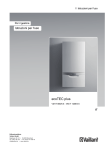
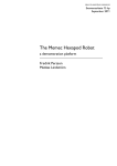
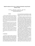
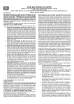
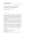
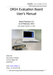
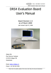
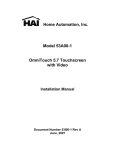
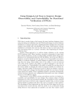
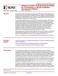
BEEKeeper: Remote Management and Debugging of Large Scale
FPGA Arrays
Terry Filiba, Navtej Sadhal
May 14, 2007
Abstract
but scaling past this level is hindered by the serial nature of the protocol. The Research Accelerator for Multiple Processors (RAMP) project
leverages the low cost of field programmable gate
arrays (FPGAs) to build large, but cheap systems. The project provides a multi-FPGA platform for the emulation of multicore or multiprocessor systems. Large systems, such as RAMP,
struggle with the scalability of JTAG; in an 8
or 16 board system, switching between boards
being accessed via JTAG requires manual connection of the target board to the server running the debug software. The Center for Astronomy Signal Processing and Electronics Research
(CASPER) also builds large scale processors out
of many FPGA boards. These processors need
to be deployed at antennas, but once deployed
cannot easily be debugged remotely.[7]
We propose a solution to the problem of managing and debugging the large array of Berkeley Emulation Engine 2 (BEE2) FPGA boards
which are part of the Research Accelerator for
Multiple Processors (RAMP) project. Currently,
communicating with individual FPGAs on a specific board in the cluster for programming or onchip debugging purposes requires physical access
to the device and the connection of a specialized
communication cable to a host machine. We
have designed and implemented a solution using a soft core on a small FPGA which connects directly to a BEE2 board in the place of
the host computer. The host computer can then
connect to the small unit, the BEEKeeper, over
standard TCP/IP and Ethernet. This allows the
host computer to manage many BEE2 boards siWe propose a system called BEEKeeper that
multaneously without physical access, as well as
will provide remote and scalable JTAG capabilaggregate data from many boards.
ities. Augmenting the current communication
system to use Ethernet rather than parallel connections will improve both scalability and acces1 Introduction
sibility.
In Section 2, we describe the motivation for deThe JTAG protocol has long been a valuable tool
for chip developers and programmers. For board signing this system and projects that can make
level debugging, JTAG chains provide a conve- use of the tool. Section 3 describes other tools for
nient way to connect to a small number of chips, remotely debugging FPGAs and debugging large
1
in RAMP also arise in developing CASPER instruments. Further problems arise when these
instruments are deployed on site. When something goes wrong on a board and can’t be reproduced on a lab bench someone must travel to the
antenna to debug the problem.[5]
systems in general. Sections 4 and 5 explain the
design of the system and how much latency is
introduced. Section 6 proposes a new interface
that makes use of the capability to simultaneously connect to multiple boards. Section 7 provides future plans to improve the analysis and
design of the system. Section 8 describes what
we have learned from building this system.
3
2
Related Work
ChipScopeTM Pro provides a platform for debugging and programming Xilinx FPGAs over
JTAG. It provides some remote connection capability but this capability doesn’t scale well. A
client computer can connect to a server in the
lab that is also running ChipScope. That server
must be connected via a cable to the board.
Since the number of boards that can be connected to a single server doesn’t scale up well this
doesn’t provide a sufficient solution for RAMP
or CASPER.[6]
The architects of the RAMP project have explored various debugging strategies with respect
to processor interaction and logging. Some of
this functionality is planned in the RAMP design
framework, but much of it is dependent upon the
system avoiding total failure [7]. As we attempt
to give the designer complete accessibility to onchip signals and programming, our addition to
the RAMP debugging framework should provide
additional power in such scenarios.
There have also been other efforts at managed
debugging of large-scale systems from a software standpoint. Notably, Fowler, LeBlanc, and
Mellor-Crummey of the University of Rochester
propose an integrated system for debugging parallel programs running on shared-memory multiprocessors [4]. They explore a methodology for
analyzing parallel programs and then develop a
framework for debugging these programs on an
Background
The design of the Berkeley Emulation Engine 2
(BEE2) board at the Berkeley Wireless Research
Center (BWRC) has created a useful platform
for many research projects. This board provides
a large amount I/O and processing power that
is utilized in many multiprocessing applications.
There are four Xilinx Virtex II Pro 70 FPGAs
on the board used for processing and linked by a
single JTAG chain. An additional Virtex II Pro
70 is on the board on a separate JTAG chain
and is primarily used to control the other four
FPGAs.[3]
The RAMP project uses the BEE2 boards for
emulation. Currently the prototype system is
using 8 BEE2s boards but in order to work with
systems that have thousands of cores the number of boards will need to scale greatly. The
demands of this scaling will put a great strain
on the current system of debugging.[7]
The CASPER group develops radio astronomy
tools for phased antenna arrays. Large numbers
of small antennas provide a cheap alternative to
building a single large antenna, but require a
lot of back-end processing to combine the data
from the different antennas. These tools, such as
beam formers and correlators, scale in size based
on the number of the antennas in the array.
The difficulties of scaling that are experienced
2
Chipscope
WinDriver
Parallel
Port
Parallel Cable
Parallel
to JTAG
JTAG Cable
BEE2
Client Computer
Figure 1: Initial debugging architecture. The client computer is connected via a parallel cable to the
BEE2. Components in purple (Parallel to JTAG adapter, Parallel Port, and the portion of WinDriver
that interfaces with the Parallel Port) will need to be removed in order to improve scalability and remote
connection capability.
municating over a parallel cable. Finally, the
JTAG cable is connected to the BEE2 board.
A typical machine only has a few parallel cable ports. To use the remote debugging tools
provided by ChipScope there would need to be a
server for every few boards. In order to provide
scalability, the parallel cable will be removed and
replaced with an Ethernet cable. Referring to
Figure 1, the components in purple must be removed. Removing the parallel cable makes the
parallel to JTAG converter unnecessary. Then,
since ChipScope can no longer communicate over
the parallel port on the computer, part of the
driver must be modified. The interface from
ChipScope to the driver remains the same, but
instead sending data over the parallel port it will
packetize the data and send using TCP/IP over
Ethernet.
Figure 2 shows how the BEEKeeper system
is designed. The WinDriver is modified to interface with an Ethernet port rather than a parallel
port. Then, the Ethernet cable can be connected
to a router and send data over the internet to the
BEEKeeper board. The BEEKeeper board depacketizes the data and sends it out over a JTAG
header.
This is a client-server model in which the com-
SMP machine. This includes monitoring each
processor and keeping replay data and execution
histories to be made available to an engineer at
a single workstation. There are notable developments in the user interface, including scripting capabilities. While hardware and software
debugging differ in many respects, the system
developed by Fowler et. al. provides welcome
inspiration to the problem of debugging large
FPGA arrays.
4
System Architecture
The current method of debugging or programming a BEE2 via ChipScope is described in Figure 1. The client computer runs ChipScope
which provides a graphical interface to the user.
ChipScope communicates with a kernel driver
to send data over a parallel cable connected to
the computer. The kernel driver is produced by
a tool, WinDriver, that automatically produces
source code and a makefile [2]. The parallel cable is connected to a parallel to JTAG adapter.
This is a simple component that just rearranges
the wires from the parallel standard to the JTAG
header. There is no software in this part, and it
is only necessary because the computer is com3
Chipscope
WinDriver
Ethernet
Port
Ethernet
Internet
Ethernet
BEEKeeper
Board
JTAG Cable
BEE2
Client Computer
Figure 2: BEEKeeper debugging architecture. The parallel connection is replaced with an Ethernet cable
and a small board to depacketize the data and translate it into JTAG. Components in yellow (BEEKeeper
Board, Internet, Ethernet Port, and WinDriver interface to the Ethernet Port) are added to the system.
vides the scalability. As long as the servers are
connected to the internet, the client can connect
to any of them by selecting the correct IP address.
We have intercepted the functions that read
and write a byte on the parallel port. Although
the intercepting functions could create and send
a packet, an entire packet just to send a byte of
data is wasteful. Instead, we use a lazy send in
which data that needs to be sent is put into a
queue. The queue will get flushed in two cases.
First, if the buffer to hold stored data is full then
it must get flushed to ensure no data is lost due
to overflow. Also, when ChipScope requests to
receive data, the sent data also must be flushed.
This is to ensure that the data read from the cable is resulting from the input to the chip, and is
due to the fact that ChipScope blocks on reads.
In order to service the requested read, the chip
must be in a state assumed by software. This
also implies that there can only be one outstanding read at any time.
puter running ChipScope is the client and the
BEEKeeper board is the server. The client is in
control in this design and must initiate all communication. The BEEKeeper will be in a wait
loop until the computer initiates communication.
Then the client will either send or request data
until it is finished and closes the connection.
4.1
Client Design
The modifications on the client are all at the
driver level. Because ChipScope is closed source
we could only intercept the data being sent by
ChipScope through the driver. The driver’s
source is available and has been modified to remove the existing parallel port interface.
The driver provides an interface to ChipScope
that allows it to read and write data byte by
byte. The data is taken and put on the parallel port using functions that immediately write
to the hardware; we have altered the hardware
interface of the driver to send data over an Ethernet port instead of a parallel port. Since streams
of data need to be communicated through the
chip, a lossy channel is not appropriate The communication is done over TCP/IP to ensure lossless communication.
The client currently has a software programmed IP address. This aspect is what pro-
4.2
Packet Layout
The JTAG protocol uses very few bit lines to
transmit information due to the fact that everything is done serially. The lines in and out of
the chip are shown in Figure 3(a). Three lines
4
TMS
TDI TDO
TCK
GND VCC
TCP/IP Packets
9
8
7
6
5
4
3
2
1
Ethernet
Port
(a) 9 bit JTAG Header
Spartan-3
MicroBlaze Soft Core
Data sent from client computer to BEEKeeper board
TCP/IP Header
TMS
Data
Divided into 8-bit pieces
blank
TDI
Req.
Data
blank
TCK
blank
blank
Network
Driver
Standalone
Server
Software
Data sent from BEEKeeper board to client computer
blank
blank
blank
TDO
blank
blank
blank
blank
(b) BEEKeeper Packet Format
JTAG Header
JTAG Data
Figure 3: The 9 bit JTAG pin out data in 3(a) and
how it is packetized by the BEEKeeper system 3(b).
Figure 4: Inside the BEEKeeper Board
are used when sending data into the chip: TMS,
TDI, and TCK. TCK clocks the input coming
in on the other wires so the chip can determine
when it is valid. TMS sets the test mode and
TDI contains the test data. The only output
from the chip is TDO whose validity is also determined by TCK.
intermixed in a single packet to try to reduce the
number of packets the client must send.
Packets sent by the server only need to contain
TDO. As Figure 3(b) shows, the single bit, TDO,
is padded out eight bits. While this may seem
inefficient and an obvious point of optimization,
it turns out to be insignificant. Because the request to get data must be serviced before it returns, there can only be one request outstanding at a time, as described in Section 4.1. This
means that a packet can only contain one bit of
TDO. The overhead of using a single packet to
send one bit far outweighs the overhead of the
7 extra bits used as padding in the data. The
TCP/IP header sent along with the single bit is
a much more significant amount of overhead and
as described in Section 7 is a better focus for
optimization.
The packets constructed by the client need to
contain the JTAG information TCK, TDI, and
TMS. Also, it needs a way to distinguish if it is
sending data or requesting to receive a packet. In
a single byte, the JTAG specific data is arranged
in the same order as in the JTAG header (referring to Figure 3). Where the TDO bit would
normally be, there is a request data bit. If this
bit is high then the other data in the byte should
be ignored and the server should read data from
the JTAG port. If the request data bit is low
then the data should be sent to the chip. This
method allows for read and write requests to be
5
4.3
Server Design
to use the JTAG cable. It takes the data from
the packets, 8 bits at a time, and determines
whether it should send or receive data. This is
determined by the request data bit as outlined
in Section 4.2.
One important feature of the server design is
portability. The WinDriver interface with ChipScope is build into the client. This client is only
useful for a board that can use ChipScope as
its JTAG interface. Unlike the client software,
the BEEKeeper server only relies on the packet
format. Although different boards use different
numbers of pins for JTAG, the definition of the
JTAG header send by the BEEKeeper board can
be configured with a packet as well.
The server consists of an Avnet Xilinx Spartan3 Mini-Module board which is referred to as the
BEEKeeper board. This board provides the I/O
necessary to connect an Ethernet cable and a
JTAG cable. The BEEKeeper board has an Ethernet port and 76 pins of I/O directly to the chip,
far more than what is needed for a JTAG header.
The board has a flash memory as well as a configurable Spartan-3 3S400 FPGA [1].
For development purposes, this board has
been mounted on an Avnet Mini-Module Baseboard. The board uses the I/O pins on the
Mini-Module to provide standard forms of I/O
that are useful for development. There is an
LCD, many LEDs and switches, RS-232, and
USB connections as well as JTAG to program
the Spartan-3. This allows us to monitor the I/O
moving between the Ethernet connection and the
JTAG and debug the BEEKeeper system. The
version of the BEEKeeper that would be released
will not include this board.
Figure 4 shows how the BEEKeeper is programmed. A MicroBlaze soft processor core is
put onto the Spartan-3. This allows us to access the I/O channels and program the server
using software. The software implementation
has two components, a driver to communicate
with the Ethernet port and a server that processes the data sent from the client. The network
driver implements the TCP/IP standard similar to the standard functions UNIX networking
drivers provide. The driver provides the framework to establish a TCP connection with the
client and send and receive packets.
The server software waits until a client makes
a connection to it and begins sending data packets. It will loop until it finds valid data to process. Then, the software must determine how
5
Results
We have implemented our system as described
with additional testing and data gathering portions to measure its performance and usability.
The obvious result from running numerous tests
is that the data transmission using the BEEKeeper is much slower than when using the parallel cable directly. This, however, is to be expected due to the additional overhead of packing
up the data, transmitting it over the network,
and then unpacking it again.
5.1
Testing Setup
Our testing setup uses a single BEEKeeper
module connected directly to a host computer
through an Ethernet crossover cable. The host
computer is running RedHat Linux with Linux
kernel 2.6.18. The BEEKeeper is then connected
directly to the target BEE2 board with a ribbon
cable whose signals are visible through a logic analyzer. We collected timing data from the host
6
Figure 5: The frequency distribution of round trip times for data requests by ChipScope for a single bit
from the target
computer using the Linux kernel’s timing fea- reduced to 2.18MHz as measured by a logic analyzer at the connection between the BEEKeeber
tures to measure actual elapsed time.
and the BEE2. This slow down is due only to
the time it takes the processor to unload data
5.2 Speed Measurements
from its buffer, examine it for read requests, and
As expected, the transmission of JTAG data over then send it out on the data line, and does not
TCP/IP with our system is orders of magnitude take into account any network delays that might
slower than direct access with the parallel cable. slow down data even further.
The sources of this slow down include network
Examining the actual flow of data through the
overhead as well as the time it takes to MicroBlaze to process the incoming data and place it on whole system, we found that our clock rate was
the JTAG lines. The latter is dependent on how further reduced to an average of 167kHz. This
the server software on the BEEKeeper is written means that communication over our system is
and results in a hard limit on the top speed at about 30 times slower than it had been over the
parallel cable. This slow down can be attributed
we can transmit data.
When using the parallel cable directly, the to the network overhead and the lack of comclient computer sets the JTAG clock rate to pression in our data stream.
An additional source of delay is the fact that
5MHz, meaning the serial communication occurs
at 5Mbps. The ChipScope software uses timers only one data request by the client computer can
to maintain this rate and thus not violate the be outstanding at any time. That is, every time
setup or hold times of the device being accessed. the client wants to read the TDO line, it must
In contrast, when our server software is running actually request the data from the server. In conon the MicroBlaze processor and transmitting trast, the parallel cable system is always sending
data as fast as possible, the JTAG clock speed is the TDO data on a dedicated wire, so it is al7
access to the ChipScope code to modify the end
to end interface.
By rethinking the interface of the tools, we
can improve debugging for large systems. Since
the tool will communicate over TCP/IP, there is
no longer a need for a kernel level driver. Client
software is sufficient to send data over the Ethernet port. We propose an interface for debugging
multiple boards and some useful applications for
this design.
The system should allow the user to design not
only at the chip level but at the system level.
Instead of specifying the IP address of a single
JTAG chain, multiple chains can be added to allow for communication to different chips simultaneously. Also, it should be possible to group
FPGAs together based on what they do.
In may applications the same programming is
put on many FGPAs. This could be done by
opening connections to many addresses rather
than just one. Then the data that is normally
transmitted to a single FPGA is transmitted to
a group of addresses. This will work as long as
no errors occur, since all of the chips should stay
in the same state. When errors begin to occur,
one data set is no longer appropriate for all the
chips. By creating a new thread to deal with the
failing chip exclusively the rest of the programming is free to proceed unhindered. The new
thread can retry the operation and attempt to
continue normal operation. Then if the problem
is unrecoverable, the system can report a list of
the chips that failed.
This system could also be used to monitor
data running on the FPGAs. By requesting
the same data on the each chip, the exact same
method to program multiple FPGAs can be used
to send the data requests over JTAG. Errors can
be dealt with in the same way as described for
programming. In this case, the output from the
ways there for the client to read it. This slow
down can be expressed by comparing the round
trip time of a data request in our system to the
execution time of a read-byte operation on the
parallel port. Figure 5 shows the distribution
of round trip times seen during JTAG communication. The average round trip time to get a
single bit of data from the TDO line is 1.3ms,
and over 90% of round trips are below 1.5ms.
This time results from all of the previously described sources of delay aside from packet loss
due to network congestion. On the other hand,
the when reading from the parallel port, the data
has already reached the local machine, so it only
takes 1.8µs to read a bit and return it to the
software. This discrepancy is expected because
we are effectively using an entire TCP/IP packet
to send one bit of data.
Regardless of this significant decrease in
speed, the actual effect on debugging interaction, while noticeable, should not actually impact debugging productivity except in the most
extreme cases. Given that Xilinx Virtex II bitfiles are on the order of 1MB, transmitting such
a file at 167kbps would take roughly one minute
rather than being nearly instantaneous as with
the parallel cable.
6
Proposed Debugging Interface
The system we have implemented provides a way
to use the existing ChipScope software in a novel
way. Rather being limited by the number physical parallel ports, a computer now has access to
any board in the system. Currently, the end to
end system appears the same as before; ChipScope connects to a single JTAG chain to program or debug it. Unfortunately, we do not have
8
of data coming from the BEE2 board. If the debugging interface was open source, some of this
could be alleviated. Since the program should
know how much it wants to read from the board,
it can send a request for multiple reads in a single packet or interleaved reads and writes. Then,
when the BEEKeeper board sends a packet back,
it can contain as much data as the program requested.
Finally, we must consider that our experiments have demonstrated that the serial nature
of JTAG and its chattiness make it somewhat
unsuitable for network transmission. Given this,
it may be desirable to develop a more advanced
device than our BEEKeeper, which will actually
receive bulk data in a different format and then
generate the JTAG signals locally. Such a system would require understanding of the JTAG
protocol as well as the development of a communications interface that supports higher level
communications. In some respects, this might
work like the previously described remote ChipScope ability that already exists. However, replacing the computer connected directly to the
board with an embedded system significantly improves scalability and packaging by allowing said
system to be integrated entirely on the board.
While this might drive up costs, it is worth exploring in effort to increase the power, flexibility,
and speed of the debugging system.
chips also needs to be logged. It can be recorded
and viewed either by focusing on a single chip or
viewing the data from multiple chips that was
generated at the same time.
7
Future work
This work can be further explored in a number
of ways. Further benchmarking would be useful,
as well as some updates to improve the system.
Also, it would be useful to find ways to reduce
the overhead of packetizing and processing the
data, either by
Section 5 gives results from timing tests done
in a lab to see how using the TCP/IP overhead
slows down JTAG speed. These tests do not account for network effects like dropped packets or
Additional tests would be useful to get an idea
of how a system like this could be used across
longer distances and on lossy networks.
The BEEKeeper board was chosen because it
is cheap and small. However, there isn’t a need
for the board itself. We could integrate the necessary parts of the BEEKeeper onto the board
that is being debugged. This would only require
an Ethernet port, an FPGA, and a small memory to store the programming. Then, rather than
having pins coming out of the board, the connection between the BEEKeeper hardware and the
FPGA can be wired on the board. Integrating
this hardware onto the board will create a small
cost increase in the board but will ease debugging.
Additionally, we would like to implement the
debugging interface described in Section 6. This
would give the user better control of the system
as a whole as explained. Also, this could allow
for optimization benefits as well. Currently, the
system has to use a whole packet for a single bit
8
Conclusion
We have presented and evaluated a remote and
scalable system targeted to programming and
debugging BEE2 boards. This is achieved by
modifying the communication between ChipScope and and the JTAG interface to the board.
Because ChipScope is closed source, we intercept
9
the data bound for the parallel port at the driver
level and reroute the data to the computer’s Ethernet port. Using the TCP/IP standard allows
the data to be transmitted through the Internet and arrive at our intermediate hardware, the
BEEKeeper. The BEEKeeper is a small board
that receives the packets and processes them into
JTAG. This board essentially interfaces one of
the BEE2 JTAG chains to the network.
We did find additional latency, as expected,
from migrating from a nearly lossless channel
(the parallel port) to TCP/IP over Ethernet in
our testing. Also, the fact that we could not
modify ChipScope created additional inefficiencies. Any reads from the JTAG cable requested
by ChipScope have to be serviced immediately.
Because of this, we must use an entire packet
just to send one bit. We believe that this reduction in speed, while significant, will have little
effect on the debugging efficiency of an engineer
because of the small amount of data that is actually communicated.
We believe that by modifying the user interface for connecting to the chip, improvements
both in debugging capability and communication latency will result. By queueing up multiple receive requests in the same packet, a single
packet coming from the BEEKeeper board could
be used to service all of the read requests.
Aside from this, we believe there is plenty of
room for future work in improving this communication link and reworking the user interface and
debugging software. We have laid the groundwork for future innovations in working with large
systems make necessary by projects like RAMP
and CASPER. As large systems begin to build
momentum, methods for the debugging of large
FPGA arrays and other immensely parallel devices should mature far beyond what we have
discussed here.
References
[1] Spartan-3 mini module user guide. Technical
report, Memec, 2005.
[2] WinDriver USB v9.00 User’s Manual, 2007.
[3] Chen Chang, John Wawrzynek, and
Robert W. Brodersen. BEE2: A high-end
reconfigurable computing system.
IEEE
Design & Test, 22(2), 2005.
[4] Robert J. Fowler, Thomas J. LeBlanc, and
John M. Mellor-Crummey. An integrated
approach to parallel program debugging and
performance analysis onlarge-scale multiprocessors. ACM SIGPLAN Notices, 24(1),
1989.
[5] Aaron Parsons, Donald Backer, Chen
Chang, Daniel Chapman, Henry Chen,
Patrick Crescini, Christina de Jesus,
Chris Dick, Pierre Droz, David MacMahon, Kirsten Meder, Jeff Mock, Vinayak
Nagpal, Borivoje Nikolic, Arash Parsa,
Brian Richards, Andrew Siemion, John
Wawrzynek, Dan Werthimer, and Melvyn
Wright. Petaop/second FPGA signal processing for SETI and radio astronomy.
Proceedings of the Asilomar Conference on
Signals, Systems, and Computers., 2006.
[6] Brent Przybus.
Un-tethered debugging.
Technical report, Xilinx, Inc., 2005.
[7] John Wawrzynek, Mark Oskin, Christoforos
Kozyrakis, Derek Chiou, David A. Patterson, Shih-Lien Lu, James C. Hoe, and Krste
Asanovic. RAMP: A research accelerator for
multiple processors. Technical report, University of California at Berkeley, 2006.
10