1
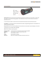
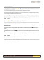
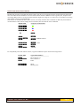
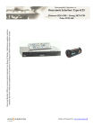
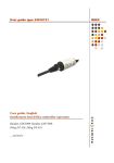
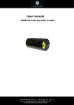
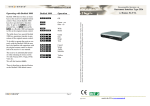
OneRemote converter
Type 34016150
User Manual
Operate with Beolink
Humax
BXR-HD
34016150u1uk
Everyday use
OO
Playback & Recording
OK
o
o0
Q*1
E*1
W*1
R*1
TV-guide
Back
P+
P-
o1
o3
TV-Radio
Media
List
e
Exit
o2
qq
oq
Play press 1 sek
Play alternative
Stop
Pause
oAS
Next, previous
Rew, FF
o8
Record
oDF
Other operations
*1 As the un-shifted function of the coloured function buttons has
been assigned to other functions, they have to be preceded with a
O to retrieve their actual coloured functions.
o7
o9
Text receiver internal
Menu alternativ
Subtitle
info
Power on/ off
oQ
oW
oE
oR
oe
Opt+
o4
o5
o6
Green function
Yellow function
Red function
Blue function
Operating using a Beolink 1000 or other old remote controllers.
Older remote controls do not have coloured buttons, and use is
not logical.
As Beolink 1000 has no coloured buttons the
Zapmode option needs to be set, to make the
the up/ down arrows serve as P+ and P-.
See page 6 about option programming.
The P button on older Bang & Olufsen remote controls
does the exact same operation as theObutton on never
remote controls.
www.oneremote.dk
g
x
pg
Back
Exit
Guide
phZ
phX
phC
phV
Green function
Yellow function
Blue function
Red function
Page 1
Congratulations.
The BEE2 converter from www.oneremote.dk can fully operate your device using your Bang
& Olufsen remote control terminal, in a beelink system.
Beo4 Beo5 or Beo6 remote controls can be used. Beolink 1000 can be used with reduced
functionality. This guide explains how.
This converter is ready for use, plug & play. See the opposite page regarding daily operation.
Some operations can be altered, to improve interaction with other controllers or to your
convenience. Refer to the installation section further on, if changes are needed.
www.oneremote.dk
Page 2
List of Contents
Beo4/ Beo5 Translation table ................................................................................
beeLINK basics .......................................................................................................
beeLINK2 installation .............................................................................................
beeLINK2 connections ...........................................................................................
Programming Zap option .......................................................................................
Menu option ..........................................................................................................
Beolink 1000, Beo4, Beo5 and Beo6 .....................................................................
Beelink Active option .............................................................................................
www.oneremote.dk
page
page
page
page
page
page
page
page
1
4
5
7
8
8
9
10
Page 3
beeLINK basic
The IR data emitted from a Bang & Olufsen remote control, is captured with a IR-receiver. If there is already
one IR-receiver in the room, this can also be used to feed the BeeLINK bus. Normally there is no need for
two IR receivers in the same room.
Data received by the IR-receiver is fed to a OneRemote Link Amplifier with built-in power supply and 5
outputs for beeLINK devices.
If there is more than 5 beeLINK devices in the setup, splitters can be added.
The BeeLINK bus distributes the IR-data, received with the attached IR-receiver from a Beolink 1000, Beo4
or Beo5 to any number of beeLINK controllers. It also supplies the attached controllers with power.
The cable used between the link amplifier and the controllers is simple CAT5 type cable with RJ45 plugs.
This type of cable is inexpensive and a standard cable that any installer are familiar with. Also it is well
suited for data transmission. Finally many modern house installations use the same connectors, making
installation even easier.
Note !
A BeeLINK bus must ONLY be connected to other beeLINK components.
If connected to LAN or other systems, there is a great risk to damage these systems.
The BeeLINK bus is a parallel bus type. Passive splitters therefore can be used, to make a network of any
shape. If many controllers or very long cables are used, it might be necessary to add more power supplies.
Using this parallel structure each beeLINK controller receives the IR-data simultaneously. Every controller
has its own microcomputer, living its own life.
Although some of the controllers can ‘talk’ to each other, most controllers operates fully on their own.
www.oneremote.dk
Page 4
beeLINK2 installation
The beeLINK2 controller gets its power supply and control data, via the CAT5 cable from a beeLINK
amplifier. The beeBus.
Once connected to the beeBUS the beeLINK2 controller only needs an IR-emitter to operate the device it
has been designed for. The IR-emitter emits the same IR data as the device’s own remote control.
Emitted IR data is in fact pure light at a frequency just out of the spectrum that the human eye is able to see.
It emits short flashes of light, a bit like when sending Morse codes using a flashlight.
The beeLINK2 controller can be placed by the device or in another room. IR
emitters are available in lengths of 1, 5 and 10 meters. Additional extension
cords can be used. An IR-emitter can be extended to more than 50 meters.
The IR-emitter can be placed inside the device, if you want to avoid having it
on the outside, as long as the IR-receiver is able to see the light from the
emitter. This requires that the device is opened and the emitter is placed
inside.
The converted IR data is transmitted to the
receiver’s ir-receiver via a small IR-emitter
that has to placed in front of the device to be
controlled.
Here it emits the same IR data into the front
of the device, that it was made to receive
from its own remote control.
www.oneremote.dk
Page 5
A beeBUS CAT5 cable may exceed more than 75 meters without additional amplifiers.
Some beeLINK2 controllers requires not only a simple IR-emitter, to operate a device. If the device is not
able to power on and off via separate commands, the beeLINK controller needs to measure the power
status of the device.
This is done using special IR-emitters that either measures the status signal on a TV-scart output or the
presence of a video signal.
OneRemote 81108180 IR-emitter cable.
Measures the DC-status on a Scart TV-output.
OneRemote 31108182 IR-emitter cable.
Measures the presence of a video output signal.
The Humax BXR-HD receiver cannot be powered on and off using discrete codes and does not cut of video
and status signalling, when in standby.
Therefore this receiver can only be powered on and off using the o9 command. Usually the
receiver is never powered off, so this is not a problem.
The correct IR-emitter for this BEE2 converter is therefore a simple type like the 81108110:
www.oneremote.dk
Page 6
Bee2 connections
The IR/ sense socket is output for the IR-emitter that sends IR to the device to be operated. In some cases
this socket is also used for sensing purposes. Some BeeLINK2 converters needs to know if the device is
powered up or not.
In some cases this socket is used for other serial communications like RS-232 instead of IR control.
Prog switch is a push button that must be activated to initiate a programming sequence, as described in the
option programming chapters.
Do not use socket is for firmware updating of the controller, and connection to special adapters. If used for
anything else, the controller will be damaged.
LED indicates different operating states:
Red-green flash:
Red flash:
Red:
Green:
Short off:
No data has been received since power has been applied
The controller is in option programming mode.
The controller is active.
The controller is inactive.
When the controller sends data, the LED turns off 1 sec.
www.oneremote.dk
Page 7
Programme Zapping option
In a BeeLINK environment the buttonsW and Rare being used for programme stepping and to manoeuvre
up and down in an on screen menu.
This is the basic OneRemote layout and compatible with other OneRemote controllers.
Some people prefer the programme zapping buttons on the up and down buttons. The programme zapping option,
make it possible to change the function of these buttons.
If the user would give it a fair chance, trying out the OneRemote layout, it is not likely that he would make use of this
option. The OneRemote layout adds much perspective to many OSD menus on many devices, and makes sense once
fully understood. But we are up against habits, which we all wants to hang on to, so...
Option
Function
090
091
W andRare used for Bouquet+/ Bouquet-. Factory setting.
D andFare used for Bouquet+/ Bouquet-.
An option programming sequence is initiated by pressing the little red switch on the BeeLINK2 controller, until its LED starts flashing. Hereafter the
3 digit option code must be entered with the B&O remote control.
Menu button option
If the device is used in a setup that includes a Bang & Olufsen TV, sometimes the use of the m button gives a
conflict.
Some Bang & Olufsen TV act on the m and enters its own TV On Screen Menu regardless of which source it is set
to.
In these setups the Menu button must be disabled on the BeeLINK controllers. Instead of using the Menu button to
access the devices ‘Menu’, use the alternative menu operation o5.
Option
Function
080
081
Menu button blocked. Use alternative menu operation
Menu button enabled.
An option programming sequence is initiated by pressing the little red switch on the BeeLINK2 controller, until its LED starts flashing. Hereafter the 3
digit option code must be entered with the B&O remote control.
www.oneremote.dk
Page 8
Beolink 1000, Beo4, Beo5 and Beo6.
Beolink 1000 and other early Bang & Olufsen remote controls are not equipped with the coloured function buttons that
have been added to Beo4 and Beo5. The lack of these buttons makes it difficult to make a good layout, transparent for
controlling different devices. Some operations therefore might be less logical or in some cases not available, when using
older remote controls in a beeLINK setup.
Some buttons on the Beolink 1000 remote controls, do actually send the same commands as differently named buttons
on a Beo4/ Beo5. Other buttons simply has been renamed, but still sends the same commands.
Beolink 1000
Compares to Beo4/ Beo5
-------------------------------------------------hZ
Q
hX
W
hC
R
hV
E
o
P
v
hv
s
T
hs
ht
y
hy
d / CDV
a
VTAPE2 /VMEM2 /DVD2
f
b
AMEM2
For compatibility with older remote controls, a typical OneRemote layout uses the following buttons:
Beolink 1000
---------------g
pg
x
Typical BeeLINK use
----------------------------------------Back, Backup e.t.c.
EPG, Guide e.t.c.
EXIT.
p5
p9
Menu.
Manual power.
www.oneremote.dk
Page 9
BeeLINK Active option.
As all converters on the BeeLINK bus are receiving the IR-data simultaneously, every controller must know when to go
active and when to go inactive. Sometimes two or more controllers are active at the same time.
A BeeLINK 2 controller is used to operate a TV, a satellite receiver, a DVD-player, a projector or similar devices. Each
controller is specifically made for one device.
From factory a BeeLINK2 controller is set to go active on a source button like t or d. The controller can be
programmed to go active on another source, setting the Active option.
Your BeeLINK2 controller needs to know when you want it to go active, in your setup. You need to program it with an
Active option.
Option
Function
f0r
f1r
f2r
f turns on the receiver. (Factory setting for this converter.)
f + 1 turns on the receiver.
f + 2 turns on the receiver.
An option programming sequence is initiated by pressing the little red switch on the BeeLINK2 controller, until its LED starts flashing. Hereafter the
3 digit option code must be entered with the B&O remote control.
Up to 10 receivers can be controlled this way, using the same source. This could be useful when you have more than
one device of the same type.
When the BeeLINK2 controller goes active, its LED will turn red to indicate this. When another source is selected, the
controller will go inactive and the LED turn green.
As a controller goes active, it will usually turn on the device, if it is not already turned on.
A setup with 3 receivers attached to both a TV
and a projector.
An example of operation could be:
t1
t2
f1
f2
T
www.oneremote.dk
Operate projector
Operate TV
Operate DVB-S
Operate DVB-T
Operate DVB-C
Page 10