1
TECHNICAL DATASHEET #TDAX030530
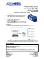
1 Universal Signal Input
CAN Controller (SAE J1939)
with Electronic Assistant®
P/N: AX030530
Distributed I/O for Engine Control Systems
Features:
•
•
•
•
•
•
1 universal signal input
(Voltage, Current, Resistive, Digital, Frequency or PWM)
User selectable input range from: 0-1V; 0-2.5V; 0-5V; 0-10V; 020mA; 4-20 mA; 20 Ohm to 250 kOhm (Auto Range or User
Selectable Ranges); 10Hz – 1 kHz; or 100 Hz – 10 kHz.
12V/24/48VDC input power (nominal) with transient and reverse
polarity protection
1 CAN (SAE J1939), CANopen® on request
Rugged packaging and connectors
Electronic Assistant®
runs on a Windows operating system
for user configuration and programming. An Axiomatic USB-CAN
links the PC to the CAN bus.
Applications:
•
•
Distributed controls for power generation, co-generation, stationary power
Distributed controls for commercial vehicles, off-highway equipment, industrial equipment, etc.
The controller belongs to a family of Axiomatic smart controllers with programmable internal architecture. This
provides users with flexibility, allowing them to build their own custom controller with a required functionality from a set
of predefined internal functional blocks using the PC-based Axiomatic Electronic Assistant® software tool. Application
programming is performed through the CAN interface, without disconnecting the controller from the user’s system.
Ordering Part Numbers:
SAE J1939 version
Controller: AX030530
Mating Plug Kit: AX070112 (Comprised of DT06-8SA, W8S, 7 pcs. 0462-201-16141, 1 pc. 114017)
AX070502 Configuration KIT includes the following.
USB-CAN Converter P/N: AX070501
1 ft. (0.3 m) USB Cable P/N: CBL-USB-AB-MM-1.5
12 in. (30 cm) CAN Cable with female DB-9 P/N: CAB-AX070501
AX070502IN CD P/N: CD-AX070502, includes: Electronic Assistant® software; EA & USB-CAN User Manual
UMAX07050X; USB-CAN drivers & documentation; CAN Assistant (Scope and Visual) software & documentation;
and the SDK Software Development Kit. NOTE: To order this kit, you need only to specify P/N: AX070502.
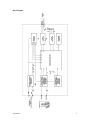
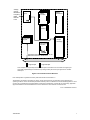
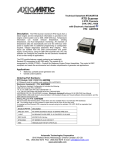
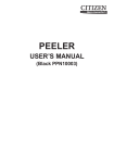
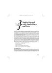
Block Diagram
TDAX030530
2
Technical Specifications:
Input Specifications
Power Supply Input - Nominal
Protection
Universal Signal Input
Ground Connection
12V or 24VDC or 48VDC nominal (9…60 VDC power supply range)
Transient and reverse polarity protection is provided.
1 universal signal input (user selectable)
(Voltage, Current, Resistive, Digital, Frequency or PWM)
Refer to Table 1.0.
1 Analog GND connection is provided.
Table 1.0 – Input – User Selectable Options
Analog Input Functions
Voltage Input, Current Input or Resistive Input
Voltage Input
0-1V (Impedance 1 MOhm)
0-2.5V (Impedance 1 MOhm)
0-5V (Impedance 204 KOhm)
0-10V (Impedance 136 KOhm)
Current Input
0-20 mA (Impedance 124 Ohm)
4-20 mA (Impedance 124 Ohm)
Resistive Input
Range: 20Ω to 250 kΩ (Auto Range)
User-selectable ranges:
0…150 Ω
0…800 Ω
0…2.5 kΩ
0…8 kΩ
0…25 kΩ
0…80 kΩ
0…250 kΩ
Digital Input Functions
Digital Input
Input Impedance
Discrete Input, PWM Input, Frequency Input
5V CMOS compatible
0 to 100%
10 Hz to 1kHz
100 Hz to 10 kHz
10 Hz to 1kHz
100 Hz to 10 kHz
Active High, Active Low
1 MOhm high impedance, 10KOhm pull down, 10KOhm pull up to +5V
Input Accuracy
Input Resolution
< 1%
12-bit
Digital Input Level
PWM Input
Frequency Input
Output Specifications
Output
CAN Messages, SAE J1939
{CANopen® available on request}
Refer to Control Logic and Figure 1.0 as well as the user manual for details.
CAN
The Electronic Assistant® (EA) is used to set up CAN signal acquisition and
processing algorithms.
The controller can send a single frame application specific CAN message to the
network continuously or on request. Using the EA, the user can configure this
feature.
General Specifications
Microprocessor
Control Logic
CAN
Slew Rate
User Interface (PC-based)
TDAX030530
32-bit, 128 KByte flash program memory
Standard embedded software is provided. Refer to Figure 1.0.
(Application-specific control logic or factory programmed setpoints are available on
request.)
The controller belongs to a family of Axiomatic smart controllers with
programmable internal architecture.
This provides users with an ultimate
flexibility, allowing them to build their own custom controller with a required
functionality from a set of predefined internal functional blocks using the PC-based
Axiomatic Electronic Assistant® software tool. Application programming is
performed through CAN interface, without disconnecting the controller from the
user’s system.
1 CAN port (SAE J1939) (CANopen® on request)
To adjust the controller to the CAN physical network, the slew rate can be
configured as fast or slow. Refer to the User Manual for details.
The controller setpoints can be viewed and programmed using the standard J1939
memory access protocol through the CAN port and the PC-based Axiomatic
3
Electronic Assistant®. For default setpoints, refer to the User Manual. The EA
can store all controller setpoints in one setpoint file and then flash them into the
controller in one operation. The setpoint file is created and stored on disk using a
command Save Setpoint File from the EA menu or toolbar. The user then can
open the setpoint file, view or print it and flash the setpoint file into the controller.
The Electronic Assistant® for Windows operating systems comes with a royaltyfree license for use on multiple computers. It requires an Axiomatic USB-CAN
converter to link the device’s CAN port to a Windows-based PC.
Typical Current Draw
Weight
Operating Conditions
Protection
Packaging and Dimensions
P/N: AX070502, the Axiomatic Configuration KIT includes the following.
USB-CAN Converter P/N: AX070501
1 ft. (0.3 m) USB Cable P/N: CBL-USB-AB-MM-1.5
12 in. (30 cm) CAN Cable with female DB-9 P/N: CAB-AX070501
AX070502IN CD P/N: CD-AX070502, includes: Electronic Assistant® software;
EA & USB-CAN User Manual UMAX07050X; USB-CAN drivers & documentation;
CAN Assistant (Scope and Visual) software & documentation; and the SDK
Software Development Kit.
25 mA @ 12V
14 mA @ 24V
8.5 mA @ 48V
Conditions: Resistance Input, 0…150Ω, CAN output transmission every 100ms.
0.65 lbs. (0.29 kg)
-40 to 85 °C (-40 to 185 °F)
IP67
PCB is conformal coated and protected by the housing.
Encapsulated
Cast Aluminum housing with mounting holes
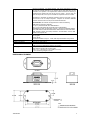
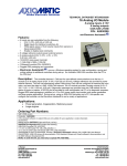
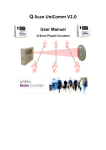
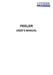
4.62 x 1.91 x 1.76 inches (117.30 x 48.56 x 44.73 mm)
L x W x H including integral connector
DIMENSIONAL DRAWING
TDAX030530
4
Mounting
Mounting holes – The controller accepts 2 #10 or M4 screws.
The CAN wiring is considered intrinsically safe. The power wires are not
considered intrinsically safe and so in hazardous locations, they need to be
located in conduit or conduit trays at all times. The module must be mounted in an
enclosure in hazardous locations for this purpose.
All field wiring should be suitable for the operating temperature range.
Network Termination
Install the unit with appropriate space available for servicing and for adequate wire
harness access (6 inches or 15 cm) and strain relief (12 inches or 30 cm).
It is necessary to terminate the network with external termination resistors. The
resistors are 120 Ohm, 0.25W minimum, metal film or similar type. They should
be placed between CAN_H and CAN_L terminals at both ends of the network.
Electrical Connections
Deutsch DT series 8 pin plug (DT15-8PA)
Mating plug KIT: Axiomatic P/N AX070112
(Comprised of Deutsch IPD P/n’s: DT016-8SA socket, wedge W8S, 7 solid
contact sockets 0462-201-16141 and 1 sealing plug 114017.)
16-18 AWG wire is recommended for use with sockets 0462-201-16141.
Use dielectric grease on the pins when installing the controller.
Wiring to these mating plugs must be in accordance with all applicable local codes.
Suitable field wiring for the rated voltage and current must be used. The rating of
the connecting cables must be at least 70°C. Use field wiring suitable for both
minimum and maximum ambient temperature.
PIN #
1
8
2
7
3
6
4
5
TDAX030530
FUNCTION
Power +
Power CAN Shield
NOT USED
CAN HI
AGND
CAN L
ANALOG SIGNAL INPUT
5
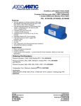
Control Logic
From the software prospective, the controller consists of a set of internal functional blocks, which can be
individually programmed and arbitrarily connected together to achieve the required system functionality. See
Figure 1.
Each functional block is absolutely independent and has its own set of programmable parameters, or
setpoints. The setpoints can be viewed and changed through CAN using the Electronic Assistant®.
There are two types of the controller functional blocks. One type represents the controller hardware
resources, for example the analog signal input block. The other type is purely logical – these functional blocks
are included to program the user defined functionality of the controller. The number and functional diversity of
these functional blocks are only limited by the system resources of the internal microcontroller. They can be
added or modified on the customer’s request to accommodate user-specific requirements.
The user can build virtually any type of a custom control by logically connecting inputs and outputs of the
functional blocks. This approach gives the user an absolute freedom of customization and an ability to fully
utilize the controller hardware resources in a user’s application.
Each functional block of the controller is presented by its own folder in the Setpoint File root folder in the
Electronic Assistant®.
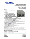
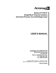
By default, the output of the Universal Input functional block is connected to the first logical input of the CAN
Output Message functional block, as shown in Figure 1. It provides the simplest controller configuration, when
the signal from the input is directly routed to the CAN output.
When additional processing of the input signal is required, the user can use logical functional blocks provided
with the controller. There are five Binary Function, two Conversion Function, and two PID Control functional
blocks available for this purpose in the current version of the embedded software. The detailed description of
the functionality of these functional blocks can be found in the user manual.
TDAX030530
6
Voltage,
Current,
Resistance,
Frequency,
PWM,
Discrete
Level
Universal
Input
Binary
Function
Global
Parameters
PID
Control
CAN
Output
Message
CAN Input
Signal
Conversion
Function
The default controller configuration can be
different from the one shown here.
J1939 CAN Bus
Logical Input
Logical Output
As an example, the logical output of the Universal Input functional block is connected to the logical input
of the CAN Output Message functional block, providing a direct path for the input signal to the controller
CAN output.
Figure 1.The Controller Internal Structure
Note: CANopen® is a registered community trade mark of CAN in Automation e.V.
Specifications are indicative and subject to change. Actual performance will vary depending on the application and
operating conditions. Users should satisfy themselves that the product is suitable for use in the intended application. All our
products carry a limited warranty against defects in material and workmanship. Please refer to our Warranty, Application
Approvals/Limitations and Return Materials Process as described on www.axiomatic.com/service.html.
Form: TDAX030530-10/14/10
TDAX030530
7