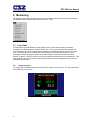
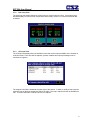
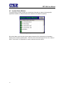
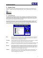
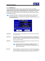
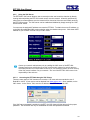
1
EZTEZT-560i
Environmental Chamber Controller
User Manual
EZT560i User Manual revB.doc
EZT-560i User Manual
TABLE OF CONTENTS
1.
Overview… ........................................................................................................ 5
1.1 Safety Information................................................................................................................. 5
1.1.1 Device Under Test (DUT) Safety Information................................................................. 5
1.2 About the EZT-560i............................................................................................................... 6
1.3 Touch Screen Interface ........................................................................................................ 7
1.3.1 Menu Navigation............................................................................................................. 8
1.4 Print Features ..................................................................................................................... 11
2.
Monitoring ....................................................................................................... 12
2.1 Loop Views ......................................................................................................................... 12
2.1.1 Single Loop View .......................................................................................................... 12
2.1.2 Dual Loop View............................................................................................................. 13
2.1.3 All Loops View .............................................................................................................. 13
2.2 Trending.............................................................................................................................. 14
2.3 Alarm Monitor ..................................................................................................................... 16
2.3.1 Pumpdown.................................................................................................................... 16
2.4 Alarm History ...................................................................................................................... 17
2.5 System Status Monitor........................................................................................................ 18
3.
Manual Operation ........................................................................................... 19
3.1 Setpoint Adjustment............................................................................................................ 19
3.2 Event Control (Turning the Chamber On/Off).................................................................... 20
3.2.1 Standard Chamber Options.......................................................................................... 20
3.2.1.1 Humidity Operation ............................................................................................ 20
3.2.1.2 Auxiliary Cooling Operation ............................................................................... 22
3.2.1.3 Dry Air Purge/Low RH Operation....................................................................... 22
3.2.2 Special Chamber Options............................................................................................. 23
3.2.2.1 Altitude Operation .............................................................................................. 23
3.2.2.2 Thermal Shock Transfer Mechanism Operation................................................ 23
3.2.2.3 Defrost Operation............................................................................................... 24
3.2.2.4 Remote Setpoint Operation ............................................................................... 24
3.2.3 Product Control Option ................................................................................................. 24
3.2.4 Customer Events Option............................................................................................... 24
3.3 One-Touch Tuning.............................................................................................................. 25
4.
Profile Operation............................................................................................. 26
4.1 Profile Entry ........................................................................................................................ 27
4.1.1 Selecting Step Events................................................................................................... 28
4.1.2 Selecting Guaranteed Soak (GS) Events ..................................................................... 28
4.1.3 Using Wait For .............................................................................................................. 29
4.1.4 Setting Setpoints and Step Time .................................................................................. 30
4.1.5 Using Jumps ................................................................................................................. 31
4.2 Autostart ............................................................................................................................. 32
4.3 Guaranteed Soak Limits ..................................................................................................... 33
4.4 Plot Profile .......................................................................................................................... 34
4.5 Start/Stop Profile................................................................................................................. 35
4.5.1 Hold/Resume a Profile.................................................................................................. 36
4.5.2 Advance Previous/Next Step........................................................................................ 36
4.5.3 Adjusting Step Time...................................................................................................... 36
4.6 Profile Status View.............................................................................................................. 37
4.7 Profile Worksheet ............................................................................................................... 38
4.8 Frequently Asked Questions About Profiles....................................................................... 39
2
EZT-560i User Manual
TABLE OF CONTENTS (cont'd)
5.
Chamber Setup ............................................................................................... 41
5.1 Power Recovery ................................................................................................................. 41
5.2 Setpoint Limits .................................................................................................................... 42
5.3 Event Tagnames................................................................................................................. 43
5.4 Process/Alarm Tagnames .................................................................................................. 44
5.5 Alarm Settings .................................................................................................................... 45
5.6 Product Control................................................................................................................... 47
5.6.1 Using Product Control................................................................................................... 48
5.6.1.1 Should I Use Product Control for My Test ......................................................... 48
5.6.1.2 Implementing Product Control on “Dead Loads” ............................................... 49
5.6.1.3 Implementing Product Control on “Live Loads” ................................................. 50
5.6.1.4 Considerations When Applying Product Control ............................................... 51
5.7 Condensation Control ......................................................................................................... 52
5.8 Defrost Settings .................................................................................................................. 53
5.9 Web Server/Modbus/VNC .................................................................................................. 54
5.10 Email ................................................................................................................................... 55
5.10.1 Address Entry ............................................................................................................... 55
5.10.2 Email Addresses........................................................................................................... 56
5.10.3 Email Settings............................................................................................................... 56
6.
Security…. ....................................................................................................... 58
6.1 Security Setup .................................................................................................................... 59
6.1.1 Add User....................................................................................................................... 59
6.1.2 User List........................................................................................................................ 59
6.1.2.1 Delete User ........................................................................................................ 60
6.1.2.2 Change User Password..................................................................................... 60
6.1.3 User Rights ................................................................................................................... 60
6.1.4 Security Options ........................................................................................................... 61
6.2 User Log On/Off.................................................................................................................. 62
6.3 View Audit Trail................................................................................................................... 62
6.4 Current User ....................................................................................................................... 62
7.
Logging…. ....................................................................................................... 63
7.1 Start/Stop Logging .............................................................................................................. 64
7.2 Select Points for Logging.................................................................................................... 65
7.3 History Files ........................................................................................................................ 66
7.3.1 Accessing History Files................................................................................................. 66
7.3.2 View History Plot........................................................................................................... 66
7.3.2.1 History Plot Time Setup ..................................................................................... 67
7.3.2.2 History Plot Channel Setup................................................................................ 68
7.3.3 View Averages Report .................................................................................................. 68
7.4 File Utilities ......................................................................................................................... 69
7.5 FTP\WAN Setup ................................................................................................................. 71
3
EZT-560i User Manual
TABLE OF CONTENTS (cont'd)
8.
System Maintenance ...................................................................................... 73
8.1 Degrees C\F Selectio.......................................................................................................... 74
8.2 Service Monitors ................................................................................................................. 75
8.2.1 Service Info Setup ........................................................................................................ 76
8.3 Set Date\Tim....................................................................................................................... 77
8.3.1 Time Options ................................................................................................................ 77
8.3.2 DST Settings................................................................................................................. 78
8.4 Touch Screen Calibration ................................................................................................... 79
8.4.1 LCD Settings................................................................................................................. 81
8.5 Special Settings .................................................................................................................. 82
8.6 I/O ....................................................................................................................................... 83
8.6.1 Control Inputs ............................................................................................................... 83
8.6.2 Monitor Inputs ............................................................................................................... 83
8.6.3 Analog Inputs................................................................................................................ 84
8.6.3.1 Analog Input Wiring............................................................................................ 84
8.6.3.2 Enabling Remote Setpoint Inputs ...................................................................... 85
8.6.4 Analog Outputs ............................................................................................................. 86
8.6.4.1 Analog Output Wiring......................................................................................... 87
8.6.5 Digital Inputs ................................................................................................................. 88
8.6.5.1 Digital Input Wiring............................................................................................. 90
8.6.6 Digital Outputs .............................................................................................................. 91
8.6.6.1 DUT Safety Relay Output Wiring ....................................................................... 92
8.6.6.2 Digital Output Wiring.......................................................................................... 92
9.
Communications............................................................................................. 94
9.1 Serial Communications....................................................................................................... 95
9.1.1 Adjusting Modbus Serial Communication Settings....................................................... 95
9.1.2 EIA-232 Connections.................................................................................................... 96
9.1.3 EIA-485 Connections.................................................................................................... 97
9.2 GPIB (IEEE-488) Communications .................................................................................... 99
9.2.1 GPIB Command Structure .......................................................................................... 100
9.3 Ethernet Communications ................................................................................................ 101
9.3.1 Guidelines of Smart Networking Practice ................................................................... 102
9.3.2 Obtaining the EZT-560i’s MAC Address..................................................................... 103
9.3.3 Setting a Static IP Address......................................................................................... 103
9.3.4 Using the Web Server................................................................................................. 107
9.3.5 Using the VNC Server ................................................................................................ 109
9.3.5.1 Accessing the EZT-560i through a VNC Viewer.............................................. 109
10. Diagnostics ................................................................................................... 111
10.1 Alarm Codes and Troubleshooting ................................................................................... 111
10.2 Service Monitors ............................................................................................................... 115
Appendix
Common Terms and Definitions
List of Figures
4
EZT-560i User Manual
1. Overview
This manual has been tailored to cover all of the specific features and options available on the EZT560i environmental chamber controller. Note that all options and/or features may not be available for
your particular chamber. It is highly recommended that you read this manual thoroughly and
understand all aspects of the EZT-560i’s controller prior to operating your chamber.
1.1
Safety Information
Note, caution and warning symbols that appear throughout this manual are to draw your attention to
important operational and/or safety information.
A “NOTE” marks a short message to alert you to an important detail.
A “CAUTION” safety alert appears with information that is important for protecting your
equipment and performance.
A “WARNING” safety alert appears with information that is important for protecting you,
others and equipment from damage. Pay very close attention to all warnings that apply to
your chamber.
1.1.1 Device Under Test (DUT) Safety Information
The environmental chamber is equipped with high heat limits and/or safety devices. These devices
are installed to protect the chamber from exceeding design limits. These devices remove power from
the chamber’s heaters ONLY and DO NOT remove power from the device under test.
Provisions must be made by the end user to de-energize the tested device with the chamber in order
to prevent an over-temperature condition and subsequent damage to the chamber and/or device
under test. For this reason, the chamber is equipped with a DUT safety relay (24V AC/DC, 6A
maximum resistive load) that should be connected to the device’s power supply control circuit at a
minimum. This relay will open and de-energize the device under test to prevent a runaway thermal
condition whenever the chamber is not operating. (See Section 8.6.6.1, DUT Safety Relay)
Main Supply
L1
L2
fuse
mechanical
contactor
DUT
safety
relay
24V supply
coil
Figure 1-1 DUT Safety Connections
5
EZT-560i User Manual
1.2
About the EZT-560i
The EZT-560i Environmental Controller is a DCS (Distributed Control System) which uses different
hardware layers to perform the various functions needed to operate the chamber including user
interface, system monitoring and protection, as well as process control. This type of platform allows
for more flexibility in chamber design while providing a high level of reliability and control accuracy.
The heart of control is performed by individual Fuzzy PID controllers, one for each controlled process.
This allows for the utmost in performance by providing a separate processor for each loop. The
process controllers utilize the latest technology with built-in adaptive tuning. This means that the
process controllers continuously monitor the operation of the chamber and adjust their control
parameters to achieve the most stable control possible without any user intervention. Adjusting PID
parameters is a thing of the past.
The chamber’s systems and components are monitored and controlled by the core CPU of the EZT to
insure that limits are not exceeded and profiles are executed precisely. The chamber is protected
from adverse operating conditions without the need for user intervention or knowledge on system
operation.
The user interface provides local operator control and monitoring of the system. It can track all user
actions with its built in security module as well as log process information and store it for later use.
Together, the system components form a complete SCADA (supervisory control and data acquisition)
system for total chamber management.
The graphic displays shown in this manual are representative of those on a standard
temperature and humidity chamber. The screens and examples shown within may vary
slightly from your chamber based on installed options and type of chamber.
6
EZT-560i User Manual
1.3
Touch Screen Interface
The EZT-560i display is divided into three main sections; the menu bar, main display area and detail
window.
Menu Bar
Main Display
Chamber
Light On/Off
Detail Window
Print Screen
Figure 1-2 Touch Screen Interface
Menu Bar:
Used to navigate through the available monitoring and control screens.
Main Display Area:
Contains the active items for the menu item selected.
Detail Window:
Provides display specific information.
There are two special control icons located at the lower right corner of the screen in the detail
window.
Light Icon:
Turns the interior chamber lighting on and off.
Printer Icon:
Prints the currently displayed screen to an HP 6540, 6940 or 6980 color
printer connected to the controller’s USB port (see Section 1.4 Print
Features).
To select items on the display, simply touch the desired text or numerical entry item. For detailed
information regarding the different screen elements and their use, reference the following sections.
Do not use any sharp or metal objects on the touch screen as they may damage the
surface.
7
EZT-560i User Manual
1.3.1 Menu Navigation
The EZT-560i display provides the user with an intuitive interface for navigating through the different
menus and settings without having to go multiple levels deep in screens like other “button style”
systems. The EZT-560i provides a “Windows” like feel with drop down menus and online help at all
times. This section of the manual provides an overview of the menu items and structure.
Main Menu (default on power-up)
Figure 1-3 Main Menu Navigation
View Menu
The “View” menu provides navigation to all standard view screens. These include loop views, loop
trends, manual event control, alarm monitor and history operating screens.
Profiles Menu
The “Profile” menu provides access to the profile editing and monitor screens. From these screens a
user can open, save, edit, delete and run profiles.
Setup Menu
The “Setup” menu provides access to system and controller setup options.
Security Menu
The “Security” menu provides access for user login as well as audit trail viewing if the security system
is enabled with users and the proper security rights.
Log Menu
The “Log” menu provides access to data log functions and the historical data viewer.
Help Menu
The help menu provides simple help regarding settings and use of screen parameters.
8
EZT-560i User Manual
Profile Menu
Figure 1-4 Profile Menu Navigation
Views Menu
The “Views” menu provides navigation back to the main menu and the profile view screens. These
include profile status, profile entry, soak limits, autostart and plot profile screens.
Edit Menu
The “Edit” menu provides all of the functions needed to open, create, edit and save profiles.
Run Menu
The “Run” menu contains the profile control selections such as run, hold and stop.
Help Menu
The help menu provides simple help regarding settings and use of screen parameters.
Setup Menu
Figure 1-5 Setup Menu Navigation
Views Menu
The “Views” menu provides navigation back to the main menu screen.
Setup Menu
The “Setup” menu provides access to the EZT-560i’s setup screens and the link to the offline system
maintenance area.
Email Menu
The “Email” menu provides access to the EZT-560i’s email server settings.
Help Menu
The help menu provides simple help regarding settings and use of screen parameters.
9
EZT-560i User Manual
Logging Menu
Figure 1-6 Logging Menu Navigation
Views Menu
The “Views” menu provides navigation back to the main menu screen.
Edit Menu
The “Edit” menu provides access to the history files, file utilities and FTP file transfer settings.
DataLogging Menu
The “Datalogging” menu provides access to the logging setup and historical file viewing utility.
Help Menu
The help menu provides simple help regarding settings and use of screen parameters.
System Maintenance Menu
Figure 1-7 System Maintenance Menu Navigation
Views Menu
The “Views” menu provides navigation back to the online chamber setup screens.
Setup Menu
The “Setup” menu provides access to the service monitors and system settings.
I/O Menu
The “I/O” menu provides configuration access to the EZT-560i’s digital and analog inputs and
outputs.
Help Menu
The help menu provides simple help regarding settings and use of screen parameters as well as the
current software version number under “About EZT-560i”.
10
EZT-560i User Manual
1.4
Print Features
The EZT-560i interface will print a variety of graphic, trend and text reports. It
can be connected to a standard “USB” inkjet printer (HP model 6540, 6940,
6980) via the standard USB host port provided on the chamber. No drivers
are necessary, operation is “plug and play”. Note that the USB port can be
used for memory stick data backup and printing by “hot swapping” at any time
during the EZT-560i’s operation.
The EZT-560i will alert the user to any problems during the print operation. After a print error (printer
not connected or bad cable), the EZT-560i will return to its normal operation after alerting the user.
The EZT-560i interface may change background colors during printing to prolong ink cartridge life
(blue backgrounds require more ink than white backgrounds). The EZT-560i interface will be “locked”
until the print function is complete and then return to normal operation.
When using the HP 6940 or 6980 DeskJet printers, the printer’s USB cable must be plugged
into the EZT-560i interface after the EZT-560i is powered up and in “normal” operating mode,
and the printer is powered up and ready for printing (neither device should be in startup
mode).
When the USB cable is connected to the USB port, the following dialog may appear on the EZT-560i
display (each time the printer cable is plugged in).
Figure 1-8 Print Driver Notification
Press the “X” at the top right of the dialog box and the dialog will disappear. The printer is now ready
for printing text or graphics from the EZT-560i interface. This dialog will not appear again unless the
printer cable is disconnected and then re-inserted into the EZT-560i “USB” interface connection.
The print driver in the EZT-560i interface provides standard “USB” printing using “PCL 3” language
support. Since printer models change so often, many manufacturers add features to new models of
printers. To take advantage of these new features (Ethernet connectivity, etc.), each manufacturer
supplies driver disks for different Windows “OS” versions. Since the EZT-560i is an embedded
device (no hard disk or moving parts), installation of these drivers is not possible nor required. The
dialog box appears due to the additional functionality the USB printer is transmitting to the EZT-560i
interface. Pressing the “X” at the top of the dialog instructs the EZT-560i interface to ignore the
advanced printer features and skip the installation of any print drivers that are not applicable to
operation with the EZT-560i.
11
EZT-560i User Manual
2. Monitoring
The chamber view screens provide various means of verifying chamber operation and performance.
The displays are accessed from the main menu under “View”.
2.1
Loop Views
The loop screens provide different viewing options for the control and monitoring of chamber
processes such as temperature, humidity, altitude, etc. The loop screens allow you to adjust the
current setpoints (SP) and view the process variables (PV) and percentages of output (%) for each
loop. The set points can be modified from these screens by touching the set point field. Upon
selecting a set point, the pop-up numeric entry pad will appear from which the set point can be
entered. However, if a profile is active, the set point fields are locked out from user adjustment. If the
loop is monitor only, the set point and percentage of output will not be displayed since no control is
associated with the input.
2.1.1 Single Loop View
The single loop view display shows one control loop or monitor input at a time. The auto-tune feature
is accessible from this screen.
Figure 2-1 Single Loop View
12
EZT-560i User Manual
2.1.2 Dual Loop View
The dual loop view display shows two control loops or monitor inputs at a time. It provides a large
standard display for control of both temperature and humidity, common on most environmental test
chambers.
Figure 2-2 Dual Loop View
2.1.3 All Loops View
The all loops view display shows all available control and monitor inputs available on the chamber in
a tabular format. From this view all setpoints, process variables and output percentages can be
monitored at a glance.
Figure 2-3 All Loops View
The setpoint entry field is located at the lower right of this screen. In order to modify a loop’s setpoint,
select the loop by touching its tagname field in the table. The loop’s setpoint will then be available for
edit. Touch the edit field in order to enter the new setpoint.
13
EZT-560i User Manual
2.2
Trending
Each loop and monitor input of the EZT-560i has its own trend display with individual display settings.
The loop trend can display the setpoint (SP), process variable (PV) and percentage of output (%)
history over a period of time. The vertical axis determines the range of displayed data while the
horizontal axis determines the history period. The maximum time period that can be shown in the
trend is 6 hours. The trend plots a new point on a one minute, fixed time interval.
Figure 2-4 Loop Trend
The trends on the EZT-560i have a drag-n-zoom feature. By using your finger to select an area on
the screen, the trend will zoom in on that area. To select a portion of the trend, touch and hold the
screen with your finger. Drag your finger across the trend and a box will be drawn around the
selected area. Removing your finger from the screen will cause the trend to redraw the trend with
only the selected area. To return to the normal view, touch the “x” or “y” axis and select zoom out to
return to the previous zoom setting or zoom normal to return to the full trend display.
When a trend is “zoomed in”, the trend will not update with new information. The trend must
be in normal view mode in order to update at each time interval. The trend will return to
normal view automatically when selecting a different screen to view.
If the EZT-560i’s clock updates for daylight savings time, or is corrected to the proper time by
the NTS clock server settings in the EZT, the offset in time may cause the trend to display
data inaccurately due to this time offset. The trend will automatically correct itself once the
trend buffer is cleared of this data. The clock is updated at 2 am., so with a buffer length of 6
hours, the trend data will display accurately at 8 am.
14
EZT-560i User Manual
Trend Setup
To adjust the displayed variables, range and history period, touch the “Setup” button in the upper right
corner of the trend display. The Trend Setup screen will appear with the available adjustment
controls.
Figure 2-5 Trend Setup
Trend Zero
The zero value sets the minimum range of the vertical access for the trend variables.
Trend Span
The span value sets the maximum range of the vertical access for the trend variables.
Time(Mins)
The time interval is in minutes and adjusts the displayed time period for the trend. The allowable
range is from 6 to 360 minutes (6 hours).
Trend Points
To adjust what items are shown on the trend, select/deselect the desired items by touching the check
box next to the variable.
Press the “Done” or “Cancel” button to return to the trend screen. Any adjustments made when the
“Cancel” button is pressed will be disregarded. Each time a trend setup is changed, the trend will fill
with previous history and then operate in “real time” mode with the current settings.
15
EZT-560i User Manual
2.3
Alarm Monitor
The alarm monitor screen displays any current and/or previously silenced alarms according to time
and date of occurrence. On each new alarm occurrence, The EZT-560i’s screen background will turn
red to notify the user of a new alarm. Once the alarm is silenced, the screen background will revert to
the standard blue background; however, the alarm condition may still be present. The chamber will
not restart until all alarms have been silenced and the alarm condition has cleared.
If the chamber does not restart upon silencing of the alarm, verify that all manual reset safeties have
been reset and the alarms have been cleared by pressing the “Clear” button. This will remove all
alarms from the list. If the alarm is still present, the alarm condition still exists and must be corrected.
See Section 10, Diagnostics, for alarm codes and corrective actions.
Figure 2-6 Alarm Monitor
2.3.1 Pumpdown
Chambers with large horsepower refrigeration systems have an automatic mode of operation called
“pumpdown”. The refrigeration system is in this mode whenever it is not running to cool or
dehumidify the chamber. In pumpdown mode, the system 1 compressor will automatically turn on
and off at preset pressures in order to force refrigerant into the high side of the system. This serves
as a means to protect the compressor on start-up. If pumpdown was not used, refrigerant could
migrate throughout the system and accumulate, typically in the coldest location like the compressor
crankcase. On start-up, this refrigerant could then enter the compressor as a liquid and cause
permanent damage to the compressor. In addition, a crankcase heater is installed on the compressor
in order to heat the oil in the crankcase of the compressor. This helps boil out any refrigerant, so that
it can be pumped into the high side of the system.
If the chamber is equipped with the pumpdown mode of operation, the “Pumpdown” button will be
provided on the Alarm Monitor screen. This provides a manual way to reset pumpdown mode.
Pumpdown will be automatically disabled if main power is off for more than 30 minutes. This is due to
the fact that without main power, the crankcase heater will be off and can not warm the compressor.
Depending on the temperature of the compressor, this could allow refrigerant to accumulate in the
compressor causing a potentially damaging start-up. The “Pumpdown Disabled” alarm will notify the
operator of this condition. The chamber will not operate when pumpdown is disabled. Pumpdown
will automatically reset after the main power has been on for a period of 4 hours or it can be reset at
any time by pressing the “Pumpdown” button.
If your chamber is equipped with pumpdown, main power should remain on at all
times. If power is removed for extended periods of non use, DO NOT reset pumpdown
after power is applied to the unit. Only silence the alarm. Allow for the 4 hour warmup period prior to use or damage to the compressor may result.
16
EZT-560i User Manual
2.4
Alarm History
The alarm history screen provides easy access to historical alarm data. To access an alarm file,
press the “Open File” button on the upper right corner of the display. Select the desired alarm file
from the list and press “Open”. All alarms that occurred on that date will be displayed in the list box.
Figure 2-7 Alarm History
To clear the alarms from the list box, press the “Clear” button. Do this to refresh the display prior to
opening another alarm file. All alarm files are stored by day using the day’s date for the file name.
Thus, a new file will be created every day in order to store any alarms for that day. If no alarms
occurred on a given day, an alarm file will not be created for that day.
17
EZT-560i User Manual
2.5
System Status Monitor
The system status monitor provides non-critical alarm information or alerts to indicate specific
operational conditions or limits that have been reached in the chamber’s operation.
Figure 2-8 System Status Monitor
Non-critical alarms and alerts that require operator attention will be indicated by an intermittent
beeping of the chamber’s audible alarm. This alert can be silenced through the use of the “Silence”
button. See Section 10, Diagnostics, for alarm codes and corrective actions.
18
EZT-560i User Manual
3. Manual Operation
The EZT-560i controller can function as either a static setpoint controller or as a profile controller.
The EZT-560i is in static mode (single setpoint operation) when it is not running a profile. This
section describes how to operate the chamber in this mode.
3.1
Setpoint Adjustment
Figure 3-1 Single Setpoint Adjustment
To adjust the setpoint:
1. Select one of the loop views from the main View menu.
2. Input the setpoint temperature.
Press the numeric display for the setpoint (SP) for temperature. The setpoint adjust keypad will
pop up on the screen. Enter the desired setpoint value and press the “Done” button.
Figure 3-2 Numeric Entry
3. Turn the Chamber event on to start the chamber, see Section 3.2, Manual Event Control.
19
EZT-560i User Manual
3.2
Event Control (Turning the Chamber On/Off)
Events are the “switches” used to turn the chamber, its related functions, and optional systems on
and off. These events can be manually turned on and off as well as programmed into profiles so that
they can be turned on and off at set time intervals.
Figure 3-3 Manual Event Control
To turn the chamber and optional events on/off:
1. Select “Manual Event Control” from the main View menu.
2. Select the events you want to turn on by touching the check box next to each event in the list box
to place a check mark in the box. To turn off events, remove the check mark by touching the
check box next to each event you want to turn off.
3. Press the Update button to set the new event status. Note that the events will not turn on or off
until the update button is pressed.
3.2.1 Standard Chamber Options
The first event is the “switch” that turns the chamber on and off. This will enable air circulators,
pumps, heating/cooling systems and any other components associated with the operation of the
chamber. This event is present on all chambers. Depending on the options provided with your
chamber, additional events may also be present.
3.2.1.1 Humidity Operation
The humidity event turns the chamber’s humidity system components on and off. Note that when
humidity is turned off, the relative humidity is still measured and displayed; however, no control takes
place to obtain the target setpoint. The humidity system will not operate unless the chamber event is
also turned on.
NOTES on humidity system operation
Temperature Extremes
When operating your environmental chamber at extreme air temperature, below freezing (0°C / 32°F)
or above boiling (100°C / 212°F), the chamber is not c apable of controlling humidity. This is due to
the physical properties of air and its ability to hold moisture at standard atmospheric pressures when
at these temperatures.
20
EZT-560i User Manual
To prevent malfunction or damage to the chamber, the EZT-560i control system automatically
disables the humidity system components when outside of the valid operating temperature range.
The event will remain on; however, so once the air temperature in the chamber returns to the valid
operating range, humidity control will resume at the target humidity setpoint.
When humidity is disabled due to the chamber air temperature, the corresponding System Status
Monitor indicator (RH TMP DISABLE) will illuminate to indicate that this condition is present.
Minimum Humidity Limitations
The standard humidity option provides a lower limit of humidity control relating to a 4.4°C (40°F)
dewpoint. The dewpoint refers to the temperature at which the air contains the maximum amount of
moisture it can hold. When a surface drops to that temperature or below, condensation will occur on
that surface. The dewpoint varies logarithmically with temperature and relative humidity. This means
that at higher temperatures, a much lower humidity level can be obtained because the air can hold
more moisture the warmer it becomes.
For example, an air temperature of 85°C (185°F) and relative humidity of 12%, is the equivalent
dewpoint of air at a temperature of 5°C (41°F) and 79 %. Both of these values are at the minimum
achievable dewpoint of the chamber, and thus the minimum achievable humidity at the related
temperature. If you were to set the humidity setpoint at 0% for example, the humidity level would
never reach 0 since the chamber is not capable of removing any more moisture from the air.
The EZT-560i is programmed to determine what the minimum achievable humidity point is at any
given temperature and will control to that limit. Therefore, the system will not overwork itself trying to
reach an unattainable point. This prolongs system life, reduces wear and tear and prevents damage
to humidity system components. Thus, if you set a setpoint of 0%, you can be confident that the
environment within the chamber will remain as dry as possible at any given temperature within the
operating range.
When humidity is limited due to the fact that the minimum dewpoint has been achieved, the
corresponding System Status Monitor indicator (RH LO DEWPOINT LIMIT) will illuminate to indicate
that this condition is present. If your chamber is not obtaining the desired humidity level, check the
status monitor to verify that you are not trying to operate the chamber at a point outside of the
chamber’s minimum dewpoint capability.
Maximum Humidity Limitations
Certain chambers have limitations on the maximum humidity level that they can operate at a given
temperature in order to protect the chamber structure. This limit typically applies to modular
chambers. These chambers are constructed of individual panels that lock together to form the
chamber. The panels have an inner chamber liner and outer skin with a foam insulation sandwiched
between them. They are primarily used for large walk-in/drive-in chambers. Due to the materials
used in the construction of the modular panels, the humidity is typically limited to a maximum 70°C
dewpoint which corresponds to a maximum of 95% at 70°C (158°F).
When humidity is limited due to the fact that the maximum dewpoint has been achieved, the
corresponding System Status Monitor indicator (RH HI DEWPOINT LIMIT) will illuminate to indicate
that this condition is present. If your chamber is not obtaining the desired humidity level, check the
status monitor to verify that you are not trying to operate the chamber at a point outside of the
chamber’s maximum dewpoint capability.
21
EZT-560i User Manual
3.2.1.2 Auxiliary Cooling Operation
The auxiliary cooling system utilizes LN2 or CO2 as a boost cooling medium to assist the refrigeration
system in lowering the chamber air temperature. It is an inexpensive method for fast cooling
transitions without having to make the investment in a high horsepower refrigeration system that may
rarely be used. It can also be used as the primary cooling source for ultra low temperature operation
on chambers designed to operate at temperatures below -84°C (-120°F)
When this option is installed on the chamber, turn the “Aux Cooling” event on. When the boost is
required during a pull down, the EZT-560i will turn on the boost cooling solenoids and inject LN2 or
CO2, into the chamber to rapidly drop the temperature as required. Once the desired setpoint is
achieved, the boost solenoids will close in order to conserve LN2 or CO2 since it is no longer
required, and allow the refrigeration system to maintain the chamber temperature.
If your chamber is designed for ultra low temperature operation, and the setpoint is below the
minimum achievable temperature for the refrigeration system, the EZT-560i will disable the
refrigeration system and use the boost cooling system for the primary cooling source. This
automatically protects the refrigeration system from damage and optimizes system operation.
If the auxiliary cooling event is turned off, the only means of cooling will be from the refrigeration
system. If the setpoint is below the capabilities of the refrigeration system on an ultra low
temperature chamber, the chamber will not be able to reach setpoint until the event is turned on.
3.2.1.3 Dry Air Purge/Low RH Operation
The dry air purge event can provide two levels of operation.
Level 1 -
The first level of this option is dry air purge only. The purge only option consists of an air
dryer which dries a small volume of air and discharges the dry air within the chamber
work space. This helps reduce condensation on surfaces within the chamber by drying
the air. When this event is turned on with the purge only option, the air dryer will run
continuously until the event is turned off. If the chamber is also equipped with the
humidity option and the humidity system is enabled, the purge system will be disabled
automatically by the EZT-560i. The humidity system can not control the humidity level
within the chamber if the purge system is continuously trying to dry out the chamber.
Level 2 -
The second level of this option includes the frozen coil (low RH) option. This option
allows the chamber to reach a –29°C (-20°F) dewpoint. This relates to lower relative
humidity capabilities. When the low RH option is installed and the humidity system is
enabled, the dry air purge system is automatically operated in conjunction with the frozen
coil by the EZT-560i controller based on the air temperature and humidity setpoints.
When required to obtain low humidity levels, the frozen coil and dry air purge systems will
start in order to achieve the target setpoint. When no longer required, they will
automatically turn off.
This option also provides the benefit of being able to manually use the dry air purge
system by turning the purge event on and off. However, in the case where the low RH
option is installed, the humidity system must be disabled for the dry air purge to function
manually.
22
EZT-560i User Manual
3.2.2 Special Chamber Options
Depending upon the type of chamber or installed options, there are several other events that may be
listed on the manual event screen. They will be used in conjunction with the optional equipment to
initiate or control the process related to that option.
3.2.2.1 Altitude Operation
The altitude event turns the chamber’s altitude system components on and off. Altitude chambers are
specifically built to withstand atmospheric pressures. They have heavy gauge liners with additional
internal structure for reinforcement. They simulate altitude by utilizing a vacuum pump to draw air out
of the chamber and may also use compressed air to increase chamber pressure if altitudes below site
level are required. The EZT-560i converts the resultant pressure within the chamber into feet, thus
altitude can be entered directly in feet. The altitude system can operate independently of the
chamber conditioning system.
NOTES on altitude system operation
Chamber Temperature Control Limitations
As altitude increases, the air density within the chamber decreases. The heating and cooling
systems require a minimum amount of air flow in order to operate correctly and control the internal
chamber air temperature. The altitude system will inhibit the operation of the heating and cooling
systems when the altitude increases beyond the design limits. This limit is typically around 65Kft.
Humidity Control Limitations
On most altitude chambers with the humidity system option, operation of the humidity system is
inhibited when the altitude system is enabled. The vacuum system used to control the internal
chamber pressure, can not operate with the addition of moisture. Only altitude chambers with
vacuum systems specifically designed to operate with the presence of moisture will allow humidity
control with the altitude system enabled.
Unless the vacuum system was specifically designed to operate in conjunction with
humidity, the chamber must be dried out before entering into altitude operation. Any
standing water in the chamber must be eliminated or possible damage and premature
failure of the vacuum pump may occur.
3.2.2.2 Thermal Shock Transfer Mechanism Operation
For chambers designed to perform specific thermal shock testing, a transfer cart/basket is used to
shuttle the product under test between different extreme environments. The transfer mechanism
typically transfers between two or three different zones.
The location for the shuttle to transfer to is set by two or three events which describe the desired
location. Vertical thermal shock (VTS) chambers, typically operate with a hot and a cold chamber.
The events then relate to these locations as “XFR HOT” or “XFR COLD”. Double duty thermal shock
(DTS) chambers, also shuttle product between hot and cold chambers; however, these chambers are
equipped with a center cold chamber and two outer hot chambers. Since DTS chambers shuttle
product from left to right and vice versa, the events describe the transfer positions as “XFR LEFT”
and “XFR RIGHT”. Liquid bath thermal shock (TSB) chambers typically include a third position which
is an ambient zone. The “ambient” zone removes the basket from the liquid baths and allows the
operator to load product into the basket. This position uses the “UNLOAD” event.
23
EZT-560i User Manual
When a position event is selected, the other event(s) will be automatically turned off and the basket
will transfer to the selected location. If there is a failure in the mechanism and the basket does not
reach its intended position, the “TRANSFER ERROR” alarm will indicate this fault. The selected
transfer event will then be turned off automatically, and the transfer mechanism will not try to transfer
the shuttle again until the operator enters a new position selection.
NOTES on transfer operation
Manual Transfer Selection
When operating thermal shock chambers, the typical operation involves transferring product from a
“hot side” to a “cold side”. Since the transfer event selections work like “radio buttons”, that is when
one is pressed the other turns off, you can use this for repetitive manual transfers without having to
select and deselect the different events.
For example, if you place a check in both the transfer hot and transfer cold event boxes, each time
the update button is pressed, the selected position for the transfer mechanism will alternate back and
forth between the hot and cold chambers.
Profile Transfer Selection
When running a profile, only one transfer position must be selected in a step. In most cases, since
the object of the test is to cycle between two chambers and fixed temperature conditions, a two or
three step profile is all that is required. Each step will have the same setpoints, but the transfer cart
position will alternate between the two steps.
3.2.2.3 Defrost Operation
If the chamber is equipped with optional defrost, the “INITIATE DEFROST” event will allow for
programmed or manually initiated defrost of the chamber’s cooling coil(s). See Section 5.8, Defrost
Settings, for more information on using the defrost option.
3.2.2.4 Remote Setpoint Operation
If the chamber is equipped with the analog input (remote setpoint) option, there will be an event listed
for each available input. When the event is enabled, “REMOTE SETPOINT 1, REMOTE SETPOINT
2”, etc., it will enable that input. The input will then drive the setpoint for the loop it is set to control.
See Section 8.6.3, Analog Inputs, for more information on configuring and using the remote setpoint
inputs.
3.2.3 Product Control Option
Most chambers are equipped with a product control loop. The “PRODUCT CONTROL” event can be
used to enable/disable product control programmatically through a running profile or just manually via
the manual event screen. See Section 5.6, Product Control, for more information on settings and use
of this option.
3.2.4 Customer Events Option
The EZT-560i controller has the ability to control up to 15 event output relays. These outputs can be
manually turned on and off, and they can also be controlled programmatically through a running
profile. They can be used to start and stop devices under test within the chamber, turn signal beacon
lights on and off to indicate different steps within the test cycle, etc. In order for the EZT-560i’s
optional digital outputs to function as events, they must be configured to do so. By default, the digital
outputs, when available, are configured as customer event outputs. See Section 8.6.6, Digital
Outputs, for more information on setting the operational mode for the optional digital outputs.
24
EZT-560i User Manual
3.3
One-Touch Tuning
All of the EZT-560i control loops feature the one-touch tune. No more tuning parameters to adjust or
settings to change. The EZT-560i loop controls utilize fuzzy logic to continuously adapt to the
process in order to maintain it as close as possible to the setpoint. The controls merely need baseline knowledge on the performance of the chamber and test load. To obtain this performance
knowledge, the controller can be tuned using the one-touch tune.
All Cincinnati Sub-Zero chambers are factory tuned; however, the chambers are typically empty and
under no load. Unless specific performance tests were performed at the factory for your particular
needs, the base-line performance may not be accurate once your product is placed inside the
chamber.
The one-touch tune makes it easy to tune the chamber to your product and performance needs. Just
run the chamber at ambient conditions and press the “AT” button on the single loop display screen for
the process to be tuned. The “AT” button will remain green for the duration of the tune to indicate it is
working. Once complete, you are ready to test product.
Figure 3-4 Tune Control Response
As you change product configurations or other loads within the chamber, you can re-tune to the new
configuration. All subsequent tests with that configuration will perform optimally. It is recommended
that only one loop be tuned at a time so that they do not interfere with the tune of the other loops.
25
EZT-560i User Manual
4. Profile Operation
A profile is a set of instructions programmed as a sequence of steps. The EZT-560i handles the
profile steps automatically, in sequence. The EZT-560i can store hundreds and even thousands of
profiles with up to 99 steps in each profile. This section covers the use and operation of the EZT-560i
profiler. To access profile utilities, select “Profile Entry” from Profiles menu.
26
EZT-560i User Manual
4.1
Profile Entry
Profiles are created and edited from the Profile Entry screen. The following instructions describe the
steps involved for programming profiles.
1. To create a profile, go to the Profile Entry screen.
2. From the Edit menu, select “New Profile” and select “Yes” to create a new profile.
3. Enter the number of steps for the profile you want to create. Note that the number of steps can
be changed at any time during the profile entry to shorten or lengthen the profile as required.
Profiles can be from 1 to 99 steps in length.
4. For each step, enter the events, setpoints and time duration of the step.
5. Save the profile.
Figure 4-1 Profile Entry
Edit Menu Options
New Profile:
Clears any existing profile entry data so that a new profile can be entered.
Insert Step:
Inserts a step into the current profile at the current step number.
Delete Step:
Deletes the current step.
Copy Step:
Copies the current step data.
Paste Step:
Pastes previously copied step data to current step.
Select Profile:
Opens the file explorer window so that the user can select a profile from the profiles
currently stored in memory.
Save Profile:
Saves any changes made to the current profile under the existing name. If no name
exists, the user must enter one in order to save the profile.
Save As..:
Allows the user to save the current profile to a different file name. This is useful for
making different versions of the same profile that only requires minimal changes.
Delete Profile: Allows the user to delete the current profile.
27
EZT-560i User Manual
4.1.1 Selecting Step Events
For each step of the profile, you must select which events are to be on during the step. To enter the
step events, press the “Step Events” button. This opens the step event entry window. From this
window, select the events that are to be on during the step. Once the selections are complete, return
to the profile entry screen by pressing the “Back to Step Data” button.
Figure 4-2 Profile Step Events
The step events must be set individually for each step. Also, for the chamber to operate, the
relevant chamber systems must be turned on via the event entry window. Even though a
profile may be in operation, if the events are not set, the chamber will not run.
4.1.2 Selecting Guaranteed Soak (GS) Events
The GS Events are used to turn on the guaranteed soak option for one or more of the controlled
loops. In order to enable a guaranteed soak in a step, you must select the loop(s) to be monitored by
turning on the corresponding event. To enter the GS events, press the “GS Events” button. This
opens the guaranteed soak event entry window. From this window, select the events that are to be
on during the step. Once the selections are complete, return to the profile entry screen by pressing
the “Back to Step Data” button.
Figure 4-3 Profile Guaranteed Soak Events
Guaranteed soak should not be used on ramping steps. The ramp rate will be affected if the
process variable deviates from the soak band because the profile will be placed in hold.
When the profile is in hold, the step length will be extended and the setpoints will no longer
ramp at the desired rate. Guaranteed soak should only be used on soak steps to make sure
that the process stays at the desired setpoint, within the soak band, for the full time duration
of the step.
28
EZT-560i User Manual
4.1.3 Using Wait For
The “wait for” function is a powerful tool for pausing a profile until a particular process variable
reaches a predefined setpoint. This differs from the guaranteed soak function by being a single shot
monitor. With the guaranteed soak, the process variable is monitored throughout the whole step. If
the process exceeds the upper or lower deviation, the profile will pause until the process returns to
within those limits. The wait for function puts the profile in hold and “waits for” the process to exceed
a particular value that is set for the step. Once the process reaches this setpoint value, the profile will
resume.
A profile can also be set to wait for a digital input. This allows any of the eight available inputs to be
selected. When the EZT-560i reaches the step, it will wait for the input to change state before
continuing the step.
To enable a wait for in a step, press the “Wait For” button. This opens the wait for entry window.
From this window, select the input to wait for, and if a process variable is selected, enter the setpoint
for the wait. This is the setpoint that the process variable must reach in order for the step to continue.
Once the entries have been made, return to the profile entry screen by pressing the “Back to Step
Data” button.
Figure 4-4 Profile Wait For Input
The setpoint entry for a “wait for” is critical for the “wait for” loop or monitor to operate
correctly. During the wait state, the selected process input must arrive at or cross the
setpoint in order for the profile to resume operation.
The monitor input and digital input selections are only available if the option is available on
your chamber. When using the digital input wait for selection, the digital input must be
configured as a “wait for event” input. If it is not configured as a “wait for event” input, the
profile will ignore the wait for selection and continue through the step. See Section 8.6.5,
Digital Inputs, for information on setting the digital input mode.
29
EZT-560i User Manual
4.1.4 Setting Setpoints and Step Time
To enter the setpoint(s) and time for a step, touch the setpoint/time display table at the bottom of the
profile entry screen. This opens the setpoint and time entry window. From this window, enter in the
time duration of the step in hours, minutes and seconds as well as the required setpoint(s) for the
step. Once the entries have been made, return to the profile entry screen by pressing the “Done”
button.
Figure 4-5 Profile Setpoint Entry
Entering a Soak Step
The setpoint entry for a step defines the target setpoint, i.e., the setpoint that will be achieved by the
end of the step. Thus, if the setpoint of a step matches the setpoint of the previous step, the chamber
will soak, i.e., remain at that setpoint, for the entire step creating a soak step.
Entering a Ramp Step
A ramp step is merely a step with a setpoint that is different from the previous step. The chamber will
ramp from the previous setpoint, to the setpoint of the current step linearly over the time entered for
the step. This creates a ramp step.
Determining Ramp Rate
In order to enter a ramp rate, you must calculate the time it will take to go from the previous step’s
setpoint to the current step’s setpoint. For example, if you desire a ramp rate of 5 degrees per hour
from the previous step’s 20 degree setpoint to the new 85 degree setpoint, the step time will be the
difference in temperature (65 degrees) divided by the rate of 5 degrees per hour. This equates to a
time period of 13 hours. Thus, the step will have a setpoint of 85 degrees with a step time of 13
hours.
A step time of zero can be entered for a step to implement an immediate setpoint change.
This will cause the chamber to go to the setpoint as quickly as possible. When used in
conjunction with a wait for on the following step, there is no need to know the time it takes for
the chamber to achieve setpoint.
The wait for can be used to trigger the next step, typically a soak, so that the desired soak
time is achieved without having to determine what additional time may be needed in order to
make sure the chamber reaches setpoint before starting the soak time.
30
EZT-560i User Manual
4.1.5 Using Jumps
The jump allows the profile to “jump” between different steps within itself. This is useful for repeating
the same ramp/soak combination during extended cycle testing of product. When a jump is
programmed on a step, the profile will first execute the step as a normal step; however, once the step
time is complete, the profile will jump to the specified “jump step” rather than continuing on to the next
step in the profile. After all of the programmed jumps have been completed, the profile will then
continue to the next sequential step in the profile without making any further jumps.
To program a jump, enter the step number that you want the profile to jump to when the step is
complete, along with the total number of jumps to be made. A jump count of zero on a step indicates
that no jump will be made once the step is complete regardless of what the jump step number is set
to.
Jump Step:
Sets the step number that the profile will jump to upon the completion of the step.
The profile will only jump to this step if the number of jump counts is greater than
zero.
Jump Count:
Sets the number of jumps that will be made from the step. Once all jumps have been
made, the profile will continue on to the next step in sequential order.
The jump count defines how many jumps will be made. Thus, if you wish to perform 10
cycles within a profile, your jump count will be set to 9, 10 minus the 1 you performed prior to
reaching the jump.
Example:
Product is to be loaded into the test chamber at ambient conditions, cycled between +85 and -40 for
10 cycles, and then returned to ambient temperature, so that it can be removed in order to load the
next test sample.
Step 1 Start at +25
Step 2 Ramp to +85
Step 3 soak at +85
Step 4 ramp to -40
Step 5 soak at -40
Set Jump Step=2
Set Jump Count=9
Step 6 End at +25
With the jump programmed on step 5, the profile will jump from step 5 back to step 2 after the soak
time has completed. The profile will then repeat steps 2 through 5. It will continue to do this until all 9
jumps have occurred. Once all 9 jumps have been completed, the profile will continue on to step 6
after the final soak at -40. Since 1 cycle is made prior to the first jump at the end of step 5, a total of
10 cycles are completed.
31
EZT-560i User Manual
4.2
Autostart
Autostart is used to start a profile on a specified date or day, and time (of a 24-hour-clock). The
autostart settings are stored with the profile. To enter the desired start date or day, select “Auto Start
Profile” from the profile Views menu. Choose the desired autostart method, date or day, and enter
the start time settings. Once the desired entries have been made, press the “Done” button to return
to the profile entry screen.
Figure 4-6 Profile AutoStart
Autostart by Date: When this mode is selected, the exact date and time must be entered. Enter the
month, day, year and time of day in hours and minutes for when the profile is to
start. The day of week is not required to be set. It is not used for this function.
Autostart by Day:
When this mode is selected, only the day of week and time is required to be
entered. The date settings are ignored so the values are irrelevant.
The time is entered in a 24 hour time format. To convert time from a 12 hour format (AM/PM)
into 24 hour format, add 12 to the hours for PM time. For example, 2pm will be a value of 14
(2 + 12) for hours. A time of 5:30pm will be 17 hours, 30 minutes.
The autostart settings are stored with the profile; however, autostart can be used as a one
time setting. Select a profile that you wish to autostart at a particular time, make the desired
autostart selections and run the profile. The original profile settings will not be affected
unless you save the profile.
32
EZT-560i User Manual
4.3
Guaranteed Soak Limits
To access the guaranteed soak limits, select “Soak Limits” from the profile Views menu. The soak
limits screen is used to set the control tolerance for guaranteed soak steps when in profile operation.
When the process variables deviate from their setpoints by more than the soak limits, the profile time
will stop until the process variables re-enter the soak bands. These limits apply to each step in the
profile and only need to be set once.
Figure 4-7 Profile Guaranteed Soak Limits
To change the limits, touch the limit entry field. Enter the new soak band via the keypad. Note that
setting a band limit too tight, could prevent the profile from operating correctly because the chamber
may not be able to control to such a tight band setting. A typical band setting would be 1°C (1.8°F)
for temperature, 4% for humidity and 1Kft for altitude. Once the desired bands have been set, press
the “Done” button to return to the profile entry screen.
The soak limits are saved with the profile. When changing the soak band settings, be sure to save
the profile in order to update the profile with the new settings. This insures that each time the profile
is loaded and run, the chamber will control to the proper band settings.
33
EZT-560i User Manual
4.4
Plot Profile
The profile can be viewed by using the plot profile utility. This allows you to see if the profile you
programmed matches the expected profile appearance. To view the profile, select “Plot Profile” from
the profile Views menu.
Figure 4-8 Profile Plot
The EZT-560i will automatically generate a graphical representation of your profile and display it on
the screen. The Y-axis auto-scales to fit the range of setpoints entered in the profile. The X-axis
auto-scales to the total time duration of the profile. Note that jump steps are not shown on the plot
profile graph.
34
EZT-560i User Manual
4.5
Start/Stop Profile
To start a profile, it must first be loaded. The currently loaded profile is shown at the bottom of the
profile entry screen. To start the profile, select “Run” from the Run menu.
You will then be prompted to enter the step number for the profile to start on (default is step 1).
Figure 4-9 Profile Start
Use the scroll buttons to adjust the start step if required, and press the “Start Profile” button. The
profile will then be transferred into the profiler memory and started once the transfer is complete. The
“Profile Status” screen will automatically appear upon starting the profile so that the profile’s operation
can be observed.
If the profile was set up with the autostart feature enabled, the profile will enter the autostart
mode immediately upon running the profile. Upon reaching the set date or day and time, the
profile will begin running. The start date shown in the profile status view window indicates
when the profile will start.
To stop a profile, there are two options. These selections are available from the “Run” menu.
Stop Profile:
Stops the running profile, but leaves the setpoints and events at their current
values when the profile stops. This allows you to stop a profile and continue
chamber operations in manual mode without shutting down the chamber and
causing a “hiccup” in operation.
Stop Profile (All Off):
Stops the running profile and turns all events off. The setpoints will remain at
their current values when the profile stopped; however, all chamber systems
stop. This allows you to immediately stop a profile and shut down the
chamber with one entry.
35
EZT-560i User Manual
4.5.1 Hold/Resume a Profile
At any time during the operation of a profile, the profile can be manually put into hold. This stops the
profile timer; however, the chamber continues operation under the current step settings at the time
the profile was put into hold. To put a profile into hold, select “Hold Profile” from the Run menu and
select “Yes” to put the profile into hold. To resume the profile at the point in which it was put into
hold, select “Run Profile” from the Run menu and select “Yes” to continue the profile.
When a profile is in hold, the setpoints and events can be manually changed; however, once
profile operation is resumed, the setpoints and event status will return to those defined by the
step.
4.5.2 Advance Previous/Next Step
The advance step functions allow you to skip certain profile steps or repeat them by advancing to the
desired step. To advance to a previous or next step in the profile, the profile must be first put into
hold. Once the profile is in hold, the advance step menu items are enabled under the Run menu.
By selecting “Advance Previous” or “Advance Next”, the profile will jump back or jump forward by one
step each time the menu item is selected. When the profile is on the desired step, place the profile
back into run and the profile will resume operation from the beginning of the step.
4.5.3 Adjusting Step Time
During profile operation, the length of time remaining in a step can be adjusted to increase or
decrease the time left. The adjust step time function allows you to add or subtract time from the
current step; however, the profile must be first put into hold. Once the profile is in hold, the “Adjust
Step Time” menu item is enabled under the Run menu.
Figure 4-10 Adjust Step Time
When selected, the adjust time screen will be shown. Enter the time in hours and/or minutes and
press done when finished. The time remaining in the step will be adjusted by the total time entered.
Once complete, resume the profile by selecting “Run” from the run menu.
When adjusting the time of a ramping step, the ramp rate will be altered for the remainder of
the step. The ramp rate will decrease if time is added and increase if time is removed. To
subtract time from a step, enter negative values for hours and/or minutes.
36
EZT-560i User Manual
4.6
Profile Status View
The profile status view provides all information regarding the operation of the current profile. It can be
accessed from the main Profiles menu as well as the profile Views menu.
Figure 4-11 Profile Status View
1. Profile Status:
Displays the current operating mode of the profile, i.e., autostart, run,
hold, wait for, ramp, soak, guaranteed soak, etc.
2. Start Date:
Displays the date and time at which the profile was started.
3. Estimated Stop Date:
Displays the calculated stop date and time of the profile. Note that
this may vary due to wait for and guaranteed soak steps set in the
profile.
4. Current Step:
Indicates the step number currently being executed.
5. Step Time Left:
Displays the time remaining in the current step.
6. Wait for Input:
Indicates the input being monitored if a wait for condition is present.
7. Wait Setpoint:
Indicates the setpoint or digital input number for the wait for condition
if active.
8. Target Setpoints:
Displays setpoints for each controlled process of the chamber, i.e,
temperature, humidity, altitiude, etc.
9. Current Jump Step:
Dynamic field that is active only if step is a jump step. Displays the
step number that profile will jump to at completion of the step.
10. Current Jumps Remaining: Dynamic field that is active only if step is a jump step. Displays the
number of jumps remaining for the step.
11. Last Jump from Step:
Dynamic field that is active only if a jump has been made. Displays
the last step a jump was made from.
12. Last Jump to Step:
Dynamic field that is active only if a jump has been made. Displays
the last step a jump was made to.
13. Total Jumps Made:
Dynamic field that is active only if a jump has been made. Displays
the total count of all jumps made.
37
EZT-560i User Manual
4.7
Profile Worksheet
This table can be used as a template for creating profiles prior to entering them on the EZT-560i. It
can also be used as a tool for quick checks to make sure all of the entries were made correctly.
Profile Name:
Date Programmed:
Programmed By:
Step #
Setpoint
1
2
3
4
5
Step Time (H:M:S)
Chamber 1
Events
2
3
4
5
6
7
8
9
10
11
12
13
14
15
Customer 1
Events
2
3
4
5
6
7
8
9
10
12
12
13
14
15
GS
1
Events
2
3
4
5
Wait for
Wait for Setpoint
Jump Step
Jump Count
38
EZT-560i User Manual
4.8
Frequently Asked Questions About Profiles
1. How do I start or run a profile?
To select and start a profile, you must be on the Profile Entry or Profile Status View screen. Using
the Edit menu, choose the “Select Profile” menu item to open the list box containing all available
profiles in the EZT’s memory. Open the desired profile from the list, and then select “Run” from the
Run menu. Enter the desired start step and press the “Start profile” button.
2. How do I know which profile is running?
When a profile is running, the profile name is displayed on Profile Status View screen as well as the
single and dual loop view screens. The EZT will indicate that the profile is running when the profile is
in operation. If a profile is not running, the EZT will indicate which profile is loaded, i.e., currently in
memory and ready to be started.
3. Why does the profile not ramp to the set points in the first step?
The profiler in the EZT-560i was designed to operate the chamber based on the defined profile.
Since the chamber can be at random setpoints when a profile is started, this could cause the
chamber to not follow the selected profile properly or the same each time it is run. To insure that the
profile is executed in the same manner each time, the chamber setpoints are immediately set to the
first step’s setpoints for the length of the step. This acts as an “initialization” step to get the chamber
running and conditioning product as desired prior to performing ramping sequences of the profile.
This eliminates the need for the operator to set the chamber to the proper setpoints prior to starting a
profile.
For instances where only a single ramp is required, or a remote software package is being
used to send ramping sequences to the EZT-560i, the profiler is designed to except a one
step profile. If a one step profile is run, the chamber will ramp from its current setpoints to the
setpoints of the step. It will not immediately take the setpoints of the step. Thus, by
executing one step profiles, ramping sequences can be executed when required and not on
predefined time intervals. This is especially useful and simplifies programming when custom
software applications are being used to control the chamber.
4. How do I enter a jump step?
A “jump step” is a normal profile step; however, instead of continuing to the next step of the profile
when the step is complete, the profile “jumps” to a specified step. To enter a jump, set the step
number you want to the profile to jump to, and the number of times that the jump is to take place, into
the step you want to jump from. When that step is complete, the jump settings will tell the profile to
jump to the specified step until all jumps have taken place. The next time the jump step is executed
(after all jumps have taken place), the profile will continue on to the next step of the profile.
5. Why is the profile not coming out of Hold?
If an alarm condition is present on the EZT, the profile is automatically placed into hold. The alarm
condition must be cleared in order for the profile to resume operation.
39
EZT-560i User Manual
6. Why is the profile not coming out of a Wait For?
When a “wait for” condition is applied to a step, the step will not begin until the wait for condition is
met. If the wait for condition is an input to the EZT, the input must reach and/or exceed the wait for
setpoint. If the input does not reach the setpoint, the step will not continue.
When using a wait for to initiate a soak time, be sure to place the wait for condition on the soak step.
If the wait for is applied to the ramp step, the profile will not continue because the setpoint will not
change until the wait for condition is met, i.e., the ramp can not take place until the step is executed.
Since the setpoint does not change, the input will not change to meet the wait for setpoint and the
profile will wait indefinitely.
If the wait for condition is a digital input, the selected input must meet its configured transition state
after the wait for has been initiated. If the input turns on or off before the wait for has begun, the
profile will not continue because the change in state of the input must be seen after the wait for has
been initiated.
7. Why does my profile not start immediately when “run” is selected?
When a profile is started, the EZT scans the profile and calculates the overall run length of the profile
in order to provide an estimated date of completion. Depending upon the total number of steps in the
profile (including the number of jump steps used), it may take the EZT a minute to process all of the
steps in order to calculate this time. Profiles can easily reach into the 1000’s of steps when multiple
jumps are used, and it takes time to process through all of the step data.
8. Why has the profile not completed its run by the stop date given when I started it?
The estimated stop date provided by the EZT for the profile is a calculated value based on the sum
total of all step lengths. This time can be affected by any guaranteed soaks or wait for conditions
entered into steps of the profile. The affects of these times is an unknown and can cause the profile
to run longer than calculated because they pause the profile until their conditions are met.
The EZT does update the estimated stop date based on these conditions as they occur; however, it
does make the stop date a moving target.
9. I have guaranteed soak turned on, why is the chamber not following the ramp step?
Guaranteed soak should not be turned on for ramping steps. Guaranteed soak is used to pause a
step until the selected input is within the soak band around setpoint. On a ramping step, if the step
time is paused due to an input leaving the soak band, the ramp rate is then affected because the
setpoint is no longer changing. It will hold at that setpoint until the input returns to the soak band.
Since the purpose of a ramping step is to change the setpoint over time, the input could be constantly
falling in and out of the soak band throughout the step, thus causing the profile to start and stop. This
will elongate the overall step time and change the rate of change of the setpoint. Guaranteed soak
should only be enabled on soak steps.
40
EZT-560i User Manual
5. Chamber Setup
This section covers the use of extended controller features that enhance the functionality of your
chamber. To gain access to the chamber setup options, select “Chamber Setup” from the Setup
menu.
5.1
Power Recovery
The power recovery settings direct the EZT-560i’s response to the interruption of electrical power.
The EZT-560i’s battery-powered real-time clock tracks the amount of time the power is out. When
power is restored, the controller compares this amount of time to the Power-Out Time setting and
takes whatever action is selected in the Recovery State.
First, determine how long the power can be interrupted without adversely affecting results. Set the
Power-Out Time to this time. If power is returned in less time than this setting, the chamber will
continue operation where it left off. If power is returned after a time longer than the power-out time
setting, the EZT-560i will take action based on the Recovery State selection.
Figure 5-1 Power Recovery
Hold
Select hold to have the chamber return to operation at the same point it was prior to
the power outage. If a profile was running, the profile will still be active; however, it
will remain in hold until manually set to continue.
Terminate
Select terminate to have the chamber default to the off state on power-up. If a profile
was active prior to the power outage, the profile will also be stopped.
Reset
Select reset to automatically restart the profile that was running at power failure. Use
this option if it is critical for a profile to run from start to finish without interruption.
Resume
Select resume to have the chamber pick-up where it would be at the current time, if
power had not been lost. If a profile was running prior to the power outage, the EZT560i will advance forward through the profile to the point where it would be, at the
current time, and resume operation from that point.
Continue
Select continue to have the chamber pick-up where it left off on loss of power. If a
profile was running prior to the power outage, it will resume where it left off and
continue through the rest of the profile.
41
EZT-560i User Manual
5.2
Setpoint Limits
The setpoint limits screen allows for the adjustment of the minimum and maximum operating
setpoints allowed to be entered for the control loops. These limits can be used to prevent operators
from entering a value that exceeds the survivability limits of a product being tested, reducing the risk
of product damage.
Figure 5-2 Setpoint Limits
The setpoint limits are factory set for the maximum safe operating range of the
chamber. These limits are locked out from user adjustment by default at the factory.
User adjustment of these limits, which exceed those limits set by the factory, may
result in damage to system components and will void the chamber warranty.
42
EZT-560i User Manual
5.3
Event Tagnames
The names of the optional customer events can be changed to describe what function they are used
to perform. To alter event names, select “Event Tagnames” from the Setup menu.
Figure 5-3 Event Tagnames
To change the name of the event, select the event by touching its current tag name. The pop-up
keypad will appear allowing you to enter a new description. Once complete, select “Done” and the
new name will appear in the event tag name list box. Once all changes have been made, press the
“Accept” button to begin using the new labels. If the changes are not accepted, the new tag names
will not be used and the EZT-560i will continue to use the previous labels.
43
EZT-560i User Manual
5.4
Process/Alarm Tagnames
The names of the optional monitor inputs as well as all loop and monitor alarm descriptions can be
changed to indicate what function you have chosen for them to perform or what they are monitoring.
To alter the tag names, select “Process/Alarm Tagnames” from the Setup menu.
Figure 5-4 Process/Alarm Tagnames
To change a tag name, select it by touching its current description. Use the keypad to enter a new
description. Once complete, select “Done” and the new name will appear in the tag name list field.
Once the change is complete, press the “Set” button to save the changes to memory and begin using
the new tag name. If the changes are not accepted, the new tag names will not be used and the
EZT-560i will continue to use the previous labels.
44
EZT-560i User Manual
5.5
Alarm Settings
The EZT-560i provides user configurable alarms for each input. The alarms are activated when the
process value leaves the selected range. A user can configure how and when an alarm is triggered,
what action it takes and whether it clears automatically when the alarm condition is over or requires
manual reset.
Figure 5-5 Alarm Settings
Alarm Type
Process:
A process alarm uses one or two absolute setpoints to define an alarm condition. A
process alarm can be set for high only, low only or both high and low.
Deviation: A deviation alarm uses one or two setpoints that are defined relative to the control
setpoint. High and low alarm setpoints are calculated by adding and/or subtracting offset
values from the control setpoint. If the setpoint changes, the window defined by the
alarm setpoints automatically changes with it. A deviation alarm can be set for high only,
low only or both high and low.
The deviation alarm type is not available for the optional monitor inputs. The
monitor inputs are not associated with a control setpoint.
Alarm Modes
Self Clear/Latching:
A latched alarm will remain active after the alarm condition has passed. It
can only be deactivated by the user. An alarm that is not latched (selfclearing) will deactivate automatically when the alarm condition has passed.
Close/Open on Alarm: An open on alarm condition means that the event output assigned to the
alarm will be energized in a non-alarm condition, i.e., fail-safe. A close on
alarm settings means that the output is normally open and will close in an
alarm condition.
Annunciate On/Off:
This is used to control the method by which an alarm is reported. When the
annunciate alarm is on, an alarm condition will trigger the audible horn on the
chamber and the screen background will turn red to indicate the alarm
condition. The audible alert must then be manually silenced by pressing the
silence button on the alarm monitor screen.
45
EZT-560i User Manual
If the annunciate alarm is off, there will be no audible signal when an alarm
condition is present. In addition, if the alarm is set to self clear and continue
(see below), the screen background will not turn red. The alarm will be
reported on the alarm screen, but no visual alert will be given.
If the alarm is set to latching and/or to shut down the chamber, the screen
background will turn red in order to provide a visual alert to the operator that
user intervention is required.
Shutdown/Continue:
An alarm set to continue will not affect the operation of the chamber when in
alarm condition. If the alarm is set for the shutdown mode of operation, the
chamber will turn off all systems in an alarm condition. If a profile is
operating, the profile will also go into hold.
Output Assignment
If the EZT-560i is equipped with the customer event option, the alarm can be assigned to one of the
event outputs. Utilizing the “close on alarm” or “open on alarm” mode settings, the event output will
turn on and off with the alarm it is assigned to.
The event output must be configured to be used as an alarm output. If the alarm output
selected is not configured to be an alarm output, it will not function according to the alarm
settings. See Section 8.6.6, Digital Outputs, for information on how to configure the
operational mode of the customer event outputs.
Alarm Setpoints
High Setpoint (Hi SP):
The alarm high setpoint defines the process value that will trigger a high side
alarm. It must be higher than the alarm low setpoint.
Low Setpoint (Low SP): The alarm low setpoint defines the process value that will trigger a low side
alarm. It must be lower than the alarm high setpoint.
Hysteresis (DB):
46
An alarm state is triggered when the process value reaches the alarm high or
alarm low setpoint. The alarm hysteresis or deadband (DB) defines how far
the process must return into the normal operating range before the alarm can
be cleared:
EZT-560i User Manual
5.6
Product Control
If the chamber is equipped with a product control loop, this screen will be accessible from the
Chamber Setup menu.
Figure 5-6 Product Control
Product control is a control strategy in which one control loop provides the setpoint for another loop.
It allows the process or part temperature to be reached as quickly as possible while minimizing
overshoot. Product control can be used to optimize the performance of chambers containing product
with long thermal lag times.
If only single-loop control is used, air temperature for example, the air will reach its designated
setpoint and the chamber will hold at this temperature. However, the part in the chamber may take
hours or even days to reach this temperature due to its thermal mass. The reason for this is the fact
that as the part temperature approaches the air temperature, the difference between the part
temperature and the air temperature decreases. This difference in temperature is what forces the
heat to move between the part and the air. The lower this difference, the slower the heat moves.
The composition of the product material, whether it is a natural insulator or conductor, also affects this
rate of heat transfer.
The product control feature can be used to speed up this process and insure that your part reaches
the desired temperature as quickly as possible. It does this by monitoring the part temperature
through the product control loop, and based on the setpoint for product temperature, generates a
setpoint for the air temperature control loop. This setpoint is then automatically fed into the air
temperature control loop. This allows the air to exceed the desired product temperature and increase
the temperature difference between the part and the air. This accelerates the transfer of heat
between the air and product under test.
There are two modes of operation for the product control feature, deviation and process. These
modes define how the air temperature setpoint is calculated.
Deviation: This mode uses the lower and upper setpoints to generate a setpoint that is defined
relative to the product setpoint. The upper and lower range of the air temperature
setpoint is calculated by adding and/or subtracting these values as offsets from the
product setpoint. As the product setpoint changes, the window defined by the upper and
lower points automatically changes with it.
Process:
This mode uses the lower and upper setpoints as the upper and lower range of the air
temperature setpoint. The output of the product control loop is linearized between these
two values in order to provide the setpoint for the air temperature loop.
47
EZT-560i User Manual
The deviation mode has the benefit of limiting the maximum and minimum temperature that the air
can achieve relative to the desired product setpoint. This allows the system to be fine tuned to the
minimum amount of overshoot required to obtain the desired product temperature.
The process mode has the benefit of maximum change rates by allowing the air temperature to go to
absolute limits. This allows the product to achieve setpoint temperature as quickly as possible, but
does so at the cost of stability. If the part has a large thermal lag, the air temperature control may
oscillate uncontrollably once the product reaches setpoint because of the large overshoot. In most
cases, deviation control is the recommended selection.
The product control feature can be turned on and off in one of two ways. It can be either enabled or
disabled by pressing the desired mode control button, disable, deviation or process, or an event can
be used to enable and disable the selected mode when the “use event for enable/disable” button is
chosen in addition to the product control mode.
Uses Event For Enable/Disable:
When this selection is made, the selected product control mode
(deviation or process) is turned on and off with the product
control event (chamber event 10). When the selection is not
made, the selected product control mode is in operation at all
times until disabled by the user.
The use event for enable/disable selection allows product control to be turned on and off
during different steps of a profile or from the manual event screen without having to disable it
altogether. This can be a useful function for varying product testing in which specific profiles
are used for different product tests. It allows a profile, where product control is required, to
turn it on through the event when run, and does not require the operator to insure that the
correct control mode is selected.
5.6.1 Using Product Control
The key to using product control, or even if it is necessary for your testing purposes, is understanding
your product and what temperature conditions you want to test it under. There are several other
factors that also come in to play such as the product shape, location in the chamber and most
importantly, air flow over the product.
5.6.1.1 Should I Use Product Control for My Test
It is important to remember that it is the chamber air that is adding or removing heat from your
product, and that in order to do this, there must be a difference in temperature between them. The
larger this difference, the more heat that flows. In addition, the more air moving across your product,
the more heat that can be added or removed at any given temperature difference.
Product placement in a chamber can affect the rate at which product changes temperature. It is
important to not overload a chamber since blocking or restricting airflow will reduce performance and
can prevent some of the product from seeing the proper test conditions. Product should be located in
such a way that it gets good air distribution around it. While this may not be always possible due to
certain circumstances, such as product shape, it is a factor to consider whenever possible.
48
EZT-560i User Manual
Product Placement
Typically, the most detrimental affects
are caused when shelves are used in
a chamber and not enough free space
around the product is provided for
proper air flow. It is more beneficial to
use multiple shelves with staggered
product placement than to overload a
shelf. Regardless of the number of
shelves, staggering product is a must.
WRONG
CORRECT
Once product is correctly positioned in the chamber, the need for product control depends on how the
product responds to the test profile and if the test requirements demand that the product be at a
specific temperature. Small product placed inside a chamber with adequate airflow over them should
follow the air temperature relatively close. However, large and/or dense product may lag behind air
temperature.
This may require the test cycle to be extended in order to allow longer soak periods to provide
enough time for the product to reach air temperature. Again, due to the need for a temperature
difference to force the heat to move between the product and air, the product may never reach air
temperature. If the test requirements specify that the product must be at the designated temperature,
using product control is the only effective way to do this in the shortest cycle time possible.
Since speed for product to market is always desired, the need for faster test cycles is a necessity.
Thus, if your testing needs are leaning towards the use of product control, it is important to implement
it correctly for your product. Since the response that every product will have to a test profile is an
unknown, the exact settings for every situation can not be predetermined. However, the following
sections provide guidance on where to start. They provide assistance for the two “known” types of
product loads that can be placed within a chamber; a dead load or a live load.
5.6.1.2 Implementing Product Control on “Dead Loads”
A “dead load” is a term describing a product that does not generate heat. Any product can be a dead
load, even if it is an electrical product, as long as it is not powered during the test. Dead loads lag
behind the air temperature when increasing or decreasing temperature. Since they lag in both
directions, the product control settings need to be adjusted in order to allow the air temperature to go
above and below the desired product temperature in order to drive it to setpoint.
In determining the upper and lower setpoint limits for product control, it is important to consider the
maximum and minimum air temperatures that your product can be exposed to. Since the air
temperature will exceed the product temperature in order to get it to setpoint, the air temperature
could exceed the maximum or minimum air temperature that the product should be exposed to at any
given time. Therefore, it should be considered when selecting the product control mode and
setpoints.
Deviation Control
Deviation control uses the lower and upper setpoints as minimum and maximum offsets from the
product setpoint. In other words, these values are subtracted and added to the product setpoint to
create an air temperature setpoint range. For example, if you enter a product loop setpoint of 50
degrees, with a lower product control setpoint of -20.0 and an upper product control setpoint of 20.0,
the air temperature control loop will be given a setpoint from the product loop in the range of 30.0 to
70.0 degrees as required to get the product to setpoint.
49
EZT-560i User Manual
Therefore, as the product setpoint is changed, the deviation band changes with it so you always
maintain an air temperature control range around the product setpoint. This provides a stable and
accurate control method throughout the product’s test range. Knowing what values to set for the
lower and upper setpoints may require some trial and error.
A good starting point is to run a simple air temperature control test where you set the air temperature
setpoint (no product control) to the upper test setpoint and then the lower test setpoint in order to see
how the product responds to the changing air temperature. During the transitions, monitor the
difference between the air temperature and the product temperature. Using the maximum difference
observed, double the value and use that as the lower setpoint. The upper setpoint should then be set
to four times that difference.
The reason for the larger offset on the heating side (upper setpoint) is due to the fact that when air
temperature increases, its density decreases. Cooler air is more dense and thus has a greater heat
content than warmer air. This increase in density transfers more heat between the product and air
than at warmer temperatures. Therefore, a larger deviation is required at warmer air temperatures in
order to maintain the same rate of heat transfer with the product.
Process Control
If there is a minimum and maximum air temperature that the product can be exposed too, which is, or
very close to, the minimum and maximum product temperature you need to achieve, process control
may be the better choice. This allows you to set the upper and lower setpoint limits that the air
temperature is allowed to reach regardless of the product temperature setpoint.
For example, if a product test requires it to run between 70 and -20, but the air temperature is not to
exceed 75 or -25, you can set the upper and lower product control setpoints to 75 and -25. The air
temperature loop will then be sent a setpoint between 75 and -25 regardless of what the product
setpoint is. This will maximize the rate of change of the product temperature by allowing the air
temperature setpoints to reach maximum limits. However, once the product reaches setpoint, the
larger air temperature control range may cause undesired oscillation once setpoint is achieved.
5.6.1.3 Implementing Product Control on “Live Loads”
A “live load” is a term describing a product that generates heat. This is typically some type of
electrical product that is being tested while under power. Live loads tend to lead the air temperature
when increasing in temperature, and can severely lag behind the air temperature when decreasing in
temperature since they are self heating. Since they usually lag in only one direction, the product
control settings usually need to be adjusted to go considerably below the desired product temperature
in order to drive it to setpoint. The upper setpoint is typically a smaller value.
When using product control on a live load, the location of the product temperature sensor is critical.
Since the product is generating heat, placing the sensor on a heated component as compared to a
non-heated surface, like a portion of the product case, will dramatically affect performance and test
results. It is up to the user as to what component or location on the product is required to get the
proper test results. Just consider that if the sensor is placed on a heated surface, the chamber may
not be able to control it to the desired temperature due to airflow constraints or the amount of heat
being produced.
Deviation Control
Deviation control, when used for live loads, operates in the same manner as for dead loads described
above; however, determining the lower and upper setpoint limits are where they differ. The maximum
deviation between air temperature and product temperature should be found in the same manner as
for dead loads, but the value is then applied differently.
50
EZT-560i User Manual
A good starting point is to use the maximum deviation found for the upper setpoint and use three
times the deviation for the lower setpoint. This allows the air temperature to drop further in order to
increase the rate at which heat is pulled from the product in order to compensate for its internal heat
generation.
Process Control
Process control also operates in the same manner for live loads as dead loads. However, due to the
fact that the product is generating heat, process control is typically unstable and produces
undesirable results with fluctuations and oscillation in temperature control. It is recommended to use
deviation control mode for these applications.
5.6.1.4 Considerations When Applying Product Control
Product control is a powerful tool, and when used properly, can decrease test cycle times and provide
more accurate and thorough product testing to insure the quality of your product. However, it is
important to consider all of the factors that may affect the test results.
Product Sensor Placement
Whether the product is a live load or a dead load, sensor location will play an important part in the
test results. If the test method is correct, but you are not getting the desired results, try changing the
location of the sensor on the product or change the orientation of the product within the chamber.
This may provide the results you were expecting.
Humidity Control
Relative humidity is a measurement of the amount of moisture in air at a given temperature as a
percentage of the total water it could hold at that temperature. If your test requires both humidity and
temperature control, product control may have a detrimental affect on the chamber’s ability to control
humidity. Since the air temperature varies in order to maintain product temperature, humidity control
will be affected by the difference in air temperature required to get the product to temperature. The
magnitude of this affect will be dependant upon your test conditions. Under some conditions, product
control may have to be turned off in order to achieve the test results you require, or more extensive or
tighter product control setpoint adjustments may be required.
51
EZT-560i User Manual
5.7
Condensation Control
The optional condensation control feature is for situations in which condensation is undesirable or
detrimental to the product being tested. When enabled, the rate of rise in temperature is limited in
order to allow the humidity control system to strip moisture from the chamber in order to keep the
dewpoint of the air below the product temperature. If the dewpoint of the air were to exceed the
product temperature, moisture could form on the product’s surface.
Figure 5-7 Condensation Control
There are many factors that can affect the performance of the chamber including product placement,
mass of product and air distribution throughout the chamber. The required ramp rate limit will be
affected by these factors. It may take a little trial-and-error to determine what setting is best for your
testing needs.
Ramp Rate Limit:
Adjustable ramp rate limit. Valid range is from zero to 10.0°C (18.0°F). Note
that a limit setting of zero will have no limiting affect on rate of rise.
Dewpoint:
Read only parameter which displays current dewpoint of the air within the
chamber.
DP Limit:
Read only parameter which displays the maximum dewpoint that can be
maintained without causing condensation on product.
Monitor Mode:
Defines the method of part temperature monitoring.
Single Input:
Low Input:
Hi Input:
Avg:
Uses single input, i.e., single sensor located on part.
Uses input with the lowest part temperature.
Uses input with highest part temperature.
Uses average of all selected part temperature inputs.
Input Selection:
Used to select which inputs will be used for monitoring part temperature.
Note that the standard system has only one selection, the product control
loop input. If the EZT-560i is equipped with the input monitor option, the
additional inputs will be listed for selection.
52
EZT-560i User Manual
5.8
Defrost Settings
These settings will be available on chambers equipped with the hot-gas defrost option. This option is
typically provided on systems that must operate at ultra-low temperatures for extended periods of
time or where frequent entry into the chamber is required. It is used to periodically warm the
refrigeration coils and remove the normal accumulation of ice that occurs when running at low
temperatures.
Moisture in the air is naturally attracted to the cold surface of the refrigeration coils in the chamber.
This moisture freezes to the surface of the coil over time and can eventually cover the entire surface.
This will render the coil useless and block all airflow in the chamber. In chambers that run through
high and low temperature cycles, the moisture does not accumulate to a detrimental level, but in
chambers that run at low temperatures for days or weeks at a time, this can be a problem.
Hot-gas defrost is a means of warming the refrigeration coils to melt the ice, while minimizing the rise
in temperature of product within the chamber. When defrost is enabled, the air circulators shut down
and the hot gas solenoid opens. The hot gas flows through the refrigeration coil and melts the ice.
Once the coil reaches a preset temperature limit, typically 10°C (50°F), defrost terminates. The
refrigeration system then prechills the coil prior to turning on the air circulators. This further prevents
the warming of the chamber’s contents.
Defrost can be set to run automatically or under manual control through the use of an event. When
auto mode is selected, the EZT-560i will monitor the conditions of operation and automatically start
defrost based on the parameters the user has entered.
Figure 5-8 Defrost Settings
Defrost Delay:
Time in minutes between defrosts when auto mode is enabled. This is based on
Individual operating conditions. It may take some analysis to determine how long
your chamber can run before defrost is required.
Temperature SP: Temperature below which defrost is enabled when in auto mode and after the
defrost delay, defrost will be activated. If at any time the chamber temperature
rises above the setpoint temperature, the delay timer will be reset and the
countdown will begin anew the next time the chamber temperature drops below
the setpoint.
This prevents defrost from starting at temperature above which ice does not form
on the cooling coils.
53
EZT-560i User Manual
5.9
Web Server/Modbus/VNC
This screen is used to set up and configure the EZT-560i’s communication interfaces. This includes
settings for the serial interface, VNC and web server. It also provides the EZT-560i’s IP address,
which is required for using the VNC or web server interfaces. For more information regarding the use
of the EZT-560i data communications interfaces, see Section 9, Communications.
Figure 5-9 Web Server/Modbus/VNC
Modbus Add/Pairty:
The Modbus address sets the address of the EZT-560i on the serial
communications interface. Valid addresses are 1 to 31. The parity setting
configures the parity mode for the serial interface. Valid settings are even,
odd and none.
Modbus Timeout:
This is used to adjust the timeout of the serial interface.
VNC Add/Pwd:
The VNC address sets the address of the EZT-560i for the VNC server.
Valid addresses are from 0 to 255. The VNC password selection defines the
connection mode for the VNC server. The selections are none and “pwd”
which requires users to enter the password when logging in to the EZT-560i
over the VNC interface.
VNC Device Name:
This field is used to enter a name that can better identify the chamber for
users logged into the VNC interface. The name entered here will be used on
the VNC header window on a PC, so that if multiple VNC clients are open to
different chambers, each one can be identified.
VNC Password:
This field is used to enter the password that a user must enter for the VNC
interface connect to the EZT-560i if the VNC password is enabled.
Web Server On/Off:
Pushbutton that enables or disabled the web server interface.
VNC Server On/Off:
Pushbutton that enables or disabled the VNC server interface.
Device IP Address:
This is a read only field that provides the IP address of the EZT-560i which is
required for connecting over the VNC and web server interfaces.
Any changes made to the above settings must be saved in order for them to take affect.
When changes are completed, press the “Save” button, and then cycle power to the EZT560i. The new settings will only take affect when the EZT-560i boots up.
54
EZT-560i User Manual
5.10 Email
The EZT-560i email server has the ability to send alarm messages to email and SMS addresses. Up
to 30 addresses can be programmed into the system. Each one can be configured to receive emails,
SMS text messages or both. Whenever an alarm occurs, the EZT-560i will send an alert to the
specified address for each user in the list.
5.10.1 Address Entry
Select the “Address Entry” tab to add new addresses to the system. For each entry, enter the
recipient’s name, email address and/or SMS address. Then check the email alarms and/or SMS
alarms check box(s) to specify which address(s) the alarms are to be sent to. Press the “Create
Address” button to add the user to the list.
Figure 5-10 Create Email Address
The SMS address is specific to the service provider. Each service provider has their own
unique address; however, the phone number is always the “name” for the address entry.
Below are common examples for some of the more common cell phone providers. There are
internet sites with this information that cover most of the providers, or when in doubt, contact
your service provider for the proper address format.
Cell Phone Provider
Maximum message length
Cingular
150 characters
Cingular (GSM)
[email protected]
[email protected]
Cingular (TDMA)
Nextel (now part of Sprint Nextel)
SMS Address to use (where 0123456789 is an
example for a 10 digit cell phone number)
[email protected]
140 characters
[email protected]
Sprint PCS (now Sprint Nextel)
160 characters
[email protected]
T-Mobile
140 characters
[email protected]
Verizon
160 characters
[email protected]
Sprint
Verizon PCS
[email protected]
[email protected]
55
EZT-560i User Manual
5.10.2 Email Addresses
Selecting the “Email Addresses” tab allows the user to view the list of addresses entered into the
EZT-560i. By using the scroll bar at the bottom of the list box, you can view the name, addresses,
and notification selections for each user. To delete a user, touch the name of the user in the list box
and press the “Delete” button. This will permanently remove the user from the list.
Figure 5-10 Email Addresses
5.10.3 Email Settings
The “Email Settings” tab provides access to the email server configuration, which is how the EZT560i is able to connect and send email messages over its network connection.
These settings may require authorization and/or assistance from your system adiministrator.
Contact your system administrator for proper settings and network authorization from your
network server (if required) to allow the EZT-560i to send email/SMS text messages.
Figure 5-11 Email Settings
Login Name:
The login name is the name required for the EZT-560i to log into your company’s
mail server. You can use your login if one is not set up specifically for the EZT560i on your network. Contact your system administrator for assistance.
Return Address:
The return address is the address given for the EZT-560i on your company’s mail
server. The EZT-560i does not except email messages; however, this field is
required for proper email delivery for security/anti-spam purposes. If using your
personal login name, you can also use your personal email address if one is not
set up specifically for the EZT-560i on your network. Contact your system
administrator for assistance.
56
EZT-560i User Manual
Password:
The password field is used for entering a password, if required by your network
server, to send email. Typically a password is not required for sending email,
only to receive email. Contact your system administrator for assistance.
This password will remain visible on the email settings screen. If a
password is required, it is recommended to contact your system
administrator and have them set up an account specifically for the EZT560i for security purposes.
SMTP Server:
This field is for entering the address of the email server used for sending emails.
This must be a valid mail server for which the above settings allow the EZT-560i
access. Contact your system administrator for assistance.
Email Subject:
This field is used to enter a subject line for emails and/or SMS text messages. It
can be used to provide an identifier to the recipients of the alarm message to
know which chamber it is coming from.
It is recommended to put some form of entry in this field. It can be left
blank; however, many firewalls and spam filters will filter out messages
without subject lines. That may prevent recipients from receiving the
email. It can also be useful for identifying a particular chamber on the
factory floor.
Once all settings have been made, be sure to press the “Save” button to store the values so that on
the next power up, they settings will be retained. The body of the email/SMS text message will
contain the description of the alarm condition on the EZT-560i as would appear on the alarm monitor
screen of the EZT-560i. If the mail server is down, or the EZT-560i is not connected to the network,
the message will not be sent and a local alarm on the EZT-560i will indicate a transmission failure.
The EZT-560i must have a valid connection to your network for the email server to operate.
The EZT-560i receives its IP address from DHCP on your network and this only occurs
during boot. Therefore, make sure the EZT-560i is properly connected to your network and
cycle power to the EZT-560i in order to obtain a valid IP address and be properly connected
to the network.
57
EZT-560i User Manual
6. Security
The EZT-560i provides an enhanced array of security features. The security model provides an
administrator with the tools to add up to 30 users to the system. Each user must have a unique ID,
full name and password. Three levels of users are provided to include operator, supervisor and
administrator levels. Specific access rights can be assigned to each user level as well as password
aging for each user. Re-authentication is provided (if enabled) for any parameters that will change a
control parameter which could upset the process (i.e. setpoint, tuning, etc…). Re-authentication
requires that the logged in user must log in again before the process value will actually be changed.
This feature is provided for extra security. The following example will make re-authentication clearer:
A supervisor logs on the system. The supervisor then steps away from the system to take a phone
call but does not log out before leaving. If another user tries to change the control setpoint on any
loop the system will require another login (by an authorized user for that level) before the control
setpoint is actually changed. This provides an extra level of protection to make the system more
“tamper proof”.
Default UserID is “FACTORY”.
Default Password is “CONTROL”
58
EZT-560i User Manual
6.1
Security Setup
All security parameters are accessed via the Security menu.
6.1.1 Add User
The “Add User” tab provides the ability to add up to 30 users to the system. Select the type of user
from the “user group” drop down list (Operator, Supervisor or Administrator). Press each field to add
the user ID, full name and password (no spaces allowed). If the password and confirm password
entries do not match, or the user ID is already used, the EZT-560i will alert the operator and not
accept the entry.
Figure 6-1 Security (Add User)
Check the password aging checkbox if you wish to enable password aging for the user. If password
aging is enabled and the password has expired, a new password must be entered for the user by the
system administrator before that user can log into the system again.
The system administrator can not use the “Password Aging” option. This will lock the
administrator out of the system, thereby preventing the system administrator from managing
passwords for the system users. The EZT-560i will prevent administrators from using this
option.
6.1.2 User List
The “Users” tab provides the administrator the ability to view information on each user entered into
the system. Password information is not available. The user can be deleted from this tab and the
password for each user can also be changed from this area.
59
EZT-560i User Manual
Figure 6-2 Security Users List
6.1.2.1 Delete User
The administrator can delete a user by selecting the user from the list. To select a user, touch the
UserID in the list box and press the “Delete User” button.
6.1.2.2 Change User Password
The administrator can also change the password of a user in the system. This may have to be done
if password aging is set up for the user or for other security reasons. To change a password, select
the user by touching the UserID in the list box and press the “Change Pswrd” button. Enter the new
password and confirm the password. Press the “Accept” button to change the password.
Figure 6-3 Change User Password
6.1.3 User Rights
The “User Rights” tab provides the administrator the ability to assign rights to each user level
(Operator, Supervisor and Administrator). Select the user type from the drop down box and then
enable or disable specific program functions (rights) by selecting the checkbox next to the function. If
the checkbox is selected, the user right will be enabled for the user level currently being edited. The
“Select All” and “Clear All” buttons will select or clear all rights in the “user rights” list view. You must
press the “Accept” button for each user level to save the selections for that user type, before selecting
another user type from the drop down list, or entries made will not be saved.
60
EZT-560i User Manual
Figure 6-4 Security User Rights
You must have at least one user with administrator access and the “Access Security” right
option enabled in order to turn on security. There is no “back door” to the system. If the
password is lost or forgotten, you must contact Cincinnati Sub-Zero’s Service Department for
support.
6.1.4 Security Options
The “Security Options” tab provides the administrator the ability to set the global security options.
Figure 6-5 Security Options
Enter Number Of Days Before Password Renewal Is Required
This is a global setting for all users. If the user was created with password aging enabled, password
aging takes affect from the day the user is entered into the system.
Re-authenticate User During Process Changes
This feature requires that the logged in user must log in again before the process value (at the
controller) will actually be changed.
Enable\Disable Audit Trail
This is a global setting that turns the audit trail on or off. When the audit trail is turned on, all operator
actions are written to a daily log (security must be enabled for this feature).
Enable\Disable Security
This is the global setting that turns the EZT-560i security system on or off.
61
EZT-560i User Manual
6.2
User Log On/Off
When security is enabled, a user must log on to the system in order to gain access to privileged
items. To log on to the system, select “Log On” from the Security menu. Enter the user “UserID” and
“Password” on the login screen and press “Done” when finished. If the entries made are valid, the
user will be logged onto the system. In order for a user to log off the system, select “Log Off” from the
Security menu.
Figure 6-6 User Logon
6.3
View Audit Trail
The “View Audit Trail” selection from the Security menu allows the user to view all audit trail files
stored in memory. This selection opens the audit trail viewer. Press the “Open Audit Trail” button to
open the explorer window. Select the desired audit trail file and press the “Open” button. The audit
trail files are stored by date. One file will be created for each day. If no activity occurred during a
given day, no file will be available.
Figure 6-7 Audit Trail Viewer
6.4
Current User
The “Current User” selection merely provides a means of identifying the current user logged into the
system. If none of the users configured in the system are logged on, the current user will be
displayed as “CSZ System”.
62
EZT-560i User Manual
7. Logging
The EZT-560i logging features are accessed via the “Log” menu item. The system data logging
provides the ability to select individual points for logging, view datalog files and start/stop logging
operations. The logging ability of the EZT-560i provides an easy-to-use, convenient method to obtain
electronic data without the need for additional equipment.
63
EZT-560i User Manual
7.1
Start/Stop Logging
The main system data logging screen is used to start or stop the logger, set the logging rate and also
to add a file prefix to the file name. File names are automatically generated using m_d_y_h_m_s
format (file prefix is entered before the date/time stamp if the user enters one).
If “log during profile run” is selected under the logging setup, the entry in the log filename
prefix will be ignored and the profile name will automatically be used as a prefix for the log
file.
To manually start the logger, press the “Logging On” button (controller variables must be assigned
first by selecting the “Select Points For Logging” menu item). Any time logging is operational, the
“Logging On” button will be green.
Figure 7-1 Start/Stop Datalogging
The logging rate can be adjusted on this screen by changing the value for the “Days before new file is
started” and “Man Log Interval” parameters. These allow you to select how long the data file will be
as well as what logging rate to use.
Days before new file is started:
The length of a data file can be set for 1 to 31 days. Once the
selected number of days has elapsed, a new data file will be
created and logging will continue in the new file.
Man Log Interval (Secs):
When the “auto” checkbox is selected, the logging interval will be
automatically set to record at minute intervals based on the
number of days set for the file. If the file is set for 1 day in
length, the logging rate will be at 1 minute intervals. If the file is
set for 7 days, then the logging rate will be every 7 minutes. This
keeps the data file size manageable and able to be viewed by
the EZT-560i’s data viewer.
The logging rate can also be manually set to any rate between 6
and 1860 seconds in any combination with the number of days
before a new file is started. To do this, de-select the auto
logging rate field and enter in the desired logging rate in
seconds.
Logging at smaller intervals allows the EZT-560i to capture fast changing processes within
the chamber, but the data files can become large. Files that exceed the capability of the
EZT-560’s data viewer will have to be extracted from the EZT-560i using a USB memory
stick or FTP file transfer in order to be viewed remotely on a PC.
64
EZT-560i User Manual
7.2
Select Points for Logging
The “Select Points for Logging” screen allows the user to select any point(s) from the system for data
logging. The “Select All” and “Clear All” buttons provide a quick way to select or deselect all points in
the system.
Figure 7-2 Logging Setup
Use the checkbox to enable/disable a point for logging. When selections are completed, press the
“Accept” key to write the point selection to memory. This is important so that the EZT-560i saves the
settings for power-up operation. New settings will not take effect until the “Accept” button is pressed.
Log On Startup:
The log on startup option automatically turns logging on whenever the
chamber is powered on.
Log On Profile Run:
The log on profile run option is a convenient method for gathering information
that pertains only to the operation of a profile. When selected, the EZT-560i
will turn the logger on at the beginning of a profile and off once the profile is
completed.
The EZT-560i will automatically use the profile name as the prefix for
the log file. This provides an easy identifier for log files that pertain
only to a profile run.
65
EZT-560i User Manual
7.3
History Files
Historical files are stored on the internal compact flash memory of the EZT-560i. The files can be
opened and viewed in a trend graph.
7.3.1 Accessing History Files
The data logging “Edit” menu provides four options for handling stored historical files.
.
Open History File:
Allows the user to select a history file for review.
Delete History File:
Allows the user to delete the currently selected history file. This function will
not delete a currently running data file.
File Utilities:
Allows the user to copy files to a memory stick from internal storage as well
as delete files. See Section 7.4, File Utilities, for more information.
FTP \ WAN Setup:
Allows the user configure the EZT-560i to automatically back-up data files to
a designated FTP server and erase local copies of files. See Section 7.5,
FTP\WAN Setup, for more information.
7.3.2 View History Plot
In order to view a historical data file, it must first be selected by using “Open History File” from the
data logging Edit menu. Once the file has been opened, the user has the ability to adjust the time
period to plot from the file and select what points from the file are to be plotted.
To plot the file, select “View History Plot” from the Datalogging menu. The EZT-560i will open up a
trend graph and plot the selected channels. When you are done viewing the file, press the “Done”
button to return to the main datalogging menu.
Cursor/Name
Toggle Button
Figure 7-3 History Plot
66
EZT-560i User Manual
The plotted channels will be shown across the top of the graph in their associated colors. The history
plot provides the drag-n-zoom feature like the loop trends. To zoom in to a particular section, touch
the screen and drag your finger across the screen to make a window around the particular area of
interest. Once you remove your finger from the screen, the plot will zoom in to that particular section.
To return to the full plot, touch either the x or y axis and select “Zoom Normal”.
The Cursor button enables a cursor that can be scrolled across the plot in order to display the value
of each variable at that particular time. When the cursor is enabled, the name for each variable will
become the actual value at the current cursor position. As the cursor is scrolled across the plot, the
value will change accordingly. Pressing the Cursor button again will turn off the cursor and restore
the variable names.
Figure 7-4 History Plot Cursor
If a data file is too large for the EZT-560i’s viewer, a message box will indicate that the file
must be retrieved by using the FTP server or a memory stick for remote viewing on a PC. If
regular logging operations generate files of a large size, it is recommended that the files be
removed from the EZT-560i after retrieval to keep memory usage under control for continued
data logging operation.
7.3.2.1 History Plot Time Setup
Select “Hist View Time Setup” from the Datalogging menu. The history time setup allows the user to
select any time frame (zoom in/out) out of the data file for review. The History Plot Setup screen
displays the start and end date/time for the currently selected file. Use the sliders to adjust the time
span to review only a section of the file if desired. The time setup defaults to the full file each time a
new file is selected.
Figure 7-5 History Plot Time Setup
67
EZT-560i User Manual
7.3.2.2 History Plot Channel Setup
Select “Hist View Channel Setup” from the Datalogging menu. The history plot channel setup allows
the user to plot up to 8 channels of data simultaneously. Any point from the data file can be selected
along with the color for the channel to be plotted.
Figure 7-6 History Plot Channel Setup
Use the drop down boxes to select a channel for the plot and then the color for the channel. Press
the “Add Point” button to add the point to the current list of historical plot channels. The “Clear All”
button will clear the list of all points so a new group can be added for plotting. The “Add All” button
will automatically fill the list with up to the first 8 channels, if available, and assign individual colors to
each channel.
7.3.3 View Averages Report
The “View Averages Report” provides a text report that displays the average value over time for each
channel selected in the “History Plot Channel Setup” screen. Averages are calculated for the period
of time selected in the “History Plot Time Setup” screen. The report supplies the average value for
each channel over time as well as the combined average for all channels selected. This is a useful
tool when used with the monitor option because it can be used for analyzing temperature uniformity
within the chamber or within the product under test.
To view the averages report, select “View Averages Report” from the Datalogging menu.
Figure 7-7 Averages Report
68
EZT-560i User Manual
7.4
File Utilities
The “File Utilities” screen allows the user to copy and/or erase files from the EZT-560i’s internal
compact flash card. Complete file directories for all EZT-560i file types can be copied to the USB
memory stick or erased from the internal compact flash card. Complete status for file functions as
well as progress bar status is displayed for the operator during copy/erase operations.
A quick note regarding file storage. The files (log files, alarm history and audit files) require periodic.
After a period of time, storage devices fill up and files require backup or file deletion when no longer
needed. The “File Utilities” section of the EZT-560i provides all the functionality required for
maintaining the internal compact flash card. The internal compact flash card should not be removed
from the EZT-560i interface. Any change to compact flash directory structure (moving or deleting
files) will cause the EZT-560i interface to stop operating and a new compact flash card will need to be
ordered. Never move or delete files unless using the internal EZT-560i file utilities.
To copy files to the USB memory stick:
Check the checkbox next to “Copy To Memory Stick”. Press the specific button that represents the
file type to copy (Profile, etc.). All related files will be copied with progress status displayed to user.
To erase files from internal compact flash:
Check the checkbox next to “Delete From Internal Storage”. Press the specific button that represents
the file type to erase (Profile, etc.). All related files will be erased with progress status displayed to
user.
To copy files to the USB memory stick and then erase files from internal compact flash:
Check “Delete From Internal Storage” and “Copy To Memory Stick” checkboxes. Press the specific
button that represents the file type to copy/erase (Profile, etc.). All related files will be copied and
then erased with progress status displayed to user.
Figure 7-8 File Utilities
The memory stick must be inserted into the USB port for any of the file utility operations to
function. It is recommended to only use memory sticks certified by Cincinnati Sub-Zero for
use with the EZT-560i. CSZ has tested and validated these memory devices for proper
operation and performance.
Due to manufacturing variations in the various USB memory sticks, It may take anywhere
from 10 to 30 seconds for the EZT-560i to recognize the device when it is plugged in. Allow
sufficient time for the device to be recognized before attempting any file utility operations or
the EZT-560i will indicate a file transfer/memory stick error.
69
EZT-560i User Manual
When files are being copied to the memory stick, a directory for each file type will be created to store
the copied files. The directory structure is as follows:
Profile files directory:
Alarm files directory:
Audit files directory:
Log files directory:
Profiles_mm_dd_yyyy-hh_mm_ss
AlarmFiles_mm_dd_yyyy-hh_mm_ss
AuditFiles_mm_dd_yyyy-hh_mm_ss
DataFiles_mm_dd_yyyy-hh_mm_ss
The reason for using the date and time as part of the directory name is to make sure the user can
track the date and time of the file transfer. If a user transfers a file type more than once in a single
day the files will be grouped logically by time. This also prevents the possible loss or corruption of
files by preventing them from being overwritten if an existing file has the same name as one being
copied.
The data files can be opened directly with Microsoft Excel or any program that opens a comma
separated file format. You can copy or empty the “DataFiles” directory by simply plugging in the USB
memory stick in a PC’s USB host port. This device then becomes like any removable disk attached
to the computer and can be manipulated while plugged into the PC. Most memory sticks requires no
drivers when using Windows operating systems. The CSZ Data Viewer program is a free Windows
accessory program that allows users to view, plot and print data files and is available from CSZ.
Alarm and Audit files are also written in a “.csv” format and can be opened directly with Excel
after the memory stick is inserted into the PC (after files are copied from internal compact
flash to the memory stick). No additional software is required to view alarm or audit files.
When files are deleted from the EZT-560i, they are gone and can not be retrieved. Once again, do
not edit, move or delete any other files from the internal compact flash card unless using the EZT560i “File Utilities”. The EZT-560i will not operate properly if you do so.
To prevent possible data loss from the USB memory stick, do not unplug the device
from the EZT-560i or a PC when the indicator light is flashing. The flashing indicates
data transfer in progress, and interrupting it by unplugging it can cause data loss.
“Windows” and “Excel” are trademarks of the Microsoft Corporation.
70
EZT-560i User Manual
7.5
FTP\WAN Setup
The “FTP\Wan Setup” screen allows the user to configure automatic back-up of all data files
contained in the EZT-560i’s memory to a user designated FTP site. When enabled, the EZT-560i will
automatically back up all history files at 2:00AM everyday, and with an optional delete files selection,
the EZT-560 i will automatically delete the files from its internal memory after back up. This will
maintain the EZT-560i’s memory so that continuous data logging can be performed without filling up
the available memory space.
Setting up an FTP site on your network may require authorization and/or assistance from
your system adiministrator. Contact your system administrator for proper settings and
network authorization from your network server (if required) to allow the EZT-560i to connect
to the designated FTP site.
Figure 7-9 FTP\WAN Setup
FTP IP Add:
This field is used to enter the IP address of the FTP site for which the EZT-560i
is to send the files to.
User Name:
This field allows you to enter a user name for FTP site access. When the EZT560i connects to the FTP site to transfer data files, the user name will be used to
identify the connection. If a security login is required, the proper user name will
have to be entered in this field.
Password:
The password field is used for entering a password, if required by your FTP site,
for the EZT-560i to access the site.
This password will remain visible on the FTP\WAN setup screen. If a
password is required, it is recommended to contact your system
administrator and have them set up an account specifically for the EZT560i for security purposes.
Server Dir:
This field is used to enter the server directory. This is the file folder designated
within the FTP site for the storage of the data files. When the automated back-up
occurs, the EZT-560i will place the data files in this directory on the FTP site.
71
EZT-560i User Manual
Auto Backup (2:00AM):
When this check box is checked, the EZT-560i will
perform an automated back-up of all data files contained
in internal memory to the designated FTP site. Note that
if data logging is currently active, the active file will not
be copied.
Delete Internal Data Files After backup:
When this check box is checked, the EZT-560i will
delete all data files within its memory after completing
the back-up to the FTP site. Note that if data logging is
currently active, the active file will not be deleted.
Once all settings have been made, be sure to press the “Save” button to store the settings, so that on
the next power-up, the values will be maintained. The “Backup Now” button can be used at any time
to perform a manual data back-up. The EZT-560i will copy all data files stored in internal memory on
each back-up session. If the files already exist on the FTP site, they will be overwritten on the
subsequent back-up. If the FTP site is down, or the EZT-560i is not connected to the network, a local
alarm message on the EZT-560i will indicate a transmission failure.
The EZT-560i must have a valid connection to your network for the FTP server to operate.
The EZT-560i receives its IP address from DHCP on your network and it only occurs during
boot. Therefore, make sure the EZT-560i is properly connected to your network and cycle
power to the EZT-560i in order to obtain a valid IP address and be properly connected to the
network.
72
EZT-560i User Manual
8. System Maintenance
System maintenance options are available from the Chamber Setup menu. To access system
maintenance, select System Maintenance from the chamber setup menu.
Upon selecting system maintenance, an alert will tell the user that the chamber will be taken off line.
The user can select “No” to return to the chamber setup menu without shutting down any current
operations. If the user selects “Yes”, all operating systems of the chamber will stop.
Prior to entering system maintenance, all automatic chamber operations must be stopped.
This includes data logging and profile operation.
73
EZT-560i User Manual
8.1
Degrees C\F Selection
The EZT-560i can display temperatures in either degrees C or F. To change the units, select
“Degrees C\F” from the Setup menu.
Figure 8-1 Degrees C/F Selection
Press the button to select the desired units. A message box will appear to acknowledge the units
change. Press OK to close and make the switch. The button for the selected unit will be illuminated
green once selected.
When changing display units, profile setpoints will not be converted between units.
Separate profiles are required for each temperature range. The chamber and/or
product under test may be damaged as a result of operating profiles that have been
written using alternate units.
74
EZT-560i User Manual
8.2
Service Monitors
The service monitors provide service interval alerts and life total service numbers for chamber
components and systems. The service intervals are set by CSZ at the optimum period for system
performance and reliability. When a component exceeds its service interval, a notification alarm can
be generated. This alert will notify the operator that service should be performed at the next available
down period.
Figure 8-2 Service Monitors
When a service interval is exceeded, an alert can be set to illuminate the corresponding indicator on
the System Status Monitor screen. An audible alert can also be turned on to get the operator’s
attention. In order to clear the service alert, the elapsed service counter must be cleared.
To clear the service interval count, you must select the count that has been exceeded by touching its
description on the Service Monitor screen. A pop-up window will ask if the count is to be cleared for
the item you selected. Select “Yes” to clear the count. Note that the Service Monitor screen must be
showing the “Elapsed” count.
The service monitor screen can be set to display the elapsed service interval or the life total for the
component based on the selection made in the Service Info Setup screen. The alert method can also
be disabled if this feature is not desired.
75
EZT-560i User Manual
8.2.1 Service Info Setup
The service monitor display options as well as alert action can be adjusted from the “Service Info
Setup” screen.
Figure 8-3 Service Monitor Setup
Elapsed Service or Totals:
Selects which count is to be displayed on the Service Monitor
screen.
Enable/Disable Service Alarm:
Selects the method of service notification or disables alerts
completely.
Service alerts are disabled by default. To make changes, place a check in the appropriate check box
and press the “Accept” button. For information regarding the service monitors and what they mean,
see Section 10, Diagnostics.
76
EZT-560i User Manual
8.3
Set Date\Time
The date and time can be adjusted by selecting “Set Date\Time” from the maintenance setup menu.
The current date and time will be displayed in the field entry windows under the “set time” tab.
Figure 8-4 Set Time
To make adjustments, touch the desired field entry box. The pop-up keypad will appear allowing a
new value to be entered. Once all corrections are made, press the “Set Time” button. An alert
window will appear stating that setting the date/time will reset all trends back to zero. Press “Yes’ to
continue or “No” to not accept the new time changes.
The time is entered in a 24 hour time format. To convert time from a 12 hour format (AM/PM)
into 24 hour format, add 12 to the hours for PM time. For example, 1pm will be a value of 13
(1 + 12) for hours. A time of 5:30pm will be 17 hours, 30 minutes.
8.3.1 Time Options
Select the “Time Options” tab to configure the atomic clock settings. If the EZT-560i is connected to
the internet, these settings can be used to have the EZT-560i automatically synchronize its time with
one of the many nationally provided time servers.
Figure 8-5 Time Options
To enable the atomic clock, select your time zone and which time server you wish to use from the
drop down menu selections. Place a check in the check box by touching it and press the “Save”
button. The EZT-560i will synchronize its time with the selected national time server at 2:00AM each
day. If the EZT-560i is not connected to the internet, a local alarm message will occur, “NTS Ping
Failed. Check Cable”, to indicate that the time server could not be located.
77
EZT-560i User Manual
The EZT-560i must have a valid connection to your network for the timer server to operate.
The EZT-560i receives its IP address from DHCP on your network and it only occurs during
boot. Therefore, make sure the EZT-560i is properly connected to your network and cycle
power to the EZT-560i in order to obtain a valid IP address and be properly connected to the
network.
8.3.2 DST Settings
Select the “DST Settings” tab to configure daylight saving time options. The daylight savings time
options allow the user to set the start date and end date for daylight savings time.
Figure 8-6 Daylight Savings Time Settings
If your area utilizes daylight savings time, set the start and stop dates for daylight savings and check
the “Daylight Savings Enabled” checkbox. Press the “Save” button to store the settings. The EZT560i will then automatically update its clock for daylight savings time.
If the NTS time server setting is enabled, and the selected time zone uses daylight savings
time, daylight savings must be enabled or the clock will not be set correctly.
78
EZT-560i User Manual
8.4
Touch Screen Calibration
After extended use and many hours of operation, it may be necessary to recalibrate the touch screen
of the EZT-560i. A typical sign that the screen may be out of adjustment, is inaccurate responses
when attempting to press buttons, check boxes or adjust fields on the display. The calibration utility is
provided in order to readjust the screen when this happens.
Even after calibration, some fields may require finesse to operate. Check boxes require
precise presses even when the screen is in full calibration. Most response issues result from
“fat-fingering” the display. Use the tip of your finger or a stylus if necessary to operate the
unit.
To access the screen calibration utility, select “Calibrate Touch” from the Setup menu. Push the
“Calibrate Touch” button.
Figure 8-7 Touch Screen Calibration
From the “System Settings” window, touch the “Calibrate” button to start the calibration utility.
Figure 8-8 Touch Screen Settings
79
EZT-560i User Manual
Crosshairs will appear on the screen. At each crosshair position, touch the screen at the center of
the crosshairs and hold position until the crosshairs move to the next calibration point. Repeat this for
each position in order to set the calibration. The calibration requires five points, the center and four
corners. Once complete, the calibration utility will exit and return to the System settings window.
Figure 8-9 Calibration Screen
Use the scroll arrow button in the Systems Settings window to scroll to the right until you see the
“Save” tab. Touch the Save tab and press the “Save Registry” button. This will store the calibration
parameters in memory. If the settings are not saved, the changes will be lost when power is cycled to
the unit. Press the “OK” button on the upper right corner of the System settings window to close the
window and return to System Maintenance.
Scroll Tabs
Figure 8-10 Save Registry
80
EZT-560i User Manual
8.4.1 LCD Settings
The “System Settings” window also provides access to the backlight adjustment of the EZT-560i
touch screen. To access these settings, perform the procedure above to access system settings;
however, do not perform the calibrate touch procedure.
The backlight is set to turn off after 30 minutes by default. To adjust the backlight setting, select the
“LCD Settings” tab from the system settings window. Using the drop down menu, select the time
period for which the backlight should turn off after no activity.
Figure 8-11 LCD Settings
Proceed to the “Save Registry” tab to save any changes in order for them to be the default at the next
power-up.
81
EZT-560i User Manual
8.5
Special Settings
The “Special Settings” screen is available for special applications only when custom settings may be
required for certain operating parameters. If available on your system, the “tagnames” for the fields
will describe what the setting is for. The value can be changed by touching the field entry window
and entering the new setting via the keypad.
Figure 8-12 Special Settings
For most systems, these settings will not be available. If the settings are present on your
system and you have questions regarding these settings, contact Cincinnati Sub-Zero’s
service department for assistance.
82
EZT-560i User Manual
8.6
I/O
The “I/O” menu provides access to EZT-560i’s optional analog and digital inputs and outputs. The
available selections under this menu are dependant upon the options present on the chamber.
8.6.1 Control Inputs
The analog inputs associated with the control loops, i.e., temperature, humidity, product, etc., are not
accessible through this menu item. They must be accessed directly from the PID loop controllers.
See Chapter 4, “Calibration”, of the Future Design, FDC-9300 Self-Tune Fuzzy / PID Process /
Temperature Controller User’s Manual provided with your chamber for procedures and instructions on
calibrating the control inputs.
Do not alter any other parameters or settings within the 9300 controllers. Any changes
made to CSZ factory settings may cause unpredictable operation of the chamber
which can result in damage to equipment and will void the chamber warranty.
8.6.2 Monitor Inputs
This menu item will appear if your chamber is equipped with the monitor inputs package. The monitor
option provides up to eight, separate type “T” thermocouple inputs for monitoring temperatures
throughout the chamber. The calibration range is fixed within the EZT-560i Eagle hardware;
however, the user can input an offset in order to adjust for sensor tolerances and lead affects.
Through the use of a simple ice bath, all sensors can be corrected within a matter of minutes without
having to disconnect leads or have expensive calibration equipment. With the chamber at ambient
temperature, place a bucket of ice filled with water in the chamber. Place all monitor input
thermocouples into the ice bath. Allow the probes to soak for a minimum of 30 minutes BEFORE
entering an offset.
To enter an offset, select “Monitor Inputs” from the I/O menu. Enter the number of the input in the
“Input Num” field. The current reading from the input will be shown in the “Cur PV” field.
Figure 8-13 Monitor Inputs
The reading should be 0°C (32°F), i.e., the ice bath te mperature. To “zero” the input, enter the offset
value in the “+- Offset” field and verify the reading. Be sure to press the “Accept” button to save the
new offset value before proceeding onto other inputs or exiting the monitor inputs screen or the offset
value will be lost. The total error for the monitor inputs is +3.5°C (6.3°F). The input types are fixed
and cannot be changed. If replacing sensors, be sure to replace with the same type.
83
EZT-560i User Manual
8.6.3 Analog Inputs
The EZT-560i can have up to five analog inputs which are used for remote setpoint inputs. This
menu item will appear if your chamber is equipped with the remote setpoint option. With this option,
electrical connections are provided on the chamber for external connection to each available input.
Figure 8-14 Analog Inputs
To configure an input, first select the input number by entering the value in the “Analog Input #” field.
Upon entering the value, the inputs current configuration will be loaded and indicated by the LED’s
next to the selected type and setpoint selection. The minimum and maximum values will be shown in
the “Input Min” and “Input Max” fields.
To make changes to the input’s configuration, place a check in the box next to the desired type and
setpoint selection for the input. Enter the new minimum and maximum values for which the input is to
represent. Once all modifications have been made, press the “Accept” button to save the changes. If
you do not press the “Accept” button, all changes will be lost if you leave the screen or enter a new
analog input number.
If you change the analog input type, change from voltage to current or vice versa, power must
be cycled to the EZT-560i controller in order for the input to switch types.
As the analog input signal is varied, it will provide a linear setpoint change from the minimum to
maximum value over the range of the input. Note that if the minimum or maximum range exceeds the
setpoint limits for the input, see Section 5.2, Setpoint Limits, the EZT-560i will limit the setpoint to the
maximum value as defined under chamber setup.
8.6.3.1 Analog Input Wiring
Locate the analog input connector on your chamber. Figure 8-15 is a representation of the typical
analog input connection provided on most chambers; however, as changes and/or improvements are
made, your specific connection style may vary. To connect your input signal, first make sure that the
input type is set correctly on the EZT-560i as described above.
Next, using a quality, twisted-pair shielded cable, connect your input signal to the correct input
number. Make sure to observe proper polarity when connecting your signal leads. Only connect the
drain wire of your shielded cable at your signal source, or the chamber, not both. Connecting the
shield to ground at both ends of the cable can induce unwanted “noise” into the signal leads.
84
EZT-560i User Manual
+
Signal Source
-
Figure 8-15 Analog Input Wiring
Connect only one signal source to each input. Note that the provided connection may have terminals
for all five available inputs; however, your chamber may be equipped with only one based on
purchased options. If you are having trouble with getting an input to operate, first make sure that it is
available on your chamber.
Exceeding maximum allowed overload ratings can cause permanent damage to the
input. Use care when connecting remote signal generators and make sure they can
not overload the EZT-560i’s inputs.
Configure the EZT-560i’s input for the desired signal level and cycle power prior to
connecting the source signal or damage to the input may result.
Input Specifications
Input Range
Input Impedance
Maximum Allowed Overload
Total Error
Voltage Input
Current Input
0-10Vdc
1M ohm minimum
13Vdc
+1% of full scale
4-20mA
10 ohm maximum
40mA
8.6.3.2 Enabling Remote Setpoint Inputs
Once an analog input is configured for a particular loop, it must be enabled for use. By default, the
EZT-560i uses the setpoint entered manually from the loop view screen, or from an operating profile.
The remote setpoints are enabled through events.
The event allows the user to manually select the use of the remote setpoint or control its use through
a profile. Each analog input has its own remote setpoint event. If the event is on, the setpoint
selected for the input is overwritten and controlled by the input signal. The EZT-560i uses chamber
events 11 through 15 for remote setpoint 1 through remote setpoint 5.
85
EZT-560i User Manual
8.6.4 Analog Outputs
The EZT-560i can have up to four analog outputs which can be used to retransmit setpoints, process
variables or percentages of output from the installed control loops. If your chamber is equipped with
optional analog outputs, this menu item will appear in the I/O menu list. With this option, electrical
connections are provided on the chamber for external connection to each available output.
Some outputs may be provided for specific control functions depending upon the
design of your chamber. Do not alter these output settings unless you are sure that
they are used for monitoring purposes only. If you have any questions regarding the
use of the output, contact Cincinnati Sub-Zero’s customer service department for
assistance.
The analog outputs can be configured to retransmit signals either in a 0-10V or 4-20mA range. The
minimum and maximum values of the output can be set to correspond to a specific value of the
retransmitted source. The output will retransmit this source linearly from the minimum to maximum
range. To configure an analog output, select “Analog Outputs” from the I/O menu.
Figure 8-16 Analog Outputs
To configure an output, first select the output number by entering the value in the “Retransmit Output
#” field. Upon entering the value, the output’s current configuration will be loaded and indicated by
the LED’s next to the selected type and source. The minimum and maximum values will be shown in
the “Out Min” and “Out Max” fields.
To make changes to the output’s configuration, place a check in the box next to the desired type and
source for the output. Enter the new minimum and maximum values for which the output is to
retransmit. Once all modifications have been made, press the “Accept” button to save the changes.
If you do not press the “Accept” button, all changes will be lost if you leave the screen or enter a new
analog output number.
If you change the analog output type, change from voltage to current or vice versa, power
must be cycled to the EZT-560i controller in order for the output to switch types.
86
EZT-560i User Manual
8.6.4.1 Analog Output Wiring
Locate the analog output connector on your chamber. Figure 8-17 is a representation of the typical
analog output connection provided on most chambers; however, as changes and/or improvements
are made, your specific connection style may vary. To connect the output signal, first make sure that
the output type is set correctly on the EZT-560i as described above.
It is recommended that a quality, twisted-pair shielded cable, is used to connect the output signal to
your device. Make sure to observe proper polarity when connecting the signal leads. Only connect
the drain wire of the shielded cable at your device, or the chamber, not both. Connecting the shield to
ground at both ends of the cable can induce unwanted “noise” into the signal leads.
+
Measuring Device
-
Figure 8-17 Analog Output Wiring
If you connect more than one device to each output make sure that you do not exceed the output
capabilities of the EZT-560i. Note that the provided connection may have terminals for all four
available outputs; however, your chamber may be equipped with only one based on purchased
options. If you are having trouble with getting an output to operate, first make sure that it is available
on your chamber.
Exceeding the recommended load impedance for the output will cause signal
degradation and may damage the output. Use care when connecting remote devices
and make sure they stay within output capability. Configure the EZT-560i’s output for
the desired signal level and cycle power prior to connecting the load device.
Output Specifications
Output Range
Load Impedance
Applicable Load
Total Error
Voltage Output
0-10Vdc
2K ohm minimum
resistive
+1% of full scale
Current Output
4-20mA
300 ohm maximum
87
EZT-560i User Manual
8.6.5 Digital Inputs
The EZT-560i digital input option provides eight digital inputs which can be used to start and stop a
profile, hold a profile or control optional event outputs. If your chamber is equipped with the digital
input option, this menu item will be appear in the I/O menu list. With this option, electrical
connections are provided on the chamber for external connection to each input.
The digital inputs can be configured to work on either a low to high transition or a high to low
transition. Upon seeing the selected transition, the input will perform the action selected from the
input mode list. To configure a digital input, select “Digital Inputs” from the I/O menu.
Figure 8-18 Digital Inputs
To configure an input, first select the input number by entering the value in the “Digital Input #” field.
Upon entering the value, the input’s current configuration will be loaded and indicated by the LED’s
next to the selected transition mode and function.
To make changes to the input’s configuration, place a check in the box next to the desired transition
mode and function for the input. Once all changes have been made, press the “Accept” button to
save the changes. If you do not press the “Accept” button, all changes will be lost if you leave the
screen or enter a new digital input number.
More than one digital input can be configured for the same function. If more than one is set
for the same function, make sure that they do not interfere with each other or the selected
function they are to perform may not operate correctly.
Transition
The transition mode selects the change in input state that makes the input perform the required
function. The profile functions, as defined below, are triggered by this transition.
Lo to Hi:
This setting sets the input up to perform the desired function when the input goes from an
off state to an on state. That requires the application of 24Vdc power to the input.
Hi to Lo:
This setting sets the input up to perform the desired function when the input goes from an
on state to an off state. That requires the removal of 24Vdc power from the input.
88
EZT-560i User Manual
Input Functions
The input function defines what event is to happen when the input meets the “on” state as defined by
the transition mode. Note that the profile functions are defined by this transitional state; however, the
output control functions are held, not transitional.
Start Profile:
When selected, the input will start the currently loaded profile at step one.
Pause Profile:
When selected, the input will put a running profile, into the hold state.
Resume Profile:
When selected, the input will put a profile that is in hold, into run state.
Terminate Profile:
When selected, the input will terminate the profile. This will turn off all events
and shut down the chamber. If a profile is not running, no action will occur and
event status will not be affected.
Wait for Event:
When selected, the input acts as a trigger input for the profile wait for function.
The input can then be selected in the profile to pause the current step until the
input changes state according to the transition mode selection.
See Section
4.1.3, Using Profile Wait For.
The profile must be in the “waiting for input” state prior to the input
making the desired transition. If the input makes the transition prior to
the profile entering the wait for input state, the profile will not continue.
Advance Previous Step:
When selected, the input will advance the profile to the next step. The
profile must first be placed in hold prior to the input turning on in order for
the step change to take place.
Advance Next Step:
When selected, the input will advance the profile to the previous step.
The profile must first be placed in hold prior to the input turning on in
order for the step change to take place.
* Chamber Outputs Off:
When selected, the input will cause all chamber control outputs to turn
off. The outputs will stay off as long as the input is on. When the input
turns off, all outputs will return to normal operation.
* All Outputs Off:
When selected, the input will cause all chamber control and event
outputs to turn off. This includes all optional digital outputs configured as
customer events. The outputs will stay off as long as the input is on.
When the input turns off, all outputs will return to normal operation.
* Event Outputs Off:
When selected, the input will cause all optional digital outputs configured
as customer events to turn off. The outputs will stay off as long as the
input is on. When the input turns off, all event outputs will return to
normal operation.
* Digital Output Control:
When selected, the input becomes a “switch” which can be used to
control optional digital outputs. When a digital output is configured to be
controlled by the digital input, it will turn on when the input is on and off
when the input is off.
* For the output control modes, the “on” state for the input is defined by the transition mode.
If “Lo to Hi” is selected, the input is on when voltage is applied to the input. If “Hi to Lo” is
selected, the input is on when voltage is removed from the input.
89
EZT-560i User Manual
8.6.5.1 Digital Input Wiring
Locate the digital input connector on your chamber. Figure 8-19 is a representation of the typical
digital input connection provided on most chambers; however, as changes and/or improvements are
made, your specific connection style may vary.
It is recommended that all wiring be of the shielded type. Only connect the drain wire of the shielded
wiring at your device, or the chamber, not both. Connecting the shield to ground at both ends of the
cable can induce unwanted “noise” into the input wiring. Improper and/or poor wiring practices can
cause interference on the digital inputs which may cause erratic or uncontrolled operation.
Figure 8-19 Digital Input Wiring
The digital inputs will work with either transistor or potential free (relay) contacts. The input
connection provides both 24Vdc power and common terminals for use with the digital inputs. Power
can also be provided by a separate source. In order for a separate source to work properly, the
common terminal of the external power supply must be connected to the common terminal on the
input connector.
Do not connect the +24Vdc terminal on the chamber to the output of another power
source or in series with an external source. Doing so can cause irreparable damage
to the EZT-560i and may result in a hazardous shock or fire.
Do not exceed the digital input voltage range or damage to the input may occur. The
+24Vdc supply is of limited power and for sourcing the inputs only. Do not use this
to power other devices or short the +24Vdc and common terminals together. Damage
to the power supply may occur.
Digital Input Specifications
Input Range
Input Impedance
Rated Input Current
Response Time
90
Voltage Input
20.4 to 28.8Vdc
3.4K ohm
7mA/point
1 second maximum
EZT-560i User Manual
8.6.6 Digital Outputs
The EZT-560i digital output option provides 15 digital outputs which can be used as event outputs,
alarm outputs or for other signaling needs. This is a common menu item and will be present even if
your chamber is not equipped with the optional digital outputs. If your chamber is equipped with the
optional digital outputs, electrical connections will be provided on the chamber for external connection
to each of the outputs.
Figure 8-20 Digital Outputs
To configure an output, first select the output number by entering the value in the “Digital Output #”
field. Upon entering the value, the output’s current configuration will be loaded and indicated by the
LED’s next to the selected function.
To make changes to the output’s configuration, place a check in the box next to the desired function
for the output. Once the change has been made, press the “Accept” button to save the change. If
you do not press the “Accept” button, the change will be lost if you leave the screen or enter a new
digital output number.
Output Functions
The output function defines what condition causes the output to turn on and off. All digital outputs are
configured as event outputs by default. More than one output can be set for the same function.
Profile Running:
When selected, the output will turn on when the profile is operating. The
operating condition is defined as a ramp, soak, guaranteed soak or wait for
condition. The output will not be on if the profile is in autostart and has not yet
started, or when placed in hold by an operator.
Profile Hold:
When selected, the output will turn on when the profile is in hold. When the
profile is in any other condition, the output will be off.
Profile Step Change:
When selected, the output will provide a one-shot pulse each time the
profile changes steps. This also includes an output pulse each time the
profile is manually advanced to the previous or next step while in hold.
When a profile is started, the output will pulse when the first step
of the profile is started.
91
EZT-560i User Manual
Input Alarm:
When selected, the output can be controlled by an input alarm. The input alarm
must be configured to control the output. See Section 5.5, Alarm Settings, for
information on assigning the alarm to the event output. This output mode
provides a way of controlling devices at specific temperature or humidity levels
for example.
If more than one alarm is assigned to the output, the output will not
operate correctly and may cycle on and off uncontrollably. Do not
assign more than one input alarm to an output.
Chamber Alarm:
When selected, the output will turn on when a critical alarm occurs. The output
will stay on until the alarm is silenced. This output mode provides a remote
alarm notification that operates in conjunction with the chamber’s audible alarm.
Note that the alarm condition may still exist with the output turned off.
Digital Input 1-8
These mode selections are used to assign the output to one of the digital inputs.
It allows a digital input to turn the output on and off directly. Any of the eight
available inputs can be selected for control of the output.
The digital input must be configured for event output control for the
output to be controlled by the assigned digital input. If the input is not
configured for event output control, the output will remain off.
8.6.6.1 DUT Safety Relay Output Wiring
The DUT safety relay connection is provided as standard on most chambers. To connect to this
relay, locate the digital output connector on your chamber. The DUT connection is located on the
digital output connector panel (see Figure 8-21).
The DUT safety relay is an isolated dry contact rated for up to 6A of current (resistive) at 24V AC/DC.
It provides an effective and safe method of removing power from test items within the chamber any
time the chamber is not running. Leaving devices powered within a chamber that is not operating can
cause catastrophic damage to the test item and/or chamber in very short periods of time depending
upon the heat output of the device.
8.6.6.2 Digital Output Wiring
Locate the digital output connector on your chamber. Figure 8-21 is a representation of the typical
digital output connection provided on most chambers; however, as changes and/or improvements are
made, your specific connection style may vary.
If using the digital outputs for low level signals to solid state circuitry, it is recommended that all wiring
be of the shielded type. Only connect the drain wire of the shielded wiring at your device, or the
chamber, not both. Connecting the shield to ground at both ends of the cable can induce unwanted
“noise” into the wiring and subsequently, your device.
If using the digital inputs for controlling other relays coils or powering small devices, the wiring
method is at the operator’s discretion, but a minimum of #16AWG wire is recommended. Low voltage
signals can become quickly degraded when using smaller gauge wire due to the resistance of the
wire over long distances.
92
EZT-560i User Manual
Figure 8-21 Digital Output Wiring
The digital outputs are potential free dry contacts divided between two common
headers. Each output is rated for 2A of current with a maximum of 8A per common
line. If all outputs are being used, the sum of the current must not exceed 8A.
Digital Output Specifications
Maximum Load Current
Minimum Switching Load
Response Time
Voltage Input
2A/point
8A per common line
0.1mA/0.1Vdc (reference value)
1.7 seconds maximum
93
EZT-560i User Manual
9. Communications
This section covers the connection to, and basic use of, the EZT-560i communication interfaces. As
a standard, the EZT-560i is equipped with both EIA-232 and EIA-485 serial interfaces as well as the
standard network communications port. The EZT-560i can also provide an IEEE-488 (GPIB)
communication port through the use of an optional interface converter.
To connect to the available communication ports, locate the communications connector panel on the
chamber.
EIA-232 Serial Connector
(D-sub 9 Pin)
EIA-485 Serial Connectors
(RJ-11)
Optional IEEE-488 (GPIB)
Connector Location
Ethernet Connection
(RJ-45)
Figure 9-1 Communications Connector
94
EZT-560i User Manual
9.1
Serial Communications
The EZT-560i uses Modbus RTU protocol for serial communications. The EZT-560i’s communication
address, parity and timeout can be changed on the Web Server/Modbus/VNC screen located under
the chamber setup menu.
Figure 9-2 Modbus Settings
The EZT-560i is set by default for an address of 1, even parity and 200ms timeout for use
with CSZ’s EZ-View software package. If another software package is being used, or you are
writing your own custom application, see the EZT-560i User Communications Reference
Manual for instructions and information on command structure and protocol usage.
9.1.1 Adjusting Modbus Serial Communication Settings
The Modbus serial communication settings allow the EZT to be configured for a single (RS232) or
multi-drop (RS485) serial link. The settings must be set to match that of the host computer and vice
versa. The serial port settings of the EZT-560i are fixed other than the controller address, parity and
timeout settings. The host computer’s serial port must be set to match the fixed EZT-560i port
settings:
Address:
Baud Rate:
Data Bits:
Stop Bits:
Parity:
Timeout:
1-31 (user selectable)
9600
8
1
none, odd, even (user selectable)
200ms (user adjustable)
The address is used to identify the EZT on the serial link. When a multi-drop connection is used,
each controller on the link must have a different address so that each one can be identified
separately. If two or more EZT’s have duplicate addresses, communications with those controllers
will fail because they will all try to respond to the same message. For single controller connections,
the address only needs to match that of the commands being sent from the host computer.
The parity setting is an extra level of error checking that the serial ports of devices can use to verify
that the data received is what was sent. All devices on the serial link must be set to the same parity
setting or they will not transmit and receive data the same way. Thus, communications will fail
between devices that do not have the same settings.
95
EZT-560i User Manual
The timeout setting is the receive timeout for the EZT and defines how long it will wait to receive a
valid message before clearing its serial port buffer. Once the EZT sees data being sent over the
serial communication link, the timeout begins. If the data the EZT receives is not valid or addressed
to it, the buffer will be cleared after the timeout setting. If the data was valid and was addressed to
the EZT, it will take the data upon receiving it and perform the command.
The timeout period should not be adjusted unless communication errors are repeatedly occurring
between the EZT and the host computer. For connections to a single EZT-560i, the default timeout
setting should be sufficient. When multiple EZT’s are on the same RS485 link, the timeout setting
may have to be adjusted to optimize communications.
Depending on other activity that the EZT-560i may be performing at the time, data logging, FTP, VNC
connections, etc., the timeout may have to be increased due to the additional work that the EZT has
to perform. The additional processes may require more time for the EZT to respond to the message
so a longer timeout period is needed.
When multiple EZT’s are on the same serial connection, each EZT will receive the response
of every other EZT on the link when they respond to a command from the host computer.
Since the response of an EZT is not a valid command, the data will not clear from the EZT’s
buffer until the timeout expires. If a command is then sent to an EZT prior to the timeout
period, it will not respond to the command because it would be appended to the previous
data in the buffer, and thus makes it an invalid command.
The communication rate of the host computer must be set to take this into account when
multiple EZT’s are on the same serial link. Once the host computer receives a response from
an EZT, it must wait a minimum of the timeout period before sending a command to the next
EZT on the link. Otherwise, the command may not be seen by the desired controller and it
will not respond causing a communication failure.
9.1.2 EIA-232 Connections
To connect the EZT-560i to a PC’s serial port, a null-modem cable is required. This type of cable is
designed to allow two devices to communicate with each other via their serial ports. This cable differs
from that of a standard cable in the fact that the transmit and receive wires are reversed. If one is not
available, a cable can be fashioned rather easily. Use a high quality shielded cable and connect the
leads as shown below:
PC Serial Connection
Description
Shield
TXD Transmit Data
RXD Receive Data
Signal Ground
Pin
Cover
3
2
5
EZT-560i Serial Connection
Pin
Description
Cover
Shield
3
TXD Transmit Data
2
RXD Receive Data
5
Signal Ground
Connect the cable between the EZT-560i’s serial port and the desired serial port on the PC (COM1 if
using CSZ EZ-View). Make sure that the serial port settings of the EZT-560i and the host computer
match, and be sure to save any changes to the EZT’s Modbus settings. Cycle power to the EZT if its
address has been changed and the serial connection is ready for operation.
96
EZT-560i User Manual
9.1.3 EIA-485 Connections
The EZT-560i’s serial communication interface is configured for EIA-232 by default. The Modbus
slave can only communicate via one mode or the other (232 or 485) at a given time. In order to use
the EIA-485 connection, you must change the serial communications mode.
To do this, enter system maintenance and select “Calibrate Touch Screen” from the system
maintenance, setup menu. Press the “Calibrate Touch” button to enter system settings. Select the
“Set serial port mode” tab and set the COM3 mode to “RS485”.
Figure 9-3 Serial Port Mode
Once the change is made, select the “Save” tab and press the “Save registry” button to save the
change to the registry. The serial port mode change will not be retained when power is removed from
the unit unless you do this. Press the “OK” button at the top right of the window to close the system
settings window. The EZT-560i is now set to use EIA-485 for serial communications.
The EZT-560i’s communication interface supplies two RJ-11 connectors for convenient daisychaining of multiple chambers to a single PC’s serial port. The connection requires only two wires,
pins 3 and 4 of the RJ11 connector. The PC’s serial port must be capable of RS-485 half duplex
communication or an interface converter must be used. CSZ has tested the following converters for
compatibility with the EZT-560i.
B&B Electronics
707 Dayton Road
PO Box 1040
Ottawa, IL 61350
Phone 815-433-5100
http://www.bb-elec.com
Part # 485OI9TB for EIA-232 to EIA-85
Part # 485PS2 (external power supply – required if handshake lines unavailable for power)
RESmith
4311 Smith Drive
Hamilton, OH 45011
Phone 513-874-4796
http://www.RS485.com
Part # ASC24T-B9FPS for EIA-232 to EIA-485 (provided with adapter cables and power supply)
97
EZT-560i User Manual
A maximum of 31 chambers can be linked together on a single EIA-485 link. When connecting
multiple chambers together, do not run separate cables from the PC to each chamber. Follow the
diagram below for proper connections. Running multiple connections from the host PC will degrade
the signal and could prevent communications from operating correctly.
PC Serial Connection
Description
DATA- (A)
DATA+ (B)
Chamber 1
Chamber 2
EZT-560i Serial Connections
Pin
RJ11-1 Description
3
DATA- (A)
4
DATA+ (B)
Pin
RJ11-2 Description
3
DATA- (A)
4
DATA+ (B)
Pin
3
4
Pin
3
4
RJ11-1 Description
DATA- (A)
DATA+ (B)
RJ11-2 Description
DATA- (A)
DATA+ (B)
Pin
3
4
RJ11-1 Description
DATA- (A)
DATA+ (B)
…
…
…
Chamber N
Hold the RJ11 connector in your hand, tab side
down, with the cable opening towards you. The
pins are numbered 1-6, from right to left:
Either RJ-11 connector on the chamber can be used for the connection from or to another
chamber. There is not a designated “in” and “out” connection. Keep the communication
wires as short as possible between chambers. The total length adds up quickly, and longer
runs will degrade performance. Maximum recommended total length is 350 feet, but is by no
means guaranteed. The total length depends on many factors including the quality of wire
used, the number of chambers on the link and the presence of electrical equipment in the
area that may generate electrical interference.
For longer runs and when multiple chambers are used on the same link, a line terminator
may be required at the end of the cable run. This is typically a 220 ohm resistor connected
across the A and B terminals of the last chamber on the link. See the manufacturer’s
instructions for your specific EIA-485 communications interface used with your PC for any
requirements that they may have to be followed.
98
EZT-560i User Manual
9.2
GPIB (IEEE-488) Communications
The GPIB communication option is provided through the use of ICS Electronics Model 4899 GPIB-toModbus Controller. The 4899 is an IEEE 488.2 compatible GPIB device that can control single or
multiple Modbus slave devices. It accepts simple GPIB bus commands that are used to create
Modbus RTU packets which are then transmitted serially to the Modbus slave device(s). The data
transmission can be to a single Modbus device over an EIA-232 link or to multiple Modbus devices
over an EIA-485 network.
The controller's SCPI parser accepts IEEE-488.2 common commands, SCPI commands and Modbus
commands. The IEEE-488.2 and SCPI commands are used to setup the controller's status reporting
structure or to configure its GPIB and serial interfaces. Any commands that end in a '?' are a query
and the controller responds by outputting the requested data on the GPIB bus the next time it is
addressed as a talker.
The 4899 includes a list of commands for controlling Modbus devices. These commands specify the
Modbus slave device address, a read or write operation, a register number and data or the number of
registers to be read. When the Controller receives a read (R) or write (W) command, it converts the
GPIB characters into HEX bytes, assembles the packet, and transmits it to the Modbus device. This
simplifies communications with the EZT-560i by automatically handling the Modbus protocol.
If your chamber is equipped with the optional GPIB communications port, connect the chamber to
your PC’s GPIB port using the appropriate style cable. Up to 15 devices can be connected on a
single GPIB bus.
The 4899 converter interface is configured with a default address of 4 on the GPIB bus. The
address can be changed by using the proper command string.
The EZT-560i’s serial communications address should be set to 1. This is the default
address that the 4899 converter will use when communicating over its serial interface to the
EZT-560i.
The EZT-560i’s serial communication mode must be set to RS485. The 4899 converter is
factory wired to communicate with the EZT-560i over this serial connection.
See the EZT-560i User Communications Reference Manual for the list of data registers and
their settings for controlling the EZT-560i over the GPIB interface.
99
EZT-560i User Manual
9.2.1 GPIB Command Structure
There are six basic commands that are required to configure and operate the GPIB controller in order
to communicate with the EZT-560i controller. These commands are listed in the table below. All
commands are generated using standard ASCII text characters.
Command
SYST:COMM:GPIB:ADDR addr
Use
GPIB Address Command
Sets the GPIB controller’s device address for subsequent commands.
Value for addr is 1 to 31. This is the address you will use to
communicate with the EZT-560i over the GPIB bus.
*SAV 0
Save Configuration Command
Saves current 4899 configuration in nonvolatile memory so that on
next power-up, settings such as the GPIB address will remain in tact.
R[?] reg, num
Read Register Command (reads EZT-560i data values)
Reads one or multiple EZT-560i registers. User specifies starting
register reg and number of registers to be read num. The [?] is an
optional symbol so programs like ICS's GPIBKybd program can
recognize the command as a query and automatically read the
response. Responses are returned as 16-bit decimal values
separated by commas.
R? 61,1 reads EZT-560i loop 1 process value. Example response is
527 for 52.7 degrees.
R? 60,3 reads three successive registers for loop 1 SP, PV and
%Out. Example response is 550,527,10000 for SP of 55.0, PV of
52.7 and %Out of 100.00.
W[?] reg, w
Write Register Command (writes EZT-560i data values)
Writes one 16-bit word, w to one EZT-560i register, reg.
W 60, 550 writes a setpoint of 55.0 to loop 1.
WB reg, num, w(0).w(n)
Write Block Command (writes EZT-560i profile steps)
Writes multiple 16-bit words, w(i) to multiple registers. Starting
register, reg. Number, num specifies how many words are to be
written.
E?
Read Error Command.
Reads and clears the Modbus Error Register and bit 6 in the Event
Status Register. Returns an error code whose value is 0 to 255.
0 No errors present
1 Exception Code 1
2 Exception Code 2
3 Exception Code 3
100 CRC Error
101 Timeout Error indicates no characters received
2nn Partial or corrupted message, nn is number of received bytes.
100
EZT-560i User Manual
9.3
Ethernet Communications
The EZT-560i provides two forms of Ethernet communication interfaces for monitoring and controlling
the chamber across a network. The web server interface provides a monitor only interface while the
VNC server interface allows a user to manipulate and control the chamber remotely by viewing the
EZT-560i display directly on their PC screen.
In order to use Ethernet communications, the EZT-560i must be properly connected to a
network. To connect the EZT-560i to a network, connect the chamber’s Ethernet port to your
network using a standard CAT5 cable connection. After connecting the network cable, you
must cycle power to the EZT-560i.
The EZT-560i receives its IP address using DHCP on your network and it only occurs during
boot. Therefore, make sure the EZT-560i is properly connected to your network and cycle
power to the EZT-560i in order to obtain a valid IP address or the Ethernet communications
will not operate.
“COM” LED
(indicates Ethernet communication)
When the EZT-560i is connected to the network, the “COM” LED will flash to indicate that data is
being transferred over the Ethernet connection. However, this does not mean that the EZT-560i is
part of the network. Remember that power must be cycled to the EZT-560i after it is connected to the
network in order to automatically obtain its IP address. Without a valid IP address, the EZT-560i will
not be part of your network.
101
EZT-560i User Manual
9.3.1 Guidelines of Smart Networking Practice
The expansion of Ethernet onto the industrial floor has brought forth a new realm of possibilities from
the gathering of information to the inherent control of equipment from anywhere in the world. The
flexibility and convenience that this provides makes it a very desirable feature for new equipment.
The EZT-560i provides this ability, but there are considerations that should be taken by the end user
to protect their equipment and investment.
Just like placing a personal computer on the internet opens it up to outside attack, placing your
chamber on a network poses the same risk. The first thing to remember is this: The most probable
cause of problems is not a hacker trying to sabotage your test, but more likely to be related to the
ubiquity of PCs with Ethernet cards, the ease with which your own co-workers can "hang stuff on the
network," and careless or nonexistent internal security measures. Accidental problems are more
common than deliberate ones.
Allowing anyone access to the chamber, by placing it on the office LAN, also opens the door for
accidental shutdown, damage to product, loss of data and lost test time. This is possible even by the
most well-intentioned co-workers. Thus, there are several steps that should be taken to minimize this
risk.
The most important and best advice, is to never mix your office LAN with your control LAN. The
control LAN should be a separate network that consists of your chambers and possibly any other test
equipment that you may have. It should be separated from your office LAN by a firewall, or at
minimum, a bridge or router. A control network and a business network have two entirely different
purposes and their interaction should be closely controlled.
It is also unwise to assume that any Ethernet capable device themselves have any security features
at all. Separating the control LAN from the office LAN using a firewall, only allows control access that
is based on a combination of IP source address, destination address, and port number. This is by no
means completely “hacker-proof,” but it should keep the well-meaning co-workers out.
Another hazard is connecting consumer "plug and play" devices to your control LAN. A printer, for
example, might flood the network with traffic with a "broadcast storm" as it tries to self-configure or
advertise its presence to all nodes on the network. Faulty devices, for example defective NIC cards,
can transmit large amounts of bad packets (i.e., runts, which are abnormally short Ethernet frames)
into your network. Using switches instead of hubs limits the effect of such problems.
The most commonly overlooked source of problems is cabling. Not all cables are created equal.
Electrical noise generated by factory equipment or other test equipment in the area, could easily
corrupt transmitted data over the network and cause devices to “lock up,” which then requires the
machine to be shut down and restarted to clear the problem.
Select the right cable for the environment. Shielded twisted pair (STP) cable is naturally more noise
immune and is preferable to unshielded twisted pair or UTP in noisy situations. STP should have at
least 40dB CMRR and less than 0.1pF capacitance unbalance per foot. Ground STP cable, making
sure the ground is connected only at one end. CAT5 STP patch panels normally provide a grounding
strip or bar. Hubs and switches don’t provide grounding, use cables.
It’s wise to be pessimistic about a cable’s ability to reject noise from 230 VAC and 460 VAC power
lines and noisy power supplies of a factory. Capacitance imbalance greater than 70pF per 100m can
introduce harmonic distortion, resulting in bit errors. The cost of cable is quite small compared to total
equipment cost, so if you’re looking to save money, this is not a place to do it. Choose a well
designed cable to minimize bit-error rate after installation and that will give faster throughput and
fewer glitches.
102
EZT-560i User Manual
9.3.2 Obtaining the EZT-560i’s MAC Address
For certain network configurations, the MAC address of the EZT-560i may be required for proper
routing of information to/from the EZT-560i. The MAC address of the EZT-560i can be obtained from
the system settings window. To do this, enter System Maintenance from the Chamber Setup menu.
Select “Calibrate Touch Screen” from the setup menu under System Maintenance and press the
“Calibrate Touch” button. This will bring up the system settings window. Select the “MAC Address”
tab in order to view it.
Figure 9-4 MAC Address
When finished, press the “OK” button at the top right of the system settings window to close it. Press
the “Return To Setup” button and then navigate back to the desired operating screen.
9.3.3 Setting a Static IP Address
Under some situations, it may be necessary to set a static IP address for the EZT-560i on a network.
A static IP address can be set in the EZT-560; however, it requires exiting the EZT-560i application
and entering the “Network and Dial-up Connections” settings of the CE operating system.
When performing this procedure, do not alter, change or delete any other files or
settings of the system. Doing so may render the EZT-560i inoperable.
To begin, you must be logged on to the EZT-560i as an administrator in order to exit the application.
The default user ID and password is supplied in the security section of this manual. If the default
security settings have been altered, get the proper authorization from the administrator of the
chamber.
Once logged on with the proper security access, proceed to the “System Maintenance” section of the
EZT-560i. From the setup menu under system maintenance, select “Exit Application”.
103
EZT-560i User Manual
Figure 9-5 Exit Apllication
Press the “Exit Application” button. This will stop the EZT-560i application and take you to the
Windows CE desktop. From the desktop, touch the narrow, gray bar at the bottom of the screen to
show the taskbar. Before proceeding, enable the keyboard so that it will be available to enter in the
IP address. If you do not enable it now, you will not be able to access the taskbar later once in the
Ethernet Drivers screen.
Figure 9-6 Enabling the Keyboard
To enable the keyboard, touch the keyboard icon at the lower right of the taskbar and select keyboard
from the menu. This will make the keypad visible. Next, press the “Start” button and select “Settings”
then “Network and Dial-up Connections” to bring up the connections window.
Figure 9-7 Network and Dial-up Connections
104
EZT-560i User Manual
From the “Connection” window, select the current network connection by “double-clicking” the
connection icon to bring up its property window. DO NOT create a new connection.
Figure 9-8 Network Connections
The “Ethernet Drivers” property window will allow you to set the IP address as well as name primary
and secondary DNS and WINS servers from the “servers” tab if necessary. Select “Specify IP
Address” and enter in the desired IP address and subnet mask and/or default gateway as required.
Figure 9-9 Ethernet Driver
You can drag the keyboard around on the screen to position it as necessary to access the different
fields. Once complete, close the “Ethernet Drivers” window by pressing the “OK” button at the top
right of the window. Next, close the Connection window by pressing the “X” button at the top right of
the window.
Access the taskbar and hide the keyboard by pressing the keyboard button at the bottom right of the
taskbar and select “Hide Input Panel”. DO NOT cycle power at this time. You must first save these
changes to the registry or they will be lost and the EZT-560i will not use the IP address you specified
to connect to the network.
To save the registry, you must access the CECP utility on the storage card of the EZT-560i. To do
this, press the “Start” button on the taskbar and select “Programs” and then select “Windows
Explorer”. This will open the “My Computer” window.
105
EZT-560i User Manual
Open the “StorageCard” folder by “double-clicking” the icon.
Figure 9-10 My Computer
From within the StorageCard folder, open the CECP utility by “double-clicking” the icon.
Figure 9-11 Storage Card
This will open the system settings window. Select the “Save” tab and press the “Save registry” button
to save the network connection settings. Close the System Settings window by pressing the “OK”
button at the top right of the window and cycle power to the EZT-560i. When the EZT-560i boots up,
it will be running with the new network configuration settings.
106
EZT-560i User Manual
9.3.4 Using the Web Server
The EZT-560i’s web server allows a user to remotely monitor chamber operations anywhere via a
PC’s standard web browser. When enabled, the web server provides a detailed status page of the
EZT-560i’s current operating conditions. The web server can be enabled and disabled by simply
touching the “Web Server On/Off” button.
You must use the assigned IP address to access the EZT-560i. To obtain the correct IP address, go
to the Web Server/Modbus/VNC screen selection under the chamber setup menu. Write down the IP
address so you will have it to enter into your web browser.
Figure 9-12 Web Server Settings
Contact your IT department prior to enabling the web server of the EZT-560i. Company
policy may prohibit the use of web servers for security reasons. Cincinnati Sub-Zero is not
responsible for the use of, nor makes any claims as to the security of the web server interface
over your network. The use of the EZT-560i web server is the responsibility of the end user.
To access and view the EZT-560i’s status web page, enter the following link in your PC’s browser
address window: http://”IPaddress”/ezt.html (from example address, http://10.1.10.81/ezt.html).
The following example is typical of the EZT-560i web page appearance. The web page updates
automatically every 30 seconds and provides information on each individual loop, profile status, alarm
status and event status.
107
EZT-560i User Manual
Cincinnati Sub Zero - EZT-560 Controller
12011 Mosteller Road - Cincinnati, OH 45241-1528 - 513.772.8810
LOOP DATA
TEMPERATURE
PV = 24.9
SP = 24.9
HUMIDITY
PV = 50.0
SP = 50.0
PRODUCT
PV = 22.8
SP = 24.9
PROFILE STATUS FOR: WET
PROFILE STATUS:
SOAKING
START DATE:
03/10/06-15:42
ESTIMATE STOP DATE:
03/15/06-05:42
CURRENT STEP:
2
STEP TIME LEFT:
00:39:22
WAIT FOR INPUT:
NOT WAITING
WAIT SETPOINT:
NOT WAITING
TEMPERATURE SP:
24.9
HUMIDITY SP:
50.0
PRODUCT SP:
0.0
SYSTEM ALARMS
CHAMBER EVENTS
108
CHAMBER
ON
HUMIDITY
ON
AUX COOLING
OFF
DRY AIR PURGE
OFF
----
OFF
----
OFF
----
OFF
----
OFF
----
OFF
----
OFF
----
OFF
----
OFF
----
OFF
----
OFF
----
OFF
CUST EVENT 1
OFF
CUST EVENT 2
OFF
CUST EVENT 3
OFF
CUST EVENT 4
OFF
CUST EVENT 5
OFF
CUST EVENT 6
OFF
CUST EVENT 7
OFF
CUST EVENT 8
OFF
CUST EVENT 9
OFF
CUST EVENT 10
OFF
CUST EVENT 11
OFF
CUST EVENT 12
OFF
CUST EVENT 13
OFF
CUST EVENT 14
OFF
CUST EVENT 15
OFF
EZT-560i User Manual
9.3.5 Using the VNC Server
The EZT-560i’s VNC server allows a user to remotely monitor and control the chamber by directly
viewing and manipulating the EZT-560i’s touch screen over the network. All activity performed by
either local or remote operators over the network will be viewed as if the user was actually touching
the EZT-560i’s screen. The VNC server can be enabled and disabled by simply touching the “VNC
Server On/Off” button.
You must use the assigned IP address to access the EZT-560i. To obtain the correct IP address, go
to the Web Server/Modbus/VNC screen selection under the chamber setup menu. Write down the IP
address so you will have it to enter into your VNC viewer.
Figure 9-13 VNC Server Settings
Contact your network administrator prior to enabling the VNC server of the EZT-560i.
Company policy may prohibit the use of VNC servers and/or viewers for security reasons.
Cincinnati Sub-Zero is not responsible for the use of, nor makes any claims as to the security
of the VNC server interface over your network. The use of the EZT-560i VNC server is the
responsibility of the end user.
9.3.5.1 Accessing the EZT-560i through a VNC Viewer
There are many types of VNC viewers on the market. CSZ uses and recommends the use of
RealVNC’s viewer. A free version can be obtained from www.realvnc.com. Once installed, run the
VNC viewer. In the “Server” field, enter the IP address of the EZT-560i, and hit “OK”.
If the VNC server password is enabled on the EZT, the VNC viewer will then prompt for the proper
password. The connection will only be established once the valid password is entered.
109
EZT-560i User Manual
Once the connection is established, the current EZT-560i display will be shown on your desktop. The
image will be a duplicate of what is on the EZT-560i. As you manipulate the screen, the display of
the EZT-560i will also be manipulated so that any local operator would be able to see what is
happening and vice versa.
Multiple instances of the VNC viewer can be started on your PC. By running multiple viewers, you
can have access to multiple chambers right from your desktop. The heading of each VNC viewer
window will use the “VNC Device Name” entry for the header. By entering in unique names for each
chamber, you can identify each VNC connection and know which chamber you are manipulating.
The VNC viewer should be closed when it is not being used to control the chamber. If continuous
monitoring of the chamber is desired, the web server interface is the recommended means of doing
so. Leaving a VNC connection open to a chamber for extended periods of time is not recommended.
Accidental manipulation of the control or erroneous network activity could cause connection problems
over the VNC connection and result in chamber malfunction.
Some viewers contain additional features for file transferring and other higher level
functions. These functions are NOT compatible with the EZT-560i. Any attempt to use
them may lock up the EZT-560i’s display and will require power to be cycled in order to
reboot the system.
All viewers should be used ONLY to monitor and manipulate the EZT-560i as if you
were standing directly in front of it. Cincinnati Sub-Zero can not take responsibility for
other manufacturer’s software and will only provide support, within CSZ’s discretion,
for connection issues arising from using any software other than that recommended
by CSZ.
110
EZT-560i User Manual
10. Diagnostics
This section provides technical help for diagnosing problem conditions with your chamber. The
information provided here covers typical options and accessories. If you are unable to diagnose a
problem through the use of this guide, contact Cincinnati Sub-Zero’s Service Department.
10.1 Alarm Codes and Troubleshooting
Some of the procedures may require access to live circuitry. Dangerous accidental
contact with line voltage is possible. Only qualified service personnel should be
allowed to perform these procedures. Potentially lethal voltages are present inside
the unit.
Alarm Monitor Description
Corrective Action
“Input” ALARM
User alarm is on for “input” listed. Allow process value to return
within set point limits, change alarm set point values or disable alarm.
BOILER OVERTEMP
Boiler exceeded maximum operating temperature. Check water
supply and water level. Verify low water float operation. Reset high
temperature safety on boiler.
BOILER LOW WATER
Boiler water level low. Check water supply pressure. Check low float
operation. Check operation of fill level float and water supply
solenoid if applicable. Check and replace filters if necessary.
CHAMBER HI LIMIT
Chamber high limit safety tripped. Limit must be manually reset or
power cycled to chamber to reset. Verify proper air flow and
operation of air circulators in chamber. Reduce set point. Do not
attempt to operate above chamber design limits.
COMBUSTIBLE MONITOR
Optional air monitor detected hazardous condition. Vent area with
fresh air. Possible asphyxiation or explosion hazard exists. Keep
personnel clear. Keeps sources of ignition away from chamber.
Comm alm at PLC. Check Cable.
Communication wiring between HMI and PLC faulty or not properly
connected. If alarm will not clear, check wiring. Exit EZT-560i
application and verify that COM1 serial port is set to RS485.
If intermittent alarm (can be cleared and returns at random intervals),
then remote PC communicating too fast with EZT-560i. Reduce rate
at which PC sends commands to the EZT-560i or reduce number of
communication connections.
Random alarms when communications are being used are
not a sign of a hardware problem. It indicates that the EZT560i is being loaded down with excess work. The purpose
of the EZT is to control the chamber. Maintain a reasonable
level of interface activity in order to keep your chamber
running at an optimum condition.
Intermittent alarms do not affect the operation of the
chamber or shut down the chamber. However, data logging
may be affected depending upon the logging rate selected.
No audible alert is associated with this alarm.
111
EZT-560i User Manual
Alarm Monitor Description
Corrective Action
DEHUMID SYSTEM FAULT
Optional dehumidifier system fault. Check manufacturer’s manual
provided with the chamber for troubleshooting and diagnostic
information.
Email Error! Check cable or server
down.
Indicates that the EZT-560i was unable to send an alarm message
through the mail server. Verify that the EZT-560i is properly
connected to the network and that the email server entered is valid.
This alarm does not affect chamber operations. It is an
indication only alarm. No audible alert is associated with
this alarm.
EMERGENCY STOP
Investigate cause of stop. Verify conditions are safe. Reset
emergency stop. Will require manual restart of chamber via manual
event screen or resuming profile if profile was operating when stop
occurred.
FLUID SYS TEMP
Fluid system high temperature safety tripped. Limit must be manually
reset or power cycled to chamber to reset. Verify fluid level and flow.
Do not set temperature setpoint above fluid system design limits.
FLUID SYS HI PSI
Fluid system exceeded operating pressure limits. Check for
restrictions in fluid system. Verify all isolation valves are open.
Reset high pressure safety.
FLUID SYS LOW FLOW
Fluid flow safety tripped. Verify fluid level. Check for restrictions in
system. Check pump operation and service if necessary.
FTP! Check cable or server down.
Indicates that the FTP back-up attempt of the data files failed. Verify
that the EZT-560i is properly connected to the network and that the
FTP site is valid.
This alarm does not affect chamber operations. It is an
indication only alarm. No audible alert is associated with
this alarm.
LOOP COMMS FAILURE
Check communication wiring between gateway communication
module and 9300 loop controls. Verify proper addresses on 9300
controllers. Verify power to 9300 controllers. Check rear terminal
plug on 9300 controllers and make sure it is seated properly.
MOTOR OVERLOAD
Motor overload tripped or motor drive fault. Requires manual reset of
motor overload. Check drive and motor fusing. Check motor for
overload condition, i.e., bearing wear binding shaft, etc. Replace
fuse, repair/replace motor or drive.
NTS Ping Failed. Check Cable.
Indicates that the EZT-560i was unable to synchronize its clock with
the selected national time server. Verify that the EZT-560i is properly
connected to the network and time server selected is accesible.
This alarm does not affect chamber operations. It is an
indication only alarm. No audible alert is associated with
this alarm.
PRODUCT SAFETY
112
Optional product safety limit tripped. Manually reset limit to clear
alarm. Check limit setpoints and verify properly set for product
testing.
EZT-560i User Manual
Alarm Monitor Description
Corrective Action
PUMPDOWN DISABLED
Chamber power off for more than 30 minutes. Will automatically
reset in 4 hours. Can be manually reset via alarm monitor screen.
Unit will not run with pumpdown disabled.
“Input” SENSOR BREAK
Check sensor wiring for indicated “input”. Verify lead connections. If
sensor requires power, i.e., humidity, altitude, etc.,, verify power to
sensor. Replace sensor.
SYS# HILO PSI
Refrigeration system # (# = system number) high or low pressure
safety tripped. High pressure safety requires manual reset. Check
condenser for blockage, clean if necessary. Low pressure will
automatically reset. Check static pressure for possible leaks.
Service and further diagnostics require authorized, certified
refrigeration service personnel.
SYS# LOW OIL PSI
Refrigeration system # (# = system number) oil pressure safety
tripped. Check compressor oil level. Requires manual reset.
Service and further diagnostics require authorized, certified
refrigeration service personnel.
SYS# HI DISCHARGE TMP
Refrigeration system # (# = system number) discharge safety tripped.
Check liquid injection solenoid. Automatically resets.
Service and further diagnostics require authorized, certified
refrigeration service personnel.
SYS# COMP MONITOR
Refrigeration system # (# = system number) compressor protection
module tripped. Check fusing and contactor for proper operation.
Automatically resets after approximately 30-45 minutes.
Service and further diagnostics require authorized, certified
refrigeration service personnel.
TRANSFER ERROR
Transfer fault. Check for mechanical obstructions in basket transfer
mechanism. Verify proper sensor locations and operation for proper
basket position indication.
An audible alarm will sound for all system alarms other than the indication only alarms noted.
The audible alarm can be disabled for input alarms if desired by selecting “Audible Off” for the
input’s alarm mode, see Section 5.5, Alarm settings. All view screen backgrounds will turn
red on alarm.
113
EZT-560i User Manual
System Status Monitor Description
Corrective Action
RH H2O RESERVOIR LO
Optional Humidity water reservoir low. Add more water.
(an audible alert is associated with this indicator)
RH TMP DISABLE
Temperature outside allowable humidity operational limits. Turn off
humidity system or set temperature setpoint within proper operating
range.
(no audible alert is associated with this indicator)
RH HI DEWPOINT LIMIT
EZT-560i is limiting the maximum humidity level based on the
maximum allowable dewpoint that the chamber can operate safely
without causing potential damage to the structure of the chamber.
Set temperature and humidity setpoints to within allowable chamber
range.
(no audible alert is associated with this indicator)
RH LO DEWPOINT LIMIT
EZT-560i is limiting the minimum humidity level based on the
minimum allowable dewpoint that the chamber can operate safely
without causing potential damage to the refrigeration system. Set
temperature and humidity setpoints to within allowable chamber
range.
(no audible alert is associated with this indicator)
DOOR AJAR
Chamber door is open. If the chamber is equipped with a door switch
to stop chamber operations when open, the indicator will be lit.
SERVICE FANS
Service alert, if enabled, indicating that the prime air movers of the
chamber require regular maintenance. Perform service and clear
elapsed service count for corresponding components.
SERVICE COND SYS
Service alert, if enabled, indicating that the heating and/or cooling
system components require regular maintenance. Perform service
and clear elapsed service count for corresponding components.
SERVICE HUMIDITY SYS
Service alert, if enabled, indicating that the humidity system
components require regular maintenance. Perform service and clear
elapsed service count for corresponding components.
SERVICE PURGE SYS
Service alert, if enabled, indicating that the dry air purge system
components require regular maintenance. Perform service and clear
elapsed service count for corresponding components.
SERVICE ALTITUDE SYS
Service alert, if enabled, indicating that the altitude system
components require regular maintenance. Perform service and clear
elapsed service count for corresponding components.
SERVICE XFER SYS
Service alert, if enabled, indicating that the basket transfer
mechanism components require regular maintenance. Perform
service and clear elapsed service count for corresponding
components.
An audible alarm can be associated with the service alerts. See Section 10.2, Service
Monitors, for detailed information on the service alerts.
114
EZT-560i User Manual
10.2 Service Monitors
Perform lock-out, tag-out procedures and remove main power from the chamber
prior to performing any service procedures. Service should only be performed by
qualified service personnel.
Elapsed Service Counter Description
Service Action
AIR CIRCULATOR HRS
Inspect locking collars on fans. Tighten if necessary.
Inspect fan blades for damage and/or loose blades. Replace fan
blade if necessary. DO NOT attempt repair.
Inspect motor bearings for excessive wear (slop). Lubricate if
applicable.
Inspect heaters for corrosion and replace if insulators are cracked or
damaged.
RC BLOWER HRS
Inspect locking collars on blower wheel. Tighten if necessary.
Inspect blower wheel for damage and/or loose blades. Replace
wheel if necessary. DO NOT attempt repair.
Inspect motor bearings for excessive wear (slop). Lubricate if
applicable.
ALTITUDE SYS HRS
Change vacuum pump oil filter.
Check oil level in vacuum pump. Check for leaks. Add oil if needed.
If applicable, inspect drive belts and replace if worn. Re-tension
belts. Inspect motor bearings for excessive wear (slop). Lubricate if
applicable.
SYS # COMPRESSOR HRS
Check compressor oil level. Verify static pressures.
Clean air cooled condenser if applicable (air cooled units).
Inspect condenser water connections if applicable (water cooled
units). Verify proper temperature and differential pressure.
HUMIDITY SYSTEM HRS
Inspect water connections and filter cartridge if applicable.
Clean humidity water reservoir if option present.
If atomizer system, remove spray nozzle and clean. Inspect
compressor motor and diaphragm for wear. Clean water filter.
Inspect for build-up of deposits on humidity sensor. Clean filter tip of
sensor. Use caution so as not to damage sensor tip.
DRY AIR PURGE HRS
Inspect air lines for leaks.
Inspect filters and clean if necessary.
HEATER CYCLES
Inspect electrical connections and heater SSR for loose or frayed
wiring. Tighten loose connections.
115
EZT-560i User Manual
Elapsed Service Counter Description
Service Action
SYS # CMP STARTS
Inspect wiring and power contactors for loose connections. Tighten
or repair as necessary.
Inspect compressor mounts/vibration isolators for wear. Tighten
loose mounts or replace isolators if worn.
COOL VALVE CYCLES
RHCOOL VALVE CYCLES
Inspect valve body for corrosion. Look for cracks in valve stems.
Inspect electrical connections on solenoid coil.
Requires authorized refrigeration service personnel to replace.
HUMIDIFY CYCLES
If boiler system, Inspect electrical connections and heater SSR for
loose or frayed wiring. Tighten loose connections.
DEHUMIDIFY CYCLES
LOW RH VALVE CYCLES
Inspect valve body for corrosion. Look for cracks in valve stems.
Inspect electrical connections on solenoid coil.
Requires authorized refrigeration service personnel to replace.
DIVE VALVE CYCLES
Inspect valve body and fittings for cracks or leaks
VACUUM VALVE CYCLES
Verify pressure regulator settings.
TRANSFER CYCLES
Inspect transfer mechanism for wear. Adjust slide mechanisms
and/or lubricate as necessary.
Inspect cables for fraying and replace if applicable.
The elapsed service intervals are set based on CSZ recommended operating conditions for
the chamber. These intervals may not be suitable to all applications due to varying operating
conditions and environmental factors. It is recommended that these be used as a guide only,
and that the end user determine and set up their own maintenance program based on use to
insure reliable and long term chamber operation.
If you have any questions regarding maintenance procedures or would like recommendations
for service procedures or programs, contact Cincinnati Sub-Zero’s Service Department.
116
EZT-560i User Manual
A. Appendix
A.1
EZT-560i User Manual
Common Terms and Definitions
autotune — A feature that automatically sets process control PID values to match a particular
process in a system.
baud rate — The rate of information transfer in serial communications, measured in bits per second.
accuracy — Closeness between the value indicated by a measuring instrument and a physical
constant or known standard.
offset — An adjustment to eliminate the difference between the indicated value and the actual
process value.
cascade — Control algorithm in which the output of one control loop provides the setpoint for another
loop. The second loop, in turn, determines the control action.
derivative control (D) — The last term in the PID control algorithm. Action that anticipates the
rate of change of the process, and compensates to minimize overshoot and undershoot. Derivative
control is an instantaneous change of the control output in the same direction as the proportional
error. This is caused by a change in the process variable (PV) that decreases over the time of the
derivative (TD). The TD is in units of seconds.
DHCP (Dynamic Host Configuration protocol) — Permits auto-assignment of temporary IP
addresses for new devices logging in to the network.
DNS (Domain Name Server) — Associates names with IP addresses over a network.
droop — In proportional controllers, the difference between setpoint and actual value after the
system stabilizes.
EIA — See Electronics Industries of America.
EIA/TIA -232 and -485 — Data communications standards set by the Electronic Industries
of America and Telecommunications Industry Association. Formerly referred to as RS- (Recognized
Standard).
Electronics Industries of America (EIA) — An association in the US that establishes standards for
electronics and data communications.
FTP (File Transfer Protocol) — The most popular mechanism for bulk movement of files on TCP/IP.
fuzzy logic — A mathematical control algorithm that monitors past response of a system to predict
future response and automatically adjust PID parameters in order to adapt to process.
hysteresis — A change in the process variable required to re-energize the control or alarm output.
Sometimes called switching differential.
integral control (I) — Control action that automatically eliminates offset, or droop, between setpoint
and actual process temperature.
IP Address — Address of a TCP/IP enabled device on an Intranet or Internet.
LAN (Local Area Network) — A group of computers and associated devices that share a common
communications line or wireless link.
A.2
EZT-560i User Manual
Common Terms and Definitions (cont’d)
limit or limit controller — A highly reliable, discrete safety device (redundant to the primary
controller) that monitors and limits the temperature of the process, or a point in the process. When
temperature exceeds or falls below the limit setpoint, the limit controller interrupts power through the
load circuit. A limit controller can protect equipment and people when it is correctly installed with
its own power supply, power lines, switch and sensor.
MAC (Media Access Control) — The physical components which disassemble Ethernet message
fames.
MAC Address — The physical address of an Ethernet node.
Modbus™ — A digital communications protocol owned by AEG Schneider Automation for industrial
computer networks.
Modbus™ RTU — Remote Terminal Unit, an individual Modbus™-capable device on a network.
overshoot — The amount by which a process variable exceeds the setpoint before it stabilizes.
PID — Proportional, integral, derivative. A control mode with three functions: proportional action
dampens the system response, integral corrects for droop, and derivative prevents overshoot and
undershoot.
process variable (PV)— The parameter that is controlled or measured. Typical examples are
temperature, relative humidity, altitude, etc. The high process variable is the highest value of the
process range, expressed in engineering units. The low process variable is the lowest value of the
process range.
proportional control (P)— Output effort proportional to the error from setpoint. For example, if the
proportional band is 20° and the process is 10° below setpoint, the heat proportioned effort is 50
percent.
ramp — A programmed increase in the temperature of a setpoint system.
range — The area between two limits in which a quantity or value is measured. It is usually described
in terms of lower and upper limits.
(RTD) resistance temperature detector — A sensor that uses the resistance temperature
characteristic to measure temperature.
serial communications — A method of transmitting information between devices by sending all
bits serially over a single communication channel.
setpoint (SP) — The desired value programmed into a controller. For example, the temperature at
which a system is to be maintained.
TCP/IP (Transmission Control protocol / Internet protocol) — A suite of commands used for
handling the transmission of Internet data.
(T/C) thermocouple — A temperature sensing device made by joining two dissimilar metals. This
junction produces an electrical voltage in proportion to the difference in temperature between the
hot junction (sensing junction) and the lead wire connection to the instrument (cold junction).
A.3
EZT-560i User Manual
List of Figures
Figure 1-1
Figure 1-2
Figure 1-3
Figure 1-4
Figure 1-5
Figure 1-6
Figure 1-7
Figure 1-8
DUT Safety Connections...................................................................................................... 5
Touch Screen Interface........................................................................................................ 7
Main Menu Navigation ......................................................................................................... 8
Profile Menu Navigation ....................................................................................................... 9
Setup Menu Navigation........................................................................................................ 9
Logging Menu Navigation .................................................................................................. 10
System Maintenance Menu Navigation ............................................................................. 10
Print Driver Notification ...................................................................................................... 11
Figure 2-1
Figure 2-2
Figure 2-3
Figure 2-4
Figure 2-5
Figure 2-6
Figure 2-7
Figure 2-8
Single Loop View ............................................................................................................... 12
Dual Loop View .................................................................................................................. 13
All Loops View.................................................................................................................... 13
Loop Trend......................................................................................................................... 14
Trend Setup ....................................................................................................................... 15
Alarm Monitor..................................................................................................................... 16
Alarm History...................................................................................................................... 17
System Status Monitor ....................................................................................................... 18
Figure 3-1
Figure 3-2
Figure 3-3
Figure 3-4
Single Setpoint Adjustment................................................................................................ 19
Numeric Entry .................................................................................................................... 19
Manual Event Control......................................................................................................... 20
Tune Control Response ..................................................................................................... 25
Figure 4-1 Profile Entry........................................................................................................................ 27
Figure 4-2 Profile Step Events............................................................................................................. 28
Figure 4-3 Profile Guaranteed Soak Events........................................................................................ 28
Figure 4-4 Profile Wait For Input ......................................................................................................... 29
Figure 4-5 Profile Setpoint Entry ......................................................................................................... 30
Figure 4-6 Profile AutoStart ................................................................................................................. 32
Figure 4-7 Profile Guaranteed Soak Limits ......................................................................................... 33
Figure 4-8 Profile Plot.......................................................................................................................... 34
Figure 4-9 Profile Start ........................................................................................................................ 35
Figure 4-10 Adjust Step Time.............................................................................................................. 36
Figure 4-11 Profile Status View ........................................................................................................... 37
Figure 5-1 Power Recovery................................................................................................................. 41
Figure 5-2 Setpoint Limits.................................................................................................................... 42
Figure 5-3 Event Tagnames ................................................................................................................ 43
Figure 5-4 Process/Alarm Tagnames.................................................................................................. 44
Figure 5-5 Alarm Settings.................................................................................................................... 45
Figure 5-6 Product Control .................................................................................................................. 47
Figure 5-7 Condensation Control ........................................................................................................ 52
Figure 5-8 Defrost Settings.................................................................................................................. 53
Figure 5-9 Web Server/Modbus/VNC.................................................................................................. 54
Figure 5-10 Create Email Address ....................................................................................................... 55
Figure 5-10 Email Addresses ............................................................................................................... 56
Figure 5-11 Email Settings ................................................................................................................... 56
A.4
EZT-560i User Manual
List of Figures (cont'd)
Figure 6-1
Figure 6-2
Figure 6-3
Figure 6-4
Figure 6-5
Figure 6-6
Figure 6-7
Security (Add User)............................................................................................................ 59
Security Users List ............................................................................................................. 60
Change User Password ..................................................................................................... 60
Security User Rights .......................................................................................................... 61
Security Options................................................................................................................. 61
User Logon......................................................................................................................... 62
Audit Trail Viewer ............................................................................................................... 62
Figure 7-1
Figure 7-2
Figure 7-3
Figure 7-4
Figure 7-5
Figure 7-6
Figure 7-7
Figure 7-8
Figure 7-9
Start/Stop Datalogging ....................................................................................................... 64
Logging Setup .................................................................................................................... 65
History Plot......................................................................................................................... 66
History Plot Cursor ............................................................................................................. 67
History Plot Time Setup ..................................................................................................... 67
History Plot Channel Setup................................................................................................ 68
Averages Report ................................................................................................................ 68
File Utilities......................................................................................................................... 69
FTP\WAN Setup................................................................................................................. 71
Figure 8-1 Degrees C/F Selection ....................................................................................................... 74
Figure 8-2 Service Monitors ................................................................................................................ 75
Figure 8-3 Service Monitor Setup........................................................................................................ 76
Figure 8-4 Set Time ............................................................................................................................. 77
Figure 8-5 Time Options...................................................................................................................... 77
Figure 8-6 Daylight Savings Time Settings ......................................................................................... 78
Figure 8-7 Touch Screen Calibration .................................................................................................. 79
Figure 8-8 Touch Screen Settings....................................................................................................... 79
Figure 8-9 Calibration Screen.............................................................................................................. 80
Figure 8-10 Save Registry................................................................................................................... 80
Figure 8-11 LCD Settings .................................................................................................................... 81
Figure 8-12 Special Settings ............................................................................................................... 82
Figure 8-13 Monitor Inputs .................................................................................................................. 83
Figure 8-14 Analog Inputs ................................................................................................................... 84
Figure 8-15 Analog Input Wiring.......................................................................................................... 85
Figure 8-16 Analog Outputs ................................................................................................................ 86
Figure 8-17 Analog Output Wiring ....................................................................................................... 87
Figure 8-18 Digital Inputs .................................................................................................................... 88
Figure 8-19 Digital Input Wiring ........................................................................................................... 90
Figure 8-20 Digital Outputs.................................................................................................................. 91
Figure 8-21 Digital Output Wiring ........................................................................................................ 93
Figure 9-1 Communications Connector............................................................................................... 94
Figure 9-2 Modbus Settings ................................................................................................................ 95
Figure 9-3 Serial Port Mode ................................................................................................................ 97
Figure 9-4 MAC Address ................................................................................................................... 103
Figure 9-5 Exit Apllication.................................................................................................................. 104
Figure 9-6 Enabling the Keyboard..................................................................................................... 104
Figure 9-7 Network and Dial-up Connections ................................................................................... 104
Figure 9-8 Network Connections ....................................................................................................... 105
Figure 9-9 Ethernet Driver ................................................................................................................. 105
Figure 9-10 My Computer.................................................................................................................. 106
Figure 9-11 Storage Card................................................................................................................... 106
Figure 9-12 Web Server Settings ...................................................................................................... 107
Figure 9-13 VNC Server Settings ...................................................................................................... 109
A.5