1
EZT-560
Environmental Chamber Controller
User’s Manual
EZT560 Manual REVB
EZT-560 User’s Manual
TABLE OF CONTENTS
1.
Overview…………………………………………………………………………………………………. 5
1.1 Safety Information................................................................................................................. 5
1.2 About the EZT-560 ............................................................................................................... 6
1.3 Touch Screen Interface ........................................................................................................ 7
1.3.1 Menu Navigation...................................................................................................... 8
1.4 Print Features ..................................................................................................................... 11
2.
Monitoring…............................................................................................................................... 12
2.1 Loop Views ......................................................................................................................... 12
2.1.1 Single Loop View ................................................................................................... 12
2.1.2 Dual Loop View......................................................................................................13
2.1.3 All Loops View ....................................................................................................... 13
2.2 Graphing ............................................................................................................................. 14
2.2.1 Loop Bargraphs ..................................................................................................... 14
2.2.2 Loop Trends........................................................................................................... 14
2.3 Alarm Monitor ..................................................................................................................... 16
2.4 Alarm History ...................................................................................................................... 17
2.5 System Status Monitor........................................................................................................ 18
3.
Single Set Point Operation........................................................................................................ 19
3.1 Single Set Point Adjustment ............................................................................................... 19
3.2 Manual Event Control (Chamber On/Off) ........................................................................... 20
3.2.1 Standard Chamber Options................................................................................... 20
3.2.1.1 Humidity.................................................................................................... 20
3.2.1.2 Altitude...................................................................................................... 22
3.2.1.3 Auxiliary Cooling....................................................................................... 22
3.2.1.4 Dry Air Purge/Low RH Option................................................................... 23
3.2.1.5 Customer Event Option ............................................................................ 23
3.3 One-Touch Tuning.............................................................................................................. 24
4.
Profile Operation........................................................................................................................ 25
4.1 Profile Entry ........................................................................................................................ 26
4.1.1 Step Events ........................................................................................................... 27
4.1.2 GS Events.............................................................................................................. 27
4.1.3 Wait For .................................................................................................................28
4.1.4 Set Point/Step Time............................................................................................... 28
4.1.5 Jump ...................................................................................................................... 29
4.2 Autostart ............................................................................................................................. 30
4.3 Guaranteed Soak Limits ..................................................................................................... 31
4.4 Plot Profile .......................................................................................................................... 32
4.5 Start/Stop Profile................................................................................................................. 33
4.5.1 Hold/Resume a Profile........................................................................................... 34
4.5.2 Advance Previous/Next Step................................................................................. 34
4.6 Profile Status View.............................................................................................................. 35
4.7 Profile Worksheet ............................................................................................................... 36
2
EZT-560 User’s Manual
TABLE OF CONTENTS (cont'd)
5.
Chamber Setup .......................................................................................................................... 37
5.1 Power Recovery ................................................................................................................. 37
5.2 Set Point Limits................................................................................................................... 38
5.3 Event Tagnames................................................................................................................. 39
5.4 Process/Alarm Tagnames .................................................................................................. 40
5.5 Alarm Settings .................................................................................................................... 41
5.6 Product Control................................................................................................................... 43
5.7 Condensation Control ......................................................................................................... 45
5.8 Defrost Settings .................................................................................................................. 46
5.9 PC Comms/Web Server ..................................................................................................... 47
6.
Security…………………………………………………………………………………………………. 48
6.1 Security Setup .................................................................................................................... 49
6.1.1 Add User................................................................................................................ 49
6.1.2 User List................................................................................................................. 49
6.1.2.1 Delete User............................................................................................... 50
6.1.2.2 Change User Password............................................................................ 50
6.1.3 User Rights ............................................................................................................ 50
6.1.4 Security Options .................................................................................................... 51
6.2 User Log On/Off.................................................................................................................. 52
6.3 View Audit Trail................................................................................................................... 52
6.4 Current User ....................................................................................................................... 52
7.
Logging…………………………………………………………………………………………………. 53
7.1 Start/Stop Logging .............................................................................................................. 53
7.2 Logging Setup..................................................................................................................... 54
7.3 History Files ........................................................................................................................ 55
7.3.1 Open/Delete History Files...................................................................................... 55
7.3.2 View History Plot.................................................................................................... 55
7.3.2.1 History Plot Time Setup............................................................................ 56
7.3.2.2 History Plot Channel Setup ...................................................................... 57
7.3.3 View Averages Report........................................................................................... 57
7.4 File Utilities ......................................................................................................................... 58
8.
System Maintenance ................................................................................................................. 60
8.1 Degrees C/F Selection........................................................................................................ 61
8.2 Service Monitors ................................................................................................................. 62
8.2.1 Service Monitor Setup ........................................................................................... 62
8.3 Set Date/Time..................................................................................................................... 64
8.4 Touch Screen Calibration ................................................................................................... 65
8.4.1 LCD Settings.......................................................................................................... 66
8.5 Calibration........................................................................................................................... 68
8.5.1 Input Calibration.....................................................................................................68
8.5.1.1 Calibrating Control Inputs ......................................................................... 68
8.5.1.2 Calibrating Monitor Inputs......................................................................... 68
8.5.2 Output Calibration.................................................................................................. 69
3
EZT-560 User’s Manual
TABLE OF CONTENTS (cont'd)
9.
Communications........................................................................................................................ 71
9.1 Definition of Terms.............................................................................................................. 71
9.2 Serial Communication......................................................................................................... 73
9.2.1 Interface Standards ............................................................................................... 74
9.2.1.1 Interface Converters ................................................................................. 75
9.2.2 Protocol.................................................................................................................. 76
9.2.3 Write your own Modbus Application ...................................................................... 78
9.2.4 Packet Syntax........................................................................................................80
9.3 GPIB (IEEE-488) Communication ...................................................................................... 81
9.3.1 Command Structure .............................................................................................. 81
9.4 Getting Connected.............................................................................................................. 81
9.4.1 EZT-560 Control Parameters ................................................................................ 81
9.4.2 EZT-560 Profile Parameters.................................................................................. 81
9.5 Ethernet (Web Server) Connectivity ................................................................................... 81
10.
Diagnostics................................................................................................................................. 81
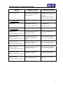
10.1 Alarm Codes and Troubleshooting ..................................................................................... 81
10.2 Service Monitors ................................................................................................................. 81
10.3 I/O Assignments ................................................................................................................. 81
Appendix
Common Terms and Definitions
List of Figures
4
EZT-560 User’s Manual
1. Overview
This manual has been tailored to cover all of the specific features and options available on the EZT560 environmental chamber controller. Note that all options and/or features may not be available for
your particular chamber. It is highly recommended that you read this manual thoroughly and
understand all aspects of the EZT-560’s operation prior to operating your chamber.
1.1
Safety Information
Note, caution and warning symbols that appear throughout this manual are to draw your attention to
important operational and safety information.
A “NOTE” marks a short message to alert you to an important detail.
A “CAUTION” safety alert appears with information that is important for protecting your equipment
and performance.
A “WARNING” safety alert appears with information that is important for protecting you, others and
equipment from damage. Pay very close attention to all warnings that apply to your chamber.
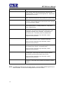
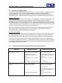
Device Under Test (DUT) Protection
The environmental chamber is equipped with high heat limits and/or safety devices. These devices
are installed to protect the chamber from exceeding design limits. These devices remove power from
the chamber’s heaters ONLY and DO NOT remove power from the device under test.
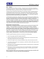
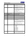
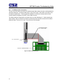
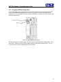
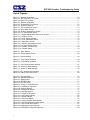
Provisions must be made by the end user to de-energize the tested device in the event of an overtemperature condition. For this reason, the chamber is equipped with a DUT safety relay that should
be connected to the device’s power supply control circuit at a minimum. This relay will open and deenergize the device under test to prevent a runaway thermal condition whenever the chamber is not
operating. See wiring example below:
120V~ (ac)
L1
L2
fuse
mechanical
contactor
DUT
safety
relay
120V/24V
transformer
coil
Figure 1-1 DUT Safety Connections
5
EZT-560 User’s Manual
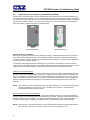
1.2
About the EZT-560
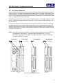
The EZT-560 Environmental Controller is a DCS (Distributed Control System) which uses different
hardware layers to perform the various functions needed to operate the chamber including user
interface, system monitoring and protection, as well as process control. This type of platform allows
for more flexibility in chamber design while providing a high level of reliability and control accuracy.
The heart of control is performed by individual Fuzzy PID controllers, one for each process. This
allows for the utmost in performance by providing a separate processor for each loop. The process
controllers utilize the latest technology with built-in adaptive tuning. This means that the process
controllers continuously monitor the operation of the chamber and adjust their control parameters to
achieve the most stable control possible without any user intervention. Adjusting PID parameters is a
thing of the past.
The chamber’s systems and components are monitored and controlled by the core CPU of the EZT to
insure that limits are not exceeded and profiles are executed precisely. The chamber is protected
from adverse operating conditions without the need for user intervention or knowledge on system
operation.
The user interface provides local operator control and monitoring of the system. It can track all user
actions with its built in security module as well as log process information and store it for later use.
Together, the system components form a complete SCADA (supervisory control and data acquisition)
system for total chamber management.
The graphic displays shown in this manual are representative of typical chambers. The screens may
vary slightly based on options present on your chamber.
6
EZT-560 User’s Manual
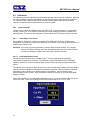
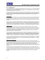
1.3
Touch Screen Interface
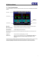
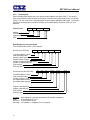
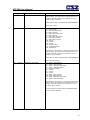
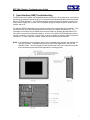
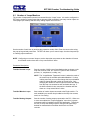
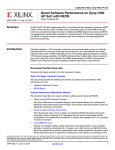
The EZT-560 display is divided into three main sections; the menu bar, main display area and detail
window.
Menu Bar
Main Display
Chamber
Light On/Off
Detail Window
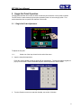
Print Screen
Figure 1-2 Touch Screen Interface
Menu Bar:
Used to navigate through the available monitoring and control screens.
Main Display Area:
Contains the active items for the menu item selected.
Detail Window:
Provides display specific information.
Note that there are two special control icons located at the lower right corner of the screen in the
detail window.
Light Icon:
Turns the interior chamber lighting on and off.
Printer Icon:
Prints the currently displayed screen to an HP 6540, 6940 or 6980 color
printer connected to the controller’s USB port (see Section 1.4 Print
Features).
To select items on the display, simply touch the desired text or numerical entry item. Do not use any
sharp or metal objects on the touch screen as they may damage the surface. For detailed
information regarding the different screen elements and their use, see the following sections.
7
EZT-560 User’s Manual
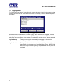
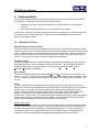
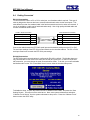
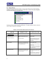
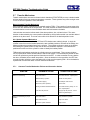
1.3.1 Menu Navigation
The EZT-560 display provides the user with an intuitive interface for navigating through the different
menus and settings without having to go multiple levels deep in screens like other “button style”
systems. The EZT-550 provides a “Windows” like feel with drop down menus and online help at all
times. This section of the manual provides an overview of the menu items and structure.
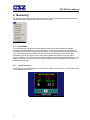
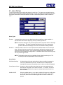
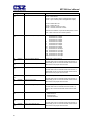
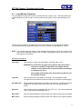
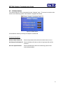
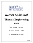
Main Menu (default on power-up)
Figure 1-3 Main Menu Navigation
View Menu
The “View” menu provides navigation to all standard view screens. These include loop view,
bargraph, trend, alarm monitor and alarm history operation screens.
Profiles Menu
The “Profile” menu provides access to the profile editing and monitor screens. From these screens a
user can open, save, edit, delete and run profiles.
Setup Menu
The “Setup” menu provides access to system and controller setup options.
Security Menu
The “Security” menu provides access for user logon as well as audit trail viewing if the security
system is enabled with users and the proper security rights.
Log Menu
The “Log” menu provides access to data log functions and the historical data viewer.
Help Menu
The help menu provides simple help regarding settings and use of screen parameters.
8
EZT-560 User’s Manual
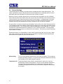
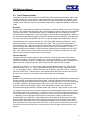
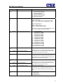
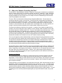
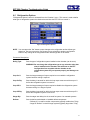
Profile Menu
Figure 1-4 Profile Menu Navigation
Views Menu
The “Views” menu provides navigation back to the main menu and the profile view screens. These
include profile status, profile entry, soak limits, autostart and plot profile screens.
Edit Menu
The “Edit” menu provides all of the functions needed to open, create, edit and save profiles.
Log Menu
The “Run” menu contains the profile control selections such as run, hold and stop.
Help Menu
The help menu provides simple help regarding settings and use of screen parameters.
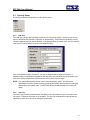
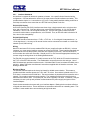
Setup Menu
Figure 1-5 Setup Menu Navigation
Views Menu
The “Views” menu provides navigation back to the main menu screen.
Setup Menu
The “Setup” menu provides access to the EZT-560’s setup screens and the link to the offline system
maintenance area.
Help Menu
The help menu provides simple help regarding settings and use of screen parameters.
9
EZT-560 User’s Manual
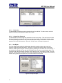
Logging Menu
Figure 1-6 Logging Menu Navigation
Views Menu
The “Views” menu provides navigation back to the main menu screen.
Edit Menu
The “Edit” menu provides access to the history files and the EZT-560 file utilities.
DataLogging Menu
The “Datalogging” menu provides access to the logging setup and historical file viewing utility.
Help Menu
The help menu provides simple help regarding settings and use of screen parameters.
System Maintenance Menu
Figure 1-7 System Maintenance Menu Navigation
Views Menu
The “Views” menu provides navigation back to the online setup screens.
Setup Menu
The “Setup” menu provides access to the service monitors and system settings.
Calibration Menu
The “Calibration” menu provides access to the input monitor calibration offset and analog output
calibration.
Help Menu
The help menu provides simple help regarding settings and use of screen parameters.
10
EZT-560 User’s Manual
1.4
Print Features
The EZT-560 interface will print a variety of graphic, trend and textual reports.
It can be connected to a standard “USB” inkjet printer (HP model 6540, 6940,
6980) via the standard USB host port provided on the chamber. No drivers
are necessary, operation is “plug and play”. Note that the USB port can be
used for “I-Stick” data backup and printing by “hot swapping” at any time
during the EZT-560’s operation.
The EZT-560 will alert the user to any problems during the print operation. After a print error (printer
not connected or bad cable), the EZT-560 will return to its normal operation after alerting the user.
The EZT-560 interface might change colors during printing to prolong ink cartridge life (blue
backgrounds require more ink than white backgrounds). The EZT-560 interface will be “locked” until
the print function is complete and then return to normal operation.
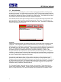
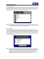
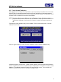
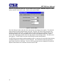
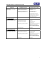
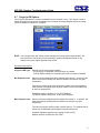
Important: When using the HP 6940 or 6980 DeskJet printers, the printer’s USB cable must be
plugged into the EZT-560 interface after the EZT-560 is powered up and in “normal” operating mode,
and the printer is powered up and ready for printing (neither device should be in startup mode).
When the USB cable is connected to the USB port, the following dialog will appear on the EZT-560
display (each time the printer cable is plugged in).
Figure 1-8 Print Driver Notification
Press the “X” at the top right of the dialog box and the dialog will disappear. The printer is now ready
for printing text or graphics from the EZT-560 interface. This dialog will not appear again unless the
printer cable is disconnected and then re-inserted into the EZT-560 “USB” interface connection.
The print driver in the EZT-560 interface provides standard “USB” printing using “PCL 3” language
support. Since printer models change so often, many manufacturers add features to new models of
printers. To take advantage of these new features (Ethernet connectivity, etc.), each manufacturer
supplies driver disks for different Windows “OS” versions. Since the EZT-560 is an embedded device
(no hard disk or moving parts), installation of these drivers is not required. The dialog box appears
due to the additional functionality the USB printer is transmitting to the EZT-560 interface. Pressing
the “X” at the top of the dialog instructs the EZT-560 interface to ignore the advanced printer features
and skip the installation of any print drivers that are not applicable to operation with the EZT-560.
11
EZT-560 User’s Manual
2. Monitoring
The chamber view screens provide various means of verifying chamber operation and performance.
The displays are accessed from the main menu under “View”.
2.1
Loop Views
The loop screens provide different viewing options for the control and monitoring of chamber
processes such as temperature, humidity, altitude, etc. The loop screens allow you to adjust the
current set points (SP) and view the process variables (PV) and percentages of output (%) for each
loop. The set points can be modified from these screens by touching the set point field. Upon
selecting a set point, the pop-up numeric entry pad will appear from which the set point can be
entered. However, if a profile is active, the set point fields are locked out from user adjustment. If the
loop is monitor only, the set point and percentage of output will not be displayed since no control is
associated with the input.
2.1.1 Single Loop View
The single loop view display shows one control loop or monitor input at a time. The auto-tune feature
is accessible from this screen.
Figure 2-1 Single Loop View
12
EZT-560 User’s Manual
2.1.2 Dual Loop View
The dual loop view display shows two control loops or monitor inputs at a time. It provides a large
standard display for control of both temperature and humidity, common on most environmental test
chambers.
Figure 2-2 Dual Loop View
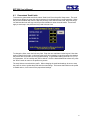
2.1.3 All Loops View
The all loops view display shows all available control and monitor inputs available on the chamber in
a tabular format. From this view all setpoints, process variables and output percentages can be
monitored at a glance.
Figure 2-3 All Loops View
The set point entry field is located at the lower right of this screen. In order to modify a loop’s set
point, select the loop by touching its tagname field in the table. The loop’s set point will then be
available for edit. Touch the edit field in order to enter the new set point.
13
EZT-560 User’s Manual
2.2
Graphing
There are two available graph formats for viewing each loop and monitor input of the EZT-560.
These include a process bargraph display and a time trend display. Each loop and monitor input has
its own bargraph and trend with individual display settings.
2.2.1 Loop Bargraphs
The bargraph display shows three individual bars representing the set point (SP), process variable
(PV) and percentage of output (%). If the loop is a monitor loop, the set point and percentage of
output will remain at the minimum range of the bargraph since no values are associated with these on
a monitor input. The range of the set point and process value bargraphs can be changed by
adjusting the “Lo” and “Hi” limits and pressing the “Set” button.
Figure 2-4 Loop Bargraph
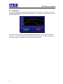
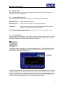
2.2.2 Loop Trends
The loop trend can display the set point (SP), process variable (PV) and percentage of output (%)
history over a period of time. The vertical axis determines the range of displayed data while the
horizontal axis determines the history period. The maximum time period that can be shown in the
trend is 4 hours.
Figure 2-5 Loop Trend
The trends on the EZT-560 have a unique drag-n-zoom feature. By using your finger to select an
area on the screen, the trend will zoom in on that area. To select a portion of the trend, touch and
hold the screen with your finger. Drag your finger across the trend and a box will be drawn around
the area. Removing your finger from the screen will cause the trend to redraw the trend with the
selected area. To return to the normal view, touch the “x” or “y” axis and select zoom normal.
14
EZT-560 User’s Manual
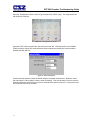
Trend Setup
To adjust the displayed variables, range and history period, touch the “Setup” button in the upper right
corner of the trend display. The Trend Setup screen will appear with the available adjustment
controls.
Figure 2-6 Trend Setup
Trend Zero
The zero value sets the minimum range of the vertical access for the trend variables.
Trend Span
The span value sets the maximum range of the vertical access for the trend variables.
Time(Mins)
The time interval is in minutes and adjusts the displayed time period for the trend. The allowable
range is from 4 to 240 minutes (4 hours).
Trend Points
To adjust what items are shown on the trend, select/deselect the desired items by touching the check
box next to the variable.
Press the “Done” or “Cancel” button to return to the trend screen. Any adjustments made when the
“Cancel” button is pressed will be disregarded. Each time a trend setup is changed, the trend will fill
with previous history and then operate in “real time” mode with the current settings.
15
EZT-560 User’s Manual
2.3
Alarm Monitor
The alarm monitor screen displays any current and/or previously silenced alarms according to time
and date of occurrence. On each new alarm occurrence, The EZT-560’s screen background will turn
red to notify the user of a new alarm. Once the alarm is silenced, the screen background will revert to
the standard blue background; however, the alarm may still be present. The chamber will not restart
until all alarms have been silenced and the alarm condition has cleared.
If the chamber does not restart upon silencing of the alarm, verify that all manual reset safeties have
been reset and the alarms have been cleared by pressing the “Clear” button. This will remove all
alarms from the list. If the alarm is still present, the alarm will not clear. See section 10, Diagnostics,
for alarm codes and corrective actions.
Figure 2-7 Alarm Monitor
Pumpdown
Chambers with large horsepower refrigeration systems have an automatic mode of operation called
“pumpdown”. The refrigeration system is in this mode whenever it is not running. In pumpdown
mode, the system 1 compressor will automatically turn on and off at preset pressures in order to force
the refrigerant into the high side of the system. This serves as a means to protect the compressor on
start-up. If pumpdown was not used, refrigerant could migrate throughout the system and
accumulate, typically in the coldest location like the compressor crankcase. On start-up, this
refrigerant could enter the compressor as a liquid and cause permanent damage to the compressor.
In addition, a crankcase heater is installed on the compressor and is energized when the compressor
is not running. This heats the oil in the crankcase of the compressor and boils out any refrigerant, so
that it can be pumped into the high side of the system.
If the chamber is equipped with the pumpdown mode of operation, the “Pumpdown” button will be
provided on the Alarm Monitor screen. This provides a manual way to reset pumpdown mode.
Pumpdown will be automatically disabled if main power is off for more than 30 minutes. This is due to
the fact that without main power, the crankcase heater will be off and can not warm the compressor.
Depending on the temperature of the compressor, this could allow refrigerant to accumulate in the
compressor causing a potentially damaging start-up.
The “Pumpdown Disabled” alarm will notify the operator of this condition. The chamber will not
operate when pumpdown is disabled. Pumpdown will automatically reset after the main power has
been on for a period of 4 hours or it can be immediately reset by pressing the “Pumpdown” button.
16
EZT-560 User’s Manual
2.4
Alarm History
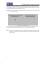
The alarm history screen provides easy access to historical alarm data. To access an alarm file,
press the “Open File” button on the upper right corner of the display. Select the desired alarm file
from the list and press “Open”. All alarms that occurred on that date will be displayed in the list box.
Figure 2-8 Alarm History
To clear the alarms from the list box, press the “Clear” button. Do this to refresh the display prior to
opening another alarm file. All alarm files are stored by day using the day’s date for the file name.
Thus, a new file will be created every day in order to store any alarms for that day. If no alarms
occurred on a given day, an alarm file will not be created for that day.
17
EZT-560 User’s Manual
2.5
System Status Monitor
The system status monitor provides non-critical alarm information or alerts to indicate specific
operational conditions or limits that have been reached in the chamber’s operation.
Figure 2-9 System Status Monitor
Non-critical alarms and alerts that require operator attention will be indicated by an intermittent
beeping of the chamber’s audible alarm. This alert can be silenced through the use of the “Silence”
button. See section 10, Diagnostics, for alarm codes and corrective actions.
18
EZT-560 User’s Manual
3. Single Set Point Operation
The EZT-560 controller can function as either a static set point controller or as a profile controller.
The EZT-560 is in static mode (single set point operation) when it is not running a profile. This
section describes how to operate the chamber in this mode.
3.1
Single Set Point Adjustment
Figure 3-1 Single Set Point Adjustment
To adjust the set point:
1.1.1.
Select one of the loop views from the main View menu.
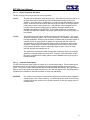
2. Input the set point temperature.
Press the numeric display for the set point (SP) for temperature. The set point adjust keypad will
pop up on the screen. Enter the desired set point value and press the “Done” button.
Figure 3-2 Numeric Entry
3. Turn the Chamber event on to start the chamber, see section 3.2 below.
19
EZT-560 User’s Manual
3.2
Manual Event Control (Chamber On/Off)
Events are the “switches” used to turn the chamber, its related functions and optional systems on and
off. These events can be manually turned on and off as well as programmed into profiles so that they
can be turned on and off at set time intervals.
Figure 3-3 Manual Event Control
To turn the chamber and optional events on/off:
1. Select the “Manual Event Control” from the main View menu.
2. Select the events you wish to turn on by checking the check box next to each event in the list box.
To turn off events, de-select the check box next to the event.
3. Press the Update button to set the new event status. Note that the events will not turn on or off
until the update button is pressed.
3.2.1 Standard Chamber Options
The first event is the “switch” that turns the chamber on and off. This will enable air circulators,
pumps, heating/cooling systems and any other components associated with the operation of the
chamber. This event is present on all chambers. Depending on the options provided with your
chamber, additional events may also be present.
3.2.1.1 Humidity
The humidity event turns the chamber’s humidity system components on and off. Note that when
humidity is turned off, the relative humidity is still measured and displayed; however, no control takes
place to obtain the target set point. The humidity system will not operate unless the chamber event is
also turned on.
NOTES on humidity system operation
Temperature Extremes
When operating your environmental chamber at extreme air temperature set points, below freezing
(0°C / 32°F) or above boiling (100°C / 212°F), the chamber is not capable of controlling humidity.
This is due to the physical properties of air and its ability to hold moisture at standard atmospheric
pressures when at these temperatures.
20
EZT-560 User’s Manual
To prevent malfunction or damage to the chamber, the EZT-560 control system automatically
disables the humidity system components when outside of the valid operating temperature range.
The event will remain on; however, so once the air temperature within the chamber returns to valid
operating temperatures, humidity control will resume at the target set point.
When humidity is disabled due to the chamber air temperature, the corresponding System Status
Monitor indicator will illuminate to indicate that this condition is present.
Minimum Humidity Limitations
The standard humidity option provides a lower limit of humidity control relating to a 4.4°C (40°F)
dewpoint. The dewpoint refers to the temperature at which the air contains the maximum amount of
moisture it can hold. When a surface drops to that temperature or below, condensation will occur on
that surface. The dewpoint varies logarithmically with temperature and relative humidity. This means
that at higher temperatures, a much lower humidity level can be obtained because the air can hold
more moisture the warmer it becomes.
For example, an air temperature of 85°C (185°F) and relative humidity of 12%, is the equivalent
dewpoint of air at a temperature of 5°C (41°F) and 79%. Both of these values are at the minimum
achievable dewpoint of the chamber, and thus the minimum achievable humidity at the related
temperature. If you were to set the humidity set point at 0% for example, the humidity level would
never reach 0 since the chamber is not capable of removing any more moisture from the air.
The EZT-560 is programmed to determine what the minimum achievable humidity point is at any
given temperature and will control to that limit. Therefore, the system will not overwork itself trying to
reach an unattainable point. This prolongs system life and reduces wear and tear on humidity system
components. Thus, if you set a set point of 0%, you can be confident that the environment within the
chamber will remain as dry as possible at any given temperature within the operating range.
When humidity is limited due to the fact that the minimum dewpoint has been achieved, the
corresponding System Status Monitor indicator will illuminate to indicate that this condition is present.
If your chamber is not obtaining the desired humidity level, check the status monitor to verify that you
are not trying to operate the chamber at a point outside of the chamber’s minimum dewpoint
capability.
Maximum Humidity Limitations
Certain chambers have limitations on the maximum humidity level that they can operate at a given
temperature in order to protect the chamber structure. This limit typically applies to modular
chambers. These chambers are constructed of individual panels that lock together to form the
chamber. The panels have an inner chamber liner and outer skin with a foam insulation sandwiched
between them. They are primarily used for large walk-in/drive-in chambers. Due to the materials
used in the construction of the modular panels, the humidity is limited to a maximum 70°C dewpoint
which corresponds to a maximum of 95% at 70°C (158°F).
When humidity is limited due to the fact that the maximum dewpoint has been achieved, the
corresponding System Status Monitor indicator will illuminate to indicate that this condition is present.
If your chamber is not obtaining the desired humidity level, check the status monitor to verify that you
are not trying to operate the chamber at a point outside of the chamber’s maximum dewpoint
capability.
21
EZT-560 User’s Manual
3.2.1.2 Altitude
The altitude event turns the chamber’s altitude system components on and off. Altitude chambers are
specifically built to withstand atmospheric pressures. They have heavy gauge liners with additional
internal structure for reinforcement. They simulate altitude by utilizing a vacuum pump to draw air out
of the chamber. The EZT-560 converts the resultant pressure within the chamber into feet, thus
altitude can be entered directly in feet. The altitude system can operate independently of the
chamber conditioning system.
NOTES on altitude system operation
Chamber Temperature Control Limitations
As altitude increases, the air density within the chamber decreases. The heating and cooling
systems require a minimum amount of air flow in order to operate correctly and control the internal
chamber air temperature. The altitude system will inhibit the operation of the heating and cooling
systems when the altitude increases beyond the design limits. This limit is typically around 60Kft.
Humidity Control Limitations
On most altitude chambers with the humidity system option, operation of the humidity system is
inhibited when the altitude system is enabled. The vacuum system used to control the internal
chamber pressure, can not operate with the addition of moisture. Only altitude chambers with
vacuum systems specifically designed to operate with the presence of moisture will allow humidity
control with the altitude system enabled.
3.2.1.3 Auxiliary Cooling
The auxiliary cooling system utilizes LN2 or CO2 as a boost cooling medium to assist the refrigeration
system in lowering the chamber air temperature. It is an inexpensive method for fast cooling
transitions without having to make the investment in a high horsepower refrigeration system that may
rarely be used. It can also be used as the primary cooling source for ultra low temperature operation
on chambers designed to operate at temperatures below -84°C (-120°F)
When this option is installed on the chamber, turn the “Aux Cooling” event on. When the boost is
required during a pull down, the EZT-560 will turn on the boost cooling solenoids and inject LN2 or
CO2, into the chamber to drop the temperature as required. Once the set point is achieved, the boost
solenoids will close in order to conserve LN2 or CO2 since it is no longer required, and allow the
refrigeration system to maintain the temperature.
If your chamber is designed for ultra low temperature operation, and the set point is below the
minimum achievable temperature for the refrigeration system, the EZT-560 will disable the
refrigeration system and use the boost cooling system for the primary cooling source. This
automatically protects the refrigeration system from damage and optimizes system operation.
22
EZT-560 User’s Manual
3.2.1.4 Dry Air Purge/Low RH Option
The dry air purge event can provide two levels of operation.
Level 1 -
The first level of this option is dry air purge only. The purge only option consists of an
air dryer which dries a small volume of air and discharges the dry air within the
chamber. This helps reduce condensation on surfaces within the chamber by drying
the air. When this event is turned on with the purge only option, the air dryer will run
continuously until the event is turned off. If the chamber is also equipped with the
humidity option and the humidity system is enabled, the purge system will be
disabled automatically by the EZT-560. The humidity system can not control the
humidity level within the chamber if the purge system is continuously trying to dry out
the chamber.
Level 2 -
The second level of this option includes the frozen coil (low RH) option. This option
allows the chamber to reach a –29°C (-20°F) dewpoint. This relates to lower relative
humidity capabilities. When the low RH option is installed and the humidity system is
enabled, the dry air purge system is operated in conjunction with the frozen coil
automatically by the EZT-560 controller based on the air temperature and humidity
set points. When required to obtain low humidity levels, the frozen coil and dry air
purge systems will start in order to achieve the target set point. When no longer
required, they will automatically turn off.
This option also provides the benefit of being able to manually use the dry air purge
system by turning the purge event on and off. However, in the case where the low
RH option is installed, the humidity system must be disabled for the dry air purge to
function manually.
3.2.1.5 Customer Event Option
The EZT-560 controller has the ability to control up to 15 event output relays. These outputs can be
manually turned on and off, and they can also be controlled programmatically through a running
profile. They can be used to start and stop devices under test within the chamber, turn signal beacon
lights on and off to indicate steps within the test cycle, etc. With this option, a pair of binding posts is
provided on the chamber for external connection to each relay individually.
CAUTION
The customer event output connections are rated for 24V AC/DC and are capable of
switching up to 6A of current (resistive). To switch high power loads, the event relay
must be used as the “switch” to turn a power contactor on and off to supply power to
the load device.
23
EZT-560 User’s Manual
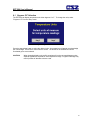
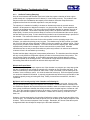
3.3
One-Touch Tuning
All of the EZT-560 control loops feature the one-touch tune. No more tuning parameters to adjust or
settings to change. The EZT-560 loop controls utilize fuzzy logic to continuously adapt to the process
in order to maintain it as close as possible to the set point. The controls merely need base-line
knowledge on the performance of the chamber and test load. To obtain this performance knowledge,
the controller can be tuned using the one-touch tune.
All Cincinnati Sub-Zero chambers are factory tuned; however, the chambers are typically empty and
under no load. Unless specific performance tests were performed at the factory for your particular
needs, the base-line performance may not be accurate once your product is placed inside the
chamber.
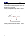
The one-touch tune makes it easy to tune the chamber to your product and performance needs. Just
run the chamber at ambient conditions and press the “AT” button on the single loop display screen for
the process to be tuned. The “AT” button will remain green for the duration of the tune to indicate it is
working. Once complete, you are ready to test product.
Figure 3-4 Tune Control Response
As you change product configurations or other loads within the chamber, you can re-tune to the new
configuration. All subsequent tests with that configuration will perform optimally. It is recommended
that only one loop be tuned at a time so that they do not interfere with the tune of the other loop.
24
EZT-560 User’s Manual
4. Profile Operation
A profile is a set of instructions programmed as a sequence of steps. The EZT-560 handles the
profile steps automatically, in sequence. The EZT-560 can store hundreds and even thousands of
profiles with up to 99 steps in each profile. This section covers the use and operation of the EZT-560
profiler. To access profile utilities, select “Profile Entry” from Profiles menu.
25
EZT-560 User’s Manual
4.1
Profile Entry
Profiles are created and edited from the Profile Entry screen. The following instructions describe the
steps involved for programming profiles.
1. To create a profile, go to the Profile Entry screen.
2. From the Edit menu, select “New Profile” and select “Yes” to create a new profile.
3. Enter the number of steps for the profile you want to create. Note that the number of steps can
be changed at any time during the profile entry to shorten or lengthen the profile as required.
Profiles can be from 1 to 99 steps in length.
4. For each step, enter the events, set points and time duration of the step.
5. Save the profile.
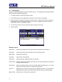
Figure 4-1 Profile Entry
Edit Menu Options
New Profile:
Clears any existing profile entry data so that a new profile can be entered.
Insert Step:
Inserts a step into the current profile at the current step number.
Delete Step:
Deletes the current step.
Copy Step:
Copies the current step data.
Paste Step:
Pastes previously copied step data to current step.
Select Profile:
Opens the file explorer window so that the user can select a profile from the profiles
currently stored in memory.
Save Profile:
Saves any changes made to the current profile under the existing name. If no name
exists, the user must enter one in order to save the profile.
Save As..:
Allows the user to save the current profile to a different file name. This is useful for
making different versions of the same profile that only requires minimal changes.
Delete Profile: Allows the user to delete the current profile.
26
EZT-560 User’s Manual
4.1.1 Step Events
For each step of the profile, you must input which events are to be on during the step. To enter the
step events, press the “Step Events” button. This opens the step event entry window. From this
window, select the events that are to be on during the step. Once the selections are complete, return
to the profile entry screen by pressing the “Back to Step Data” button.
Figure 4-2 Profile Step Events
NOTE: This must be done for each step individually. Also, for the chamber to operate, the relevant
chamber systems must be turned on via the event entry window. Even though a profile may
be in operation, if the events are not set, the chamber will not run.
4.1.2 GS Events
The GS Events are used to turn on the guaranteed soak option for one or more of the controlled
loops. In order to enable a guaranteed soak in a step, you must select the loop(s) to be monitored by
turning on the corresponding event. To enter the GS events, press the “GS Events” button. This
opens the guaranteed soak event entry window. From this window, select the events that are to be
on during the step. Once the selections are complete, return to the profile entry screen by pressing
the “Back to Step Data” button.
Figure 4-3 Profile Guaranteed Soak Events
NOTE: It is not recommended to use guaranteed soak events for ramping steps. The ramp rate
could be affected if the process variable deviates from the soak band because the profile will
be placed in hold. When the profile is in hold, the step length will be extended and the set
points will no longer ramp at the set rate. If the desire is to insure that the chamber is at
temperature, for example, prior to beginning a soak, use the “wait for” feature. To set the
guaranteed soak band for each loop of the profile, see section 4.2 Soak Limits.
27
EZT-560 User’s Manual
4.1.3 Wait For
The wait for function is a powerful tool for pausing a profile until a particular process variable reaches
a predefined state. This differs from the guaranteed soak function by being a single shot monitor.
With the guaranteed soak, the process variable is monitored throughout the whole step. If the
process exceeds the upper or lower deviation, the profile will hold until the process returns to within
those limits. The wait for function when enabled, puts the profile in hold and “waits for” the process to
achieve a particular value that you can set for the step. Once the process reaches this set point
value, the profile will resume.
To enable a wait for in a step, press the “Wait For” button. This opens the wait for entry window.
From this window, select the input to wait for and then enter the set point for the wait. Once the
entries have been made, return to the profile entry screen by pressing the “Back to Step Data” button.
Figure 4-4 Profile Wait For Input
NOTE: The set point entry for a “wait for” is critical for the “wait for” to operate correctly. During the
wait, the selected process input must cross the set point in order for the profile to resume
operation. If the selected input does not cross the set point value, the profile will remain in
hold on the step indefinitely.
4.1.4 Set Point/Step Time
To enter the set point(s) and time for a step, touch the set point/time display table at the bottom of the
profile entry screen. This opens the set point and time entry window. From this window, enter in the
time duration of the step in hours, minutes and seconds as well as the required set point(s) for the
step. Once the entries have been made, return to the profile entry screen by pressing the “Done”
button.
Figure 4-5 Profile Set Point Entry
28
EZT-560 User’s Manual
Entering a Soak Step
The set point entry for a step defines the target set point, i.e., the set point that will be achieved by the
end of the step. Thus, if the set point of a step matches the previous step’s set point, the chamber
will soak, remain at that set point, for the entire step.
Entering a Ramp Step
A ramp step is merely a step with a set point that is different from the previous step. The chamber
will ramp from the previous set point, to the set point of the current step linearly over the current
step’s time. This generates a ramp to the current set point.
Determining Ramp Rate
In order to enter a ramp rate, you must calculate the time it will take to go from the previous set point
to the new target set point. For example, if you desire a ramp rate of 5 degrees per hour from the
previous step’s 20 degree set point to the new 85 degree set point, the step time will be the difference
in temperature of 65 degrees divided by the rate of 5 degrees per hour. This equates to a time period
of 13 hours. Thus, the new step will have a set point of 85 degrees with a step time of 13 hours.
NOTE: A step time of zero can be entered for a step to implement an immediate set point change.
This will cause the chamber to ramp to a set point as quickly as possible. Used in
conjunction with a wait for on the following step, maximum ramp rates can be achieved that
are directly followed by a soak step at the same temperature.
4.1.5 Jump
The jump allows the profile to “jump” between different steps within itself. This is useful for repeating
the same ramp/soak combination during extended cycle testing of product. To enter a jump, enter
the step number to jump to and the number of jumps to be made. A jump count of zero on a step
indicates that no jump will be made regardless of what the jump step number is set to.
Jump Step:
This defines the step number that the profile will jump to at the completion of the
step.
Jump Count:
This defines the number of jumps that will be made from the step. Once all jumps
have been made, the profile will continue on to the next step in sequential order.
NOTE: The jump count defines how many jumps will be made. Thus, if you wish to perform 10
cycles within a profile, your jump count will be set to 9, 10 minus the 1 you performed prior to
reaching the jump step.
29
EZT-560 User’s Manual
4.2
Autostart
Autostart pauses a profile until the specified date or day, and time (of a 24-hour-clock). The autostart
settings are stored with the profile. To enter the desired start date or day, select “Auto Start Profile”
from the profile Views menu. Choose the desired autostart method, date or day, and enter the start
time settings. Once the desired entries have been made, press the “Done” button to return to the
profile entry screen.
Figure 4-6 Profile AutoStart
Autostart by Date: When this mode is selected, the exact date and time must be entered. Enter the
month, day, year and time of day in hours and minutes for when the profile is to
start. The day of week entry is not used so its value is irrelevant.
Autostart by Day:
When this mode is selected, only the day of week and time is required to be
entered. The date settings are ignored so the values are irrelevant.
NOTE: The time is entered in 24 hour (military) time format. To convert time from AM/PM format into
24 hour format, add 12 to the hours in PM time. For example, 2pm will be a value of 14 for
hours. A time of 5:30pm will be 17 hours, 30 minutes.
The autostart settings are stored with the profile; however, autostart can be used as a one
time setting. Select a profile that you wish to autostart at a particular time, make the desired
autostart selections and run the profile. The original profile settings will not be affected
unless you save the profile.
30
EZT-560 User’s Manual
4.3
Guaranteed Soak Limits
To access the guaranteed soak limits, select “Soak Limits” from the profile Views menu. The soak
limits screen allows you to set the control tolerance for soak steps when in profile operation. When
the process variables differ from the step set points by more than the soak limits, the profile will go
into hold and the timer will stop until the process variables re-enter the soak bands. These limits
apply to each step in the profile and only need to be set once.
Figure 4-7 Profile Guaranteed Soak Limits
To change the limits, touch the limit entry field. Enter the new soak band via the keypad. Note that
setting a band limit too tight, could prevent the profile from operating correctly because the chamber
may not be able to control to such a tight band setting. A typical band setting would be 1°C (1.8°F)
for temperature, 3% for humidity and 1Kft for altitude. Once the desired bands have been set, press
the “Done” button to return to the profile entry screen.
The soak limits are saved with the profile. When changing the soak band settings, be sure to save
the profile in order to update the profile with the new settings. This insures that each time the profile
is loaded and run, it will control to the proper band settings.
31
EZT-560 User’s Manual
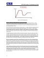
4.4
Plot Profile
The currently loaded profile can be viewed by using the Plot Profile utility. This allows you to see if
the profile you programmed matches the desired profile. To view the profile, select “Plot Profile” from
the profile Views menu.
Figure 4-8 Profile Plot
The EZT-560 will automatically generate a graphical representation of your profile and display it on
the screen. The Y-axis auto-scales to fit the set points within the profile. The X-axis auto-scales to
the number of steps in the profile. Note that jump steps are not shown.
32
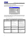
EZT-560 User’s Manual
4.5
Start/Stop Profile
To start a profile, it must first be loaded. The currently loaded profile is shown at the bottom of the
profile entry screen. To start the profile, select “Run” from the Run menu.
You will then be prompted to enter the step number for the profile to start on (default is step 1).
Figure 4-9 Profile Start
Use the scroll buttons to adjust the start step if required, and press the “Start Profile” button. The
profile will then be transferred into the profiler memory and started once the transfer is complete. The
“Profile Status” screen will automatically appear upon starting the profile so that the profile’s operation
can be observed.
NOTE: If the profile was set up with the autostart feature enabled, the profile will enter autostart
mode. Upon reaching the set date or day and time, the profile will begin running.
To stop a profile, there are two options. These selections are available from the “Run” menu.
Stop Profile:
Stops the running profile, but leaves the set points and events at their current
values when the profile stops. This allows you to stop a profile and continue its
operation in manual mode without shutting down the chamber and causing a
“hiccup” in control.
Stop Profile (all off): Stops the running profile and turns all events off. The set points will remain at
their current values when the profile stops; however, all chamber system stop.
This allows you to immediately stop a profile and all chamber operations.
33
EZT-560 User’s Manual
4.5.1 Hold/Resume a Profile
At any time during the operation of a profile, the profile can be manually put into hold. This stops the
profile timer; however, the chamber continues operation under the current step settings at the time
the profile was put into hold. To put a profile into hold, select “Hold Profile” from the Run menu and
select “Yes” to put the profile into hold.
To resume the profile at the point in which it was put into hold, select “Run Profile” from the Run
menu and select “Yes” to continue the profile. Upon a power failure, you can also resume a profile’s
operation in this manner from the point that power was lost depending upon the power recovery
action that is selected. See section 5.1 for more information regarding power recovery options.
4.5.2 Advance Previous/Next Step
The advance step function allows you to skip certain profile steps or repeat them by advancing to the
desired step. To advance to a previous or next step in the profile, the profile must be first put into
hold. Once the profile is in hold, the advance step menu items are enabled under the Run menu.
By selecting advance previous or advance next, the current step will be decremented or incremented
by 1 each time. When the current step number is on the desired step, place the profile back into run
and the profile will continue operation from the beginning of the selected step.
34
EZT-560 User’s Manual
4.6
Profile Status View
The profile status view provides all information regarding the operation of the current profile. It can be
accessed from the main Profiles menu as well as the profile Views menu.
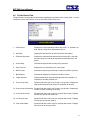
Figure 4-10 Profile Status View
1. Profile Status:
Displays the current operating mode of the profile, i.e., autostart, run,
hold, wait for, ramp, soak, guaranteed soak, etc.
2. Start Date:
Displays the date and time at which the profile was started.
3. Estimated Stop Date:
Displays the calculated stop date and time of the profile. Note that
this may vary due to wait for and guaranteed soak steps set in the
profile.
4. Current Step:
Indicates the step number currently being executed.
5. Step Time Left:
Displays the time remaining in the current step.
6. Wait for Input:
Indicates the input being monitored if a wait for condition is present.
7. Wait Setpoint:
Indicates the setpoint for the wait for condition if active.
8. Target Setpoints:
Displays setpoints for each controlled process of the chamber, i.e,
temperature, humidity, altitiude, etc.
9. Current Jump Step:
Dynamic field that is active only if step is a jump step. Displays the
step number that profile will jump to at completion of the step.
10. Current Jumps Remaining: Dynamic field that is active only if step is a jump step. Displays the
number of jumps remaining for the step.
11. Last Jump from Step:
Dynamic field that is active only if a jump has been made. Displays
the last step a jump was made from.
12. Last Jump to Step:
Dynamic field that is active only if a jump has been made. Displays
the last step a jump was made to.
13. Total Jumps Made:
Dynamic field that is active only if a jump has been made. Displays
the total count of all jumps made.
35
EZT-560 User’s Manual
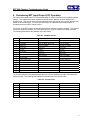
4.7
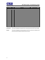
Profile Worksheet
The following table can be used as a template for creating profiles prior to entering them on the EZT560 controller. You can use this as a tool for quick checks to make sure all of your entries were made
correctly.
Profile Name:
Date Programmed:
Programmed By:
Step #
Set point
1
2
3
4
5
Step Time (H:M:S)
Chamber 1
Events
2
3
4
5
6
7
8
9-15
Customer 1
Events
2
3
4
5
6
7
8
9
10
12
12
13
14
15
GS
1
Events
2
3
4
5
Wait for
Wait for Set point
Jump Step
Jump Count
36
EZT-560 User’s Manual
5. Chamber Setup
This section covers the use of extended controller features that enhance the functionality of your
chamber. To gain access to the chamber setup options, select “Chamber Setup” from the Setup
menu.
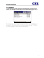
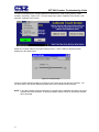
5.1
Power Recovery
The power recovery settings direct the EZT-560’s response to the interruption of electrical power.
The EZT-560’s battery-powered real-time clock tracks the amount of time the power is out. When
power is restored, the controller compares this amount of time to the Power-Out Time setting and
takes whatever action is selected in the Recovery State.
First, determine how long the power can be interrupted without adversely affecting results. Set the
Power-Out Time to this time. If power is returned in less time than this setting, the chamber will
resume operation where it left off. Note that profile run time stops while the power is off. If power is
returned after a time longer than this setting, the EZT-560 will take action based on the Recovery
State parameter:
Figure 5-1 Power Recovery
Hold
Select hold to have the chamber return to operation at the same point it was prior to
the power outage. If a profile was running, the profile will still be active; however, it
will remain in hold until manually set to continue.
Terminate
Select terminate to have the chamber default to the off state on power-up. If a profile
was active prior to the power outage, the profile will also be stopped.
Reset
Select reset to automatically restart the profile that was running at power failure. Use
this option if it is critical for a profile to run from start to finish without interruption.
Continue
Select continue to have the chamber pick-up where it left off on loss of power. If a
profile was running prior to the power outage, it will resume where it left off and
continue through the rest of the profile.
37
EZT-560 User’s Manual
5.2
Set Point Limits
The set point limits screen allows the user to adjust the minimum and maximum operating set points
allowed for the control loops. These limits can be used to prevent operators from entering a value
that exceeds the survivability limits of a product being tested.
Figure 5-2 Set Point Limits
WARNING The set point limits are factory set for the maximum safe operating range of the chamber.
These limits are locked out from user adjustment by default at the factory. User
adjustment of these limits, which exceed those limits set by the factory, may result in
damage to system components and will void the chamber warranty.
38
EZT-560 User’s Manual
5.3
Event Tagnames
The names of the optional customer events can be changed to describe what function you have
chosen for them to perform. To alter event names, select “Event Tagnames” from the Setup menu.
Figure 5-3 Event Tagnames
To change the name of the event, select the event by touching its current tag name. The pop-up
keypad will appear allowing you to enter a new description. Once complete, select “Done” and the
new name will appear in the event tag name list box. Once all changes have been made, press the
“Accept” button to save the changes to memory.
39
EZT-560 User’s Manual
5.4
Process/Alarm Tagnames
The names of the optional monitor inputs and alarms can be changed to describe what function you
have chosen for them to perform and what they are monitoring. To alter tagnames, select
“Process/Alarm Tagnames” from the Setup menu.
Figure 5-4 Process/Alarm Tagnames
To change the name of the event, select the event by touching its current tag name. The pop-up
keypad will appear allowing you to enter a new description. Once complete, select “Done” and the
new name will appear in the event tag name list box. Once the change has been made, press the
“Set” button to save the changes to memory.
40
EZT-560 User’s Manual
5.5
Alarm Settings
The EZT-560 provides user configurable alarms for each input. The alarms are activated when the
process value or temperature leaves a defined range. A user can configure how and when an alarm
is triggered, what action it takes and whether it turns off automatically when the alarm condition is
over.
Figure 5-5 Alarm Settings
Alarm Types
Process:
A process alarm uses one or two absolute set points to define an alarm condition. A
process alarm can be set for high only, low only or both high and low.
NOTE: The alarm settings for the product loop are fixed as a process alarm for both high
and low alarm. The alarm set points should be set by the user to protect the
product under test from damage in the event of a thermal runaway condition.
Deviation: A deviation alarm uses one or two set points that are defined relative to the control set
point. High and low alarm set points are calculated by adding and/or subtracting offset
values from the control set point. If the set point changes, the window defined by the
alarm set points automatically changes with it. A deviation alarm can be set for high only,
low only or both high and low.
NOTE: The deviation alarm type is not available for the optional monitor inputs. The
monitor inputs are not associated to a control set point.
Alarm Modes
Self Clear/Latching:
A latched alarm will remain active after the alarm condition has passed. It
can only be deactivated by the user. An alarm that is not latched (selfclearing) will deactivate automatically when the alarm condition has passed.
Close/Open on Alarm: An open on alarm condition means that the event output assigned to the
alarm will be energized in a non-alarm condition, i.e., fail-safe. A close on
alarm settings means that the output is normally open and will close in an
alarm condition.
Audible On/Off:
When the audible alarm is on, an alarm condition will trigger the audible horn
on the chamber and it will sound until silenced by the user. If the audible
alarm is off, there will be no audible signal when an alarm condition is
present.
41
EZT-560 User’s Manual
Shutdown/Continue:
An alarm set to continue will not affect the operation of the chamber when in
alarm condition. If the alarm is set for the shutdown mode of operation, the
chamber will turn off all systems in an alarm condition
Output Assignment
If the customer event option is supplied on the chamber, the alarm can be assigned to one of the
events. Utilizing the “close on alarm” or “open on alarm” mode settings, the event output will turn on
and off with the alarm it is assigned to.
NOTE: When setting an event output as an alarm, the output can still function as an event. Thus, the
output will be on if the event output is on or if the alarm state and mode tells it to be on. More
than one alarm can also be tied to the same output. This allows one output to function as a
remote indicator for any configured alarm condition.
Alarm Set Points
High Set Point (Hi SP): The alarm high set point defines the process value or temperature that will
trigger a high side alarm. It must be higher than the alarm low set point.
Low Set Point (Lo SP): The alarm low set point defines the temperature that will trigger a low side
alarm. It must be lower than the alarm high set point.
Hysteresis (DB):
An alarm state is triggered when the process value reaches the alarm high or
alarm low set point. Alarm hysteresis defines how far the process must return
into the normal operating range before the alarm can be cleared.
It creates a zone inside each alarm set point. This zone is defined by adding
the hysteresis value to the alarm low set point or subtracting the hysteresis
value from the alarm high set point.
42
EZT-560 User’s Manual
5.6
Product Control
If the chamber is equipped with the product control option, this screen will be accessible from the
Chamber Setup menu.
Figure 5-6 Product Control
Product control is a control strategy in which one control loop provides the set point for another loop.
It allows the process or part temperature to be reached quickly while minimizing overshoot. Product
control can be used to optimize the performance of chambers containing product with long thermal
lag times.
If only single-loop control is used, i.e., air temperature, the air will reach its designated set point and
the chamber will hold at this temperature. However, the part in the chamber may take hours or even
days to reach the temperature you desire due to its thermal mass. As the part temperature
approaches the set point, the difference between the part temperature and the air temperature
decreases. This difference in temperature is what forces the heat to move between the part and the
air. The lower this difference, the slower the heat moves. The composition of the material, whether it
is a natural insulator or conductor, also affects this rate of heat transfer.
The product control feature can be used to speed up this process and insure that your part reaches
the set temperature. It does this by monitoring the part temperature through the product control loop,
and based on the set point for product temperature, generates a set point for the air temperature
control loop. This set point is then automatically fed into the air temperature control loop. This allows
the air to exceed the desired product temperature and increase the temperature difference between
the part and the air. This accelerates the transfer of heat between the air and product under test.
There are two modes of operation for the product control feature, deviation and process. These
modes define how the air temperature set point is calculated.
Deviation: This mode uses the lower and upper set points to generate a set point that is defined
relative to the product set point. The upper and lower range of the air temperature set
point is calculated by adding and/or subtracting these values as offsets from the product
set point. As the product set point changes, the window defined by the upper and lower
points automatically changes with it.
Process:
This mode uses the lower and upper set points as the upper and lower range of the air
temperature set point. The output of the product control loop is linearized between these
two values in order to provide the set point for the air temperature loop.
43
EZT-560 User’s Manual
The deviation mode has the benefit of limiting the maximum and minimum temperature that the air
can achieve relative to the desired product set point. This allows the system to be fine tuned to the
minimum amount of overshoot required to obtain the desired product temperature.
The process mode has the benefit of maximum change rates by allowing the air temperature to go to
absolute limits. This allows the product to achieve set point temperature as quickly as possible, but
does so at the cost of stability. If the part has a large thermal lag, the air temperature control may
oscillate uncontrollably once the product reaches set point because of the large overshoot. In most
cases, deviation control is the recommended choice.
44
EZT-560 User’s Manual
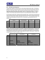
5.7
Condensation Control
The optional condensation control feature is for situations in which condensation is undesirable or
detrimental to the product being tested. When enabled, the rate of rise in temperature is limited in
order to allow the humidity control system to strip moisture from the chamber in order to keep the
dewpoint of the air below the product temperature. If the dewpoint of the air were to exceed the
product temperature, moisture could form on the product’s surface.
Figure 5-7 Condensation Control
There are many factors that can affect the performance of the chamber including product placement,
mass of product and air distribution throughout the chamber. The required ramp rate limit will be
affected by these factors. It may take a little trial-and-error to determine what setting is best for your
testing needs.
Ramp Rate Limit:
Adjustable ramp rate limit. Valid range is from zero to 5.0°C (9.0°F). Note
that a limit setting of zero will have no limiting affect on rate of rise.
Dewpoint:
Read only parameter which displays current dewpoint of the air within the
chamber.
DP Limit:
Read only parameter which displays the maximum dewpoint that can be
maintained without causing condensation on product.
Monitor Mode:
Defines the method of part temperature monitoring.
Single Input:
Low Input:
Hi Input:
Avg:
Uses single input, i.e., single sensor located on part.
Uses input with the lowest part temperature.
Uses input with highest part temperature.
Uses average of all selected part temperature inputs.
Input Selection:
Used to select which inputs will be used for monitoring part temperature.
Note that the standard system has only one selection, the product control
loop input. If the EZT-560 is equipped with the input monitor option, the
additional inputs will be listed for selection.
45
EZT-560 User’s Manual
5.8
Defrost Settings
These settings will be available on special systems equipped with the hot-gas defrost option. This
option is provided on systems that operate at ultra-low temperatures for extended periods of time to
periodically warm the refrigeration coils and remove the normal ice build-up.
Moisture in the air is naturally attracted to the cold surface of the refrigeration coils in the chamber.
This moisture freezes to the surface of the coil over time and can eventually cover the entire surface.
This will render the coil useless and block all airflow in the chamber. In chambers that run through
high and low temperature cycles, the moisture does not accumulate to a detrimental level, but in
chambers that run at low temperatures for days or weeks at a time, this can be a problem.
Hot-gas defrost is a means of warming the refrigeration coils to melt the ice, while minimizing the rise
in air temperature within the chamber. When defrost is enabled, the air circulators shut down and the
hot gas solenoid opens. The hot gas flows through the refrigeration coil and melts the ice. Once the
coil reaches a preset temperature limit, typically 10°C (50°F), defrost terminates. The refrigeration
system then prechills the coil prior to turning on the air circulators. This further prevents the warming
of the chamber’s contents.
Defrost can be set to run automatically or under manual control through the use of an event. When
auto mode is selected, the EZT-560 will monitor the conditions of operation and automatically start
defrost based on the parameters the user has entered.
Figure 5-8 Defrost Settings
Defrost Delay:
Time in minutes between defrosts when auto mode is enabled. This is based on
Individual operating conditions. It may take some analysis to determine how long
your chamber can run before defrost is required.
Temperature SP: Temperature below which defrost is enabled when in auto mode. After the
defrost delay, defrost will be activated. If at any time the chamber temperature
rises above the set point temperature, the delay timer will be reset and the
countdown will begin anew the next time the chamber temperature drops below
the set point.
46
EZT-560 User’s Manual
5.9
PC Comms/Web Server
This screen allows the user to set the slave address for the EZT-560 controller on the serial
communication link to a PC and view the IP address if connected to a network. It also provides
selections for enabling and disabling the Modbus slave (serial communications) and web server. For
more information regarding the use of the EZT-560 data communications, see section 9.
Figure 5-9 PC Comms/Web Server
47
EZT-560 User’s Manual
6. Security
The EZT-560 provides an enhanced array of security features. The security model provides an
administrator with the tools to add up to 30 users to the system. Each user must have a unique ID,
full name and password. Three levels of users are provided to include operator, supervisor and
administrator levels. Specific access rights can be assigned to each user level as well as password
aging for each user. Re-authentication is provided (if enabled) for any parameters that will change a
control parameter which could upset the process (i.e. setpoint, tuning, etc…). Re-authentication
requires that the logged in user must log in again before the process value will actually be changed.
This feature is provided for extra security. The following example will make re-authentication clearer:
A supervisor logs on the system. The supervisor then steps away from the system to take a phone
call but does not log out before leaving. If another user tries to change the control setpoint on any
loop the system will require another login (by an authorized user for that level) before the control
setpoint is actually changed. This provides an extra level of protection to make the system more
“tamper proof”.
NOTE: Default UserID is “FACTORY”.
Default Password is “CONTROL”
48
EZT-560 User’s Manual
6.1
Security Setup
All security parameters are accessed via the Security menu.
6.1.1 Add User
The “Add User” tab provides the ability to add up to 30 users to the system. Select the type of user
from the drop down list (Operator, Supervisor or Administrator). Press each field to add the user ID,
full name and password (no spaces allowed). If the passwords do not match or the user ID is already
used, the EZT-560 will alert the user and not accept the entry.
Figure 6-1 Security (Add User)
Click on the password aging checkbox if you wish to enable password aging for this user. If
password aging is enabled and the password has expired, a new password must be entered for the
user by the system administrator before that user can log into the system again.
NOTE: The system administrator can not use the “Password Aging” option. This will lock the
administrator out of the system, thereby preventing the system administrator from managing
passwords for the system users. The EZT-560 will prevent administrators from using this
option.
6.1.2 User List
The “Users” tab provides the administrator the ability to view information on each user entered into
the system. Password information is not available. The user can be deleted from this tab and the
password for each user can also be changed from this area.
49
EZT-560 User’s Manual
Figure 6-2 Security Users List
6.1.2.1 Delete User
The administrator can delete a user by selecting the user from the list. To select a user, touch the
UserID in the list box and press the “Delete User” button.
6.1.2.2 Change User Password
The administrator can also change the password of a user in the system. This may have to be done
if password aging is set up for the user or for other security reasons. To change a password, select
the user by touching the UserID in the list box and press the “Change Pswrd” button. Enter the new
password and confirm the password. Press the “Accept” button to change the password.
6.1.3 User Rights
The “User Rights” tab provides the administrator the ability to assign rights to each user level
(Operator, Supervisor and Administrator). Select the user type from the drop down box and then
enable or disable specific program functions (rights) by selecting the checkbox next to the function. If
the checkbox is selected, the user right will be enabled for the user level currently being edited. The
“Select All” and “Clear All” buttons will select or clear all rights in the “user rights” list view. You must
press the “Accept” button for each user level to save the selections for that user type, before selecting
another user type from the drop down list, or entries made will not be saved.
Figure 6-3 Security User Rights
50
EZT-560 User’s Manual
NOTE: You must have at least one user with administrator access and the “Access Security” right
option enabled in order to turn on security. There is no “back door” to the system. If the
password is lost or forgotten, you must contact Cincinnati Sub-Zero’s Service Department to
order a new compact flash card.
6.1.4 Security Options
The “Security Options” tab provides the administrator the ability to set the global security options.
Figure 6-4 Security Options
Enter Number Of Days Before Password Renewal Is Required
This is a global setting for all users. Password aging starts from the day the user is entered into the
system.
Re-authenticate User During Process Changes
This feature requires that the logged in user must log in again before the process value (at the
controller) will actually be changed.
Enable\Disable Audit Trail
This is a global setting that turns the audit trail on or off. When the audit trail is turned on, all operator
actions are written to a daily log.
Enable\Disable Security
This is the global setting that turns the EZT-560 security system on or off.
51
EZT-560 User’s Manual
6.2
User Log On/Off
When security is enabled, a user must log on to the system in order to gain access to privileged
items. To log on to the system, select “Log On” from the Security menu. Enter the user “UserID” and
“Password” on the login screen and press “Done” when finished. If the entries made are valid, the
user will be logged onto the system. In order for a user to log off the system, select “Log Off” from the
Security menu.
6.3
View Audit Trail
The “View Audit Trail” selection from the Security menu allows the user to view all audit trail files
stored in memory. This selection opens the audit trail viewer. Press the “Open Audit Trail” button to
open the explorer window. Select the desired audit trail file and press the “Open” button. The audit
trail files are stored by date. One file will be created for each day. If no activity occurred during a
given day, no file will be available.
6.4
Current User
The “Current User” selection merely provides a means of identifying the current user logged into the
system. If none of the users configured in the system are logged on, the current user will be
displayed as “CSZ System”.
52
EZT-560 User’s Manual
7. Logging
The EZT-560 logging features are accessed via the “Log” menu item. The system data logging
provides the ability to select individual points for logging, view datalog files and start/stop logging
operations. The logging ability of the EZT-560 provides an easy-to-use, convenient method to obtain
electronic data without the need for additional equipment.
7.1
Start/Stop Logging
The main system data logging screen is used to start or stop the logger and also to add a file prefix to
the file name. File names are automatically generated using m_d_y_h_m_s format (file prefix is
entered before the date/time stamp if the user enters one).
The main logging screen will display the current data file name if system logging is enabled as well as
the currently loaded file name (on the bottom status bar), if a historical file is loaded. To start the log,
press the “Logging On” button (controller variables must be assigned first by selecting the “Select
Points For Logging” menu item). Any time logging is enabled, the “Logging On” button will be green.
Figure 7-1 Start/Stop Datalogging
The logging rate is adjusted on this screen by changing the value for the “Days before new file is
started” parameter. Files can be 1 to 31 days long (before system starts a new file) with datalog rate
dependent on file selection length. The data log rate (in minutes) is the number of days selected for
file length. If 5 days is selected for file length, the datalogger will save to disk every 5 minutes.
53
EZT-560 User’s Manual
7.2
Logging Setup
The “Select Points for Logging” screen allows the user to select any point(s) from the system for data
logging. The “Select All” and “Clear All” buttons provide a quick way to select or deselect all points in
the system.
Figure 7-2 Logging Setup
Use the checkbox to enable/disable a point for logging. When selections are completed, press the
“Accept” key to write the point selection to memory. This is important so that the EZT-560 saves the
settings for power-up operation. New settings will not take effect until the “Accept” button is pressed.
Log On Startup:
The log on startup option automatically turns logging on whenever the
chamber is powered on.
Log On Profile Run:
The log on profile run option is a convenient method for gathering information
that pertains only to the operation of a profile. When selected, the EZT-560
will turn the logger on at the beginning of a profile and off once the profile is
completed.
54
EZT-560 User’s Manual
7.3
History Files
Historical files are stored on the internal compact flash memory of the EZT-560. All files can be
opened and viewed on a trend graph.
7.3.1 Open/Delete History Files
The data logging “Edit” menu provides three options for handling stored historical files.
.
Open History File:
Opens a history file for review.
Delete History File:
Allows the user to delete the currently loaded history file.
File Utilities:
Allows the user to copy files to an I-Stick from internal storage as well as
delete files. See section 7.4 for more information.
NOTE: The “Delete History File” function does not affect the currently running data file, only the
current history file loaded for review.
7.3.2 View History Plot
In order to view a historical data file, it must first be opened by selecting “Open History File” form the
data logging Edit menu. Once the file has been opened, the user has the ability to adjust the time
period to plot from the file as well as what points are to be plotted.
To plot the file, select “View History Plot” from the Datalogging menu. The EZT-560 will open up a
trend graph and plot the selected channels. When you are done viewing the file, press the “Done”
button to return to the main datalogging menu.
Cursor/Name
Toggle Button
Figure 7-3 History Plot
The plotted channels will be shown across the top of the graph in their associated colors. The history
plot provides the drag-n-zoom feature like the loop trends. To zoom in to a particular section, touch
the screen and drag your finger across the screen to make a window around the particular area of
interest. Once you remove your finger from the screen, the plot will zoom in to that particular section.
To return to the full plot, touch either the x or y axis and select “Zoom Normal”.
55
EZT-560 User’s Manual
The Cursor button enables a cursor that can be scrolled across the plot in order to display the value
of each variable at that particular time. When the cursor is enabled, the name for each variable will
become the actual value at the current cursor position. As the cursor is scrolled across the plot, the
value will change accordingly. Pressing the Cursor button again will turn off the cursor and restore
the variable names.
Figure 7-4 History Plot Cursor
7.3.2.1 History Plot Time Setup
Select “Hist View Time Setup” from the Datalogging menu. The history time setup allows the user to
select any time frame (zoom in/out) to view historical data. A historical data file must be loaded
(using the Edit\Open History File menu item) before data can be plotted. The History Plot Setup
screen displays the start and end time for the currently loaded file in hours and minutes. Use the
sliders to adjust the time span for historical viewing if desired.
Figure 7-5 History Plot Time Setup
56
EZT-560 User’s Manual
7.3.2.2 History Plot Channel Setup
Select “Hist View Channel Setup” from the Datalogging menu. The history plot channel setup allows
the user to plot up to 8 channels of data simultaneously. Any point from the data file can be selected
along with the color for each channel to be plotted.
Figure 7-6 History Plot Channel Setup
Use the drop down boxes to select a channel for the plot and then the color for the channel. Press
the “Add Point” button to add the point to the current list of historical plot channels. The “Clear All”
button will clear the list of all points so a new group can be added for plotting. The “Add All” button
will automatically fill the list with the first 8 channels, if available, and assign individual colors to each
channel.
7.3.3 View Averages Report
The “View Averages Report” provides a text report that displays the average value over time for each
channel selected in the “History Plot Channel Setup” screen. Averages are calculated for the period
of time selected in the “History Plot Time Setup” screen. The report supplies the average value for
each channel over time as well as the combined average for all channels selected. This is a useful
tool with the monitor option because it can be used for analyzing gradients within the chamber or
within the product under test.
To view the averages report, select “View Averages Report” from the Datalogging menu.
Figure 7-7 Averages Report
57
EZT-560 User’s Manual
7.4
File Utilities
The “File Utilities” screen allows the user to copy or erase files from the internal compact flash card.
Complete file directories for all EZT-560 file types can be copied to the USB “I-Stick” or erased from
the internal compact flash card. Complete status for file functions as well as progress bar status is
displayed for the operator during copy/erase operations.
A quick note regarding file storage. The files (log files, alarm history and audit files) need some
maintenance every now and then. After a period of time, storage devices fill up and files require
backup or file deletion when no longer needed. The “File Utilities” section of the EZT-560 provides
all the functionality required for maintaining the internal compact flash card. The internal compact
flash card should not be removed from the EZT-560 interface. Any change to compact flash directory
structure (moving or deleting files with a PC) will cause the EZT-560 interface to stop operating and a
new compact flash card will need to be ordered. Never move or delete the directories unless using
the internal EZT-560 file utilities.
To copy files to the USB I-Stick:
Check the checkbox next to “Copy To I-Stick”. Press the specific button that represents the file type
to copy (Profile, etc.). All files from directory will be copied with progress status displayed to user.
To erase files from internal compact flash:
Check the checkbox next to “Delete From Internal Storage”. Press the specific button that represents
the file type to erase (Profile, etc.). All files from directory will be erased with progress status
displayed to user.
To copy files to I-Stick and then erase files from internal compact flash:
Check “Delete From Internal Storage” and “Copy To I-Stick” checkboxes. Press the specific button
that represents the file type to copy/erase (Profile, etc.). All files from directory will be copied and
then erased with progress status displayed to user.
Figure 7-8 File Utilities
NOTE: Use only Cincinnati Sub-Zero “I-Stick” USB memory cards for copy file utilities. CSZ has
tested and validated the “I-Stick” for proper operation and performance. CSZ does not
guarantee or support the use of any other USB memory device.
58
EZT-560 User’s Manual
When files are being copied to the I-Stick storage device, a directory for each file type will be created
to store the copied files. The directory structure is as follows:
Profile files directory:
Alarm files directory:
Audit files directory:
Log files directory:
Profiles_mm_dd_yyyy-hh_mm_ss
AlarmFiles_mm_dd_yyyy-hh_mm_ss
AuditFiles_mm_dd_yyyy-hh_mm_ss
DataFiles_mm_dd_yyyy-hh_mm_ss
The reason for using the date and time as part of the directory name is to make sure the user can
track the date and time of the file transfer. If a user transfers a file type more than once in a single
day the files will be grouped logically by time.
The data files can be opened directly with Microsoft Excel or any program that opens a comma
separated file format. You can copy or empty the “DataFiles” directory by simply plugging in the USB
“I-Stick” in a PC’s USB host port. This device then becomes like any removable disk attached to the
computer and can be manipulated as once while plugged into the PC. The I-Stick requires no drivers
when using WindowsXP operating system. The CSZ Data Viewer program is a free Windows
accessory program that allows users to view, plot and print data files and is available from CSZ.
NOTE: Alarm and Audit files are also written in a “.csv” format and can be opened directly with excel
after the “I-Stick” is inserted into the PC (after files are copied from internal compact flash to
“I-Stick” memory device). No additional software is required to view alarm or audit files.
Once files are deleted from EZT-560 storage devices, they are gone and can not be retrieved. Once
again, do not edit, move or delete any other files from the internal compact flash card unless using
the EZT-560 “File Utilities”. The EZT-560 will not operate properly if you do so.
“WindowsXP” and “Excel” are trademarks of the Microsoft Corporation.
59
EZT-560 User’s Manual
8. System Maintenance
System maintenance options are available from the Chamber Setup menu. To access system
maintenance, select System Maintenance from the chamber setup menu.
NOTE: Prior to entering system maintenance, all automatic chamber operations must be stopped.
This includes data logging and profile operation.
Upon selecting system maintenance, an alert will tell the user that the chamber will be taken off line.
The user can select “No” to return to the chamber setup menu without shutting down any current
operations. If the user selects “Yes”, all operating systems of the chamber will stop.
60
EZT-560 User’s Manual
8.1
Degrees C/F Selection
The EZT-560 can display temperatures in either degrees C or F. To change the units, select
“Degrees C/F” from the Setup menu.
Figure 8-1 Degrees C/F Selection
Press the appropriate button to select the desired units. A message box will appear to acknowledge
the units change. Press OK to close make the switch. The button for the selected unit will be
illuminated green once selected.
CAUTION
When changing display units, profile set points will not be converted between units.
Separate profiles are required for each temperature range. Equipment damage may
result if profiles of alternate units are used.
61
EZT-560 User’s Manual
8.2
Service Monitors
The service monitors provide service interval alerts and life total service numbers for chamber
components and systems. The service intervals are set by CSZ at the optimum period for system
performance and reliability. When a component exceeds its service interval, a notification alarm can
be generated. This will alert notify the operator that service should be performed at the next available
down period.
Figure 8-2 Service Monitors
When a service interval is exceeded, an alert can be set to illuminate the corresponding indicator on
the System Status Monitor screen. An audible alert can also be turned on to get the operator’s
attention. In order to clear the service alert, the elapsed service counter must be cleared.
To clear the service interval count, you must select the count that has been exceeded by touching its
description on the Service Monitor screen. A pop-up window will ask if the count is to be cleared for
the item you selected. Select “Yes” to clear the count. Note that the Service Monitor screen must be
showing the “Elapsed” count.
The service monitor screen can be set to display the elapsed service interval or the life total for the
component based on the selection made in the Service Info Setup screen. The alert method can also
be disabled if this feature is not desired.
8.2.1 Service Monitor Setup
The service monitor display options as well as alert action can be adjusted from the Service Info
Setup screen.
Figure 8-3 Service Monitor Setup
62
EZT-560 User’s Manual
Elapsed Service or Totals:
Selects which count is to be displayed on the Service Monitor
screen.
Enable/Disable Service Alarm:
Selects the method of service notification or disables alerts
completely.
Service alerts are disabled by default. To make changes, place a check in the appropriate check box
and press the “Accept” button. For information regarding the service monitors and what they mean,
see section 10, Diagnostics.
63
EZT-560 User’s Manual
8.3
Set Date/Time
The date and time can be adjusted by selecting Set Date/Time from the maintenance setup menu.
The current date and time will be displayed in the field entry windows.
Figure 8-4 Set Date/Time
To make adjustments, touch the desired field entry box. The pop-up keypad will appear allowing a
new value to be entered. Once all corrections are made, press the “Set Time” button. A message
window will appear to acknowledge that the new date and time have been accepted. Press OK to
close the message window.
NOTE: The time is set in 24 hour (military time). The day of week must be set correctly in order for
the profile autostart by day to function correctly.
64
EZT-560 User’s Manual
8.4
Touch Screen Calibration
After extended use and many hours of operation, it may be necessary to recalibrate the touch screen
of the EZT-560. A typical sign that the screen may be out of adjustment, is inaccurate responses
when attempting to press buttons, check boxes or adjust fields on the display. The calibration utility is
provided in order to readjust the screen when this happens.
NOTE: Even after calibration, some fields may require finesse to operate. Check boxes require
precise presses even when the screen is in full calibration. Most response issues result from
“fat-fingering” the display. Use the tip of your finger or a stylus if necessary to operate the
unit.
To access the screen calibration utility, select “Calibrate Touch” from the Setup menu. Push the
“Calibrate Touch” button.
Figure 8-5 Touch Screen Calibration
From the “System Settings” window, touch the “Calibrate” button to start the calibration utility.
Figure 8-6 Touch Screen Settings
Crosshairs will appear on the screen. At each crosshair position, touch the screen and hold position
until the crosshairs move to the next calibration point. Repeat this for each position in order to set the
calibration. The calibration requires five points, the center and four corners. Once complete, the
calibration utility will exit and return to the System settings window.
65
EZT-560 User’s Manual
Use the scroll arrow button in the Systems settings window to scroll to the right until you see the
“Save” tab. Touch the Save tab and press the “Save Registry” button. This will store the calibration
parameters in memory. If the settings are not saved, the changes will be lost when power is cycled to
the unit. Press the “OK” button on the upper right corner of the System settings window to close the
window and return to System Maintenance.
Scroll Tabs
Figure 8-7 Save Registry
8.4.1 LCD Settings
The “System Settings” window also provides access to the contrast and backlight adjustment of the
EZT-560 touch screen. To access these settings, perform the procedure above to access system
settings; however, do not perform the calibrate touch procedure.
The backlight is set to never turn off by default. To adjust the backlight, select the “LCD Settings” tab
from the system settings window. Using the drop down menu and select the time period for which the
backlight should turn off after no activity.
Figure 8-8 LCD Settings
Proceed to the “Save Registry” tab to save any changes in order for them to be the default at the next
power-up. If the screen appears too bright or too dim based on your ambient lighting, you can adjust
the screen brightness by selecting the “Contrast” tab from the System Settings window.
66
EZT-560 User’s Manual
Figure 8-9 Contrast
Use the slider to adjust the screen contrast to achieve the best picture for your viewing. Remember
to save any changes in order for them to be the default at the next power-up.
67
EZT-560 User’s Manual
8.5
Calibration
The calibration menu provides access to the analog input and output ranges for calibration. Note that
the “Input Calibration” will only be available if the monitor input option is provided on the chamber.
The “Analog Output” calibration will only be available if analog outputs have been provided for
retransmit of signals to external devices such as a chart recorder.
8.5.1 Input Calibration
There are two methods for calibrating inputs to the EZT-560. The control inputs, i.e., temperature,
humidity, product, etc., must be done on through the individual 9300 PID control(s) located on the
electrical panel. The monitor input calibration, is done through the EZT-560 touch screen interface.
8.5.1.1 Calibrating Control Inputs
See Chapter 4, “Calibration”, of the Future Design, FDC-9300 Self-Tune Fuzzy / PID Process /
Temperature Controller User’s Manual provided with your chamber for procedures and instructions on
calibrating the control inputs.
CAUTION Do not alter any other parameters or settings within the 9300 controls. Any changes
made to CSZ factory settings may cause unpredictable operation of the chamber which
can result in damage to equipment and will void the chamber warranty.
8.5.1.2 Calibrating Monitor Inputs
The monitor option provides up to 8 separate type “T” thermocouple inputs for monitoring
temperatures throughout the chamber. The calibration range is fixed within the EZT-560 Eagle
hardware; however, the user can input an offset in order to adjust for sensor tolerances and lead
affects.
Through the use of a simple ice bath, all sensors can be corrected within a matter of minutes without
having to disconnect leads or have expensive calibration equipment. With the chamber at ambient
temperature, place a bucket of ice filled with water in the chamber. Place all monitor input
thermocouples into the ice bath. Allow the probes to soak for a minimum of 30 minutes BEFORE
entering an offset.
Select “Input Calibration” from the System Maintenance menu. Enter the number of the input in the
“Input Num” field. The current reading from the input will be shown in the “Cur PV” field.
Figure 8-10 Monitor Input Calibration
68
EZT-560 User’s Manual
The reading should be 0°C (32°F), i.e., the ice bath temperature. To “zero” the input, enter the offset
value in the “+- Offset” field and verify the reading. Be sure to press the “Accept” button to save the
new offset value before proceeding onto other inputs or exiting calibration or the offset value will be
lost. The total error for the monitor inputs is +3.5°C (6.3°F). The input types are fixed and cannot be
changed. If replacing sensors, be sure to replace with the same type.
8.5.2 Output Calibration
The EZT-560 can have up to 4 analog outputs which can be used to retransmit setpoints, process
variables or percentages of output from the installed control loops. These outputs are optional and
not included on all chambers.
CAUTION Some outputs may be provided for specific control functions depending upon the design
of your chamber. Do not alter these output settings unless you are sure that they are
used for monitoring purposes only. If you have any questions regarding the use of the
output, contact Cincinnati Sub-Zero’s customer service department for assistance.
The analog outputs can be configured to retransmit signals either in a 0-10V range or a 4-20mA
range. The minimum and maximum values of the output can be set to correspond to a specific value
of the retransmitted source. The output will retransmit this source linearly from the minimum to
maximum range. To configure an output, select “Output Calibration” from the System Maintenance
menu.
Figure 8-11 Output Calibration
To configure an output, first select the output number by entering the value in the “Retransmit Output
#” field. Upon entering the value, the outputs current configuration will be loaded and indicated by the
LED’s next to the selected type and source. The minimum and maximum values will be shown in the
“Out Min” and “Out Max” fields.
To make changes to the output’s configuration, place a check in the box next to the desired type and
source for the output. Enter the new minimum and maximum values for which the output is to
retransmit. Once all modifications have been made, press the “Accept” button to save the changes.
If you do not press the “Accept” button, all changes will be lost if you leave the screen or enter a new
analog output number.
NOTE: If you change the analog output type, i.e., change from voltage to current or vice versa,
power must be cycled to the EZT-560 controller in order for the output to switch modes.
69
EZT-560 User’s Manual
Output Specifications
Output Range
Load Impedance
Applicable Load
Total Error
70
Voltage Output
0-10Vdc
2K ohm minimum
resistive
+1% of full scale
Current Output
4-20mA
300 ohm maximum
EZT-560 User’s Manual
9. Communications
This section is targeted towards new users interested in using data communications with CSZ EZT560 controllers. The purpose of this section is to enable users to:
1. Understand the basics of data communications via standard definitions, interfaces and
protocols.
2. Set up and use a simple network of one or more EZT-560 controller(s).
In this section, numbers in the format 0x00 represent values in hexadecimal. Numbers in the format
0 represent values in decimal and finally, numbers in the format 00000000 represent values in
binary unless otherwise stated.
9.1
Definition of Terms
Machine-to-Machine Communication
In order for machines to communicate with each other, they need a code called a character format or
character set. They need rules called protocol to govern their conversation and prevent confusion and
errors. Computers need a connecting interface over which to communicate. They may use one pair
of wires to send information in one direction and another pair to send in the opposite direction (full
duplex). Or they may use one pair to send in both directions (half duplex).
Character Format
The code or character format for the EZT-560 data communication is shared by virtually everyone in
the electronics industry. This code defines a computer stream of 1’s and 0’s, that are created by
varying a voltage signal in a regular manner. This code is the American Standard Code for
Information Interchange, called ASCII.
Bits and Bytes
The word bit is simply the contraction of the words binary digit. A bit is the basic unit in ASCII. It is
either a “1” or a “0”. A byte is a string of eight bits that a computer treats as a single character. ASCII
can use a single byte to represent each letter of the alphabet, each digit and each punctuation mark
we use.
ASCII
The ASCII code defines 128 separate characters, one for each letter, digit and punctuation mark.
ASCII also includes control characters similar to those we find on computer keys, such as backspace,
shift and return. It also has nine communications control characters for identification, enquiry
(inquiry), start of text, end of text, end of transmission, acknowledge, negative acknowledge and
escape. The ASCII code is sometimes written in a base 16 number system that is called
hexadecimal or “hex” for short. The numbers 0 through 9 represents the first ten digits of this system,
and the letters A through F represents the final six digits. The 128 ASCII character codes with the
decimal, binary and hexadecimal equivalents are listed in the table below.
ASCII Control Codes
ASCII Control Codes are used to give instructions to the remote device and result in specific actions,
such as a line feed instruction on a printer. ASCII Control Codes, the first 33 ASCII characters (non
printable), are important for the operation of communicating equipment. They give instruction to
remote devices that result in specific actions such as a line feed on a printer. Holding down the
keyboard control key while pressing the appropriate keyboard key will send these values.
71
EZT-560 User’s Manual
ASCII Chart
72
Char
Code
Decimal
Binary
Hex
Char
Code
Decimal
Binary
Hex
NUL
SOH
STX
ETX
EOT
ENQ
ACK
BEL
BS
TAB
LF
VT
FF
CR
SO
SI
DLE
DC1
DC2
DC3
DC4
NAK
SYN
ETB
CAN
EM
SUB
ESC
FS
GS
RS
US
SP
!
"
#
$
%
&
‘
(
)
*
+
,
.
/
0
1
2
3
4
5
6
7
8
9
:
;
<
=
>
?
Ctrl @
Ctrl A
Ctrl B
Ctrl C
Ctrl D
Ctrl E
Ctrl F
Ctrl G
Ctrl H
Ctrl I
Ctrl J
Ctrl K
Ctrl L
Ctrl M
Ctrl N
Ctrl O
Ctrl P
Ctrl Q
Ctrl R
Ctrl S
Ctrl T
Ctrl U
Ctrl V
Ctrl W
Ctrl X
Ctrl Y
Ctrl Z
Ctrl [
Ctrl \
Ctrl ]
Ctrl ^
Ctrl _
SPACE
Shift 1
Shift ‘
Shift 3
Shift 4
Shift 5
Shift 7
‘
Shift 9
Shift 0
Shift 8
Shift =
,
.
/
0
1
2
3
4
5
6
7
8
9
Shift ;
;
Shift ,
=
Shift .
Shift /
0
1
2
3
4
5
6
7
8
9
10
11
12
13
14
15
16
17
18
19
20
21
22
23
24
25
26
27
28
29
30
31
32
33
34
35
36
37
38
39
40
41
42
43
44
45
46
47
48
49
50
51
52
53
54
55
56
57
58
59
60
61
62
63
00000000
00000001
00000010
00000011
00000100
00000101
00000110
00000111
00001000
00001001
00001010
00001011
00001100
00001101
00001110
00001111
00010000
00010001
00010010
00010011
00010100
00010101
00010110
00010111
00011000
00011001
00011010
00011011
00011100
00011101
00011110
00011111
00100000
00100001
00100010
00100011
00100100
00100101
00100110
00100111
00101000
00101001
00101010
00101011
00101100
00101101
00101110
00101111
00110000
00110001
00110010
00110011
00110100
00110101
00110110
00110111
00111000
00111001
00111010
00111011
00111100
00111101
00111110
00111111
00
01
02
03
04
05
06
07
08
09
0A
0B
0C
0D
0E
0F
10
11
12
13
14
15
16
17
18
19
1A
1B
1C
1D
1E
1F
20
21
22
23
24
25
26
27
28
29
2A
2B
2C
2D
2E
2F
30
31
32
33
34
35
36
37
38
39
3A
3B
3C
3D
3E
3F
@
A
B
C
D
E
F
G
H
I
J
K
L
M
N
O
P
Q
R
S
T
U
V
W
X
Y
Z
[
\
]
^
_
`
a
b
c
d
e
f
g
h
I
j
k
l
m
n
o
p
q
r
s
t
u
v
w
x
y
z
{
|
}
~
DEL
Shift 2
Shift A
Shift B
Shift C
Shift D
Shift E
Shift F
Shift G
Shift H
Shift I
Shift J
Shift K
Shift L
Shift M
Shift N
Shift O
Shift P
Shift Q
Shift R
Shift S
Shift T
Shift U
Shift V
Shift W
Shift X
Shift Y
Shift Z
[
\
]
Shift 6
Shift `
A
B
C
D
E
F
G
H
I
J
K
L
M
N
O
P
Q
R
S
T
U
V
W
X
Y
Z
Shift [
Shift \
Shift ]
Shift `
Delete
64
65
66
67
68
69
70
71
72
73
74
75
76
77
78
79
80
81
82
83
84
85
86
87
88
89
90
91
92
93
94
95
96
97
98
99
100
101
102
103
104
105
106
107
108
109
110
111
112
113
114
115
116
117
118
119
120
121
122
123
124
125
126
127
01000000
01000001
01000010
01000011
01000100
01000101
01000110
01000111
01001000
01001001
01001010
01001011
01001100
01001101
01001110
01001111
01010000
01010001
01010010
01010011
01010100
01010101
01010110
01010111
01011000
01011001
01011010
01011011
01011100
01011101
01011110
01011111
01100000
01100001
01100010
01100011
01100100
01100101
01100110
01100111
01101000
01101001
01101010
01101011
01101100
01101101
01101110
01101111
01110000
01110001
01110010
01110011
01110100
01110101
01110110
01110111
01111000
01111001
01111010
01111011
01111100
01111101
01111110
01111111
40
41
42
43
44
45
46
47
48
49
4A
4B
4C
4D
4E
4F
50
51
52
53
54
55
56
57
58
59
5A
5B
5C
5D
5E
5F
60
61
62
63
64
65
66
67
68
69
6A
6B
6C
6D
6E
6F
70
71
72
73
74
75
76
77
78
79
7A
7B
7C
7D
7E
7F
EZT-560 User’s Manual
9.2
Serial Communication
The primary interface CSZ has chosen for the EZT-560 employs serial communication, which is the
exchange of data in a one-bit-at-a-time, sequential manner on a single data line or channel. Serial
contrasts with parallel communication, which sends several bits of information simultaneously over
multiple lines or channels. Not only is serial data communication simpler than parallel, it is also less
costly.
Baud Rate
The baud unit is named after Jean Maurice Emile Baudot, who was an officer in the French Telegraph
Service. He is credited with devising the first uniform-length 5-bit code for characters of the alphabet
in the late 19th century. What baud really refers to is modulation rate or the number of times per
second that a line changes state. This is not always the same as bits per second (BPS). However, if
you connect two serial devices together using direct cables then baud and BPS are in fact the same.
Thus, if you are running at 9600 BPS, then the line is also changing states 9600 times per second.
Typical baud rates for computers are 300, 600, 1200, 2400, 4800, 9600 and 19200 baud. As the
baud rate increases, so does the transmission rate of data. Thus you get more information in a
shorter period of time. However, the faster the transmission rate, the more susceptible it is to error
due to the quality of the cable and sources of electrical “noise” in the environment. In order to
balance throughput with reliability, CSZ has chosen to use 9600 baud as the data rate for the EZT560. Thus a device used to communicate with the EZT-560 must have its serial port set for 9600
baud in order to for data communications to work properly.
Start and Stop Bits
The start bit informs the receiving device that a character is coming, and a stop bit tells it that a
character is complete. The start bit is always a 0. The stop bit is always a 1. The human speech
equivalent of these bits could be a clearing of the throat to get someone’s attention (start bit); and a
pause at the end of a phrase (stop bit). Both help the listener understand the message.
A stop bit has a value of 1 - or a mark state - and it can be detected correctly even if the previous
data bit also had a value of 1. This is accomplished by the stop bit's duration. Stop bits can be 1,
1.5, or 2 bit periods in length. CSZ has chosen to use the default – and most common – length of 1
period for the EZT-560. A device used to communicate with the EZT-560 must also have its serial
port set to use a stop bit of 1 in order for data communications to work properly.
Parity Bit
Besides the synchronization provided by the use of start and stop bits, an additional bit called a parity
bit may optionally be transmitted along with the data. A parity bit affords a small amount of error
checking, to help detect data corruption that might occur during transmission. You can choose either
even parity, odd parity, mark parity, space parity or none at all. When even or odd parity is being
used, the number of marks (logical 1 bits) in each data byte are counted, and a single bit is
transmitted following the data bits to indicate whether the number of 1 bits just sent is even or odd.
For example, when even parity is chosen, the parity bit is transmitted with a value of 0 if the number
of preceding marks is an even number. For the binary value of 0110 0011 the parity bit would be 0.
If even parity were in effect and the binary number 1101 0110 were sent, then the parity bit would be
1. Odd parity is just the opposite, and the parity bit is 0 when the number of mark bits in the
preceding word is an odd number. Mark parity means that the parity bit is always set to the mark
signal condition and likewise space parity always sends the parity bit in the space signal condition.
Since these two parity options serve no useful purpose whatsoever, they are almost never used.
CSZ has chosen to use even parity with the EZT-560. A device used to communicate with the EZT560 must also have its serial port set to use even parity in order for data communications to work
properly.
73
EZT-560 User’s Manual
9.2.1 Interface Standards
An interface is a means for electronic systems to interact. It’s a specific kind of electrical wiring
configuration. CSZ has selected to use two of the most common serial interfaces used today. This
provides both a simple 1 to 1 connection to a PC or PLC using readily available cabling as well as a
multi-drop connection where more than one EZT-560 can be placed on the line.
EIA-232 (Full Duplex)
An EIA-232 (formerly RS-232C) interface uses three wires: a single transmit wire; a single receive
wire; and a common line. Only two devices can use an EIA-232 interface. A -3 to -24 volt signal
indicates a 1 and a +3 to +24 volt signal indicates a 0. The EIA-232 signal is referenced to the
common line rather than to a separate wire, as in EIA-485. Thus, an EIA-232 cable is limited to 50
feet, due to noise susceptibility.
EIA-485 (Half Duplex)
An EIA-485 interface uses two wires: a T+/R+, a T-/R- line. A -5-volt signal is interpreted as a 1, a
+5-volt signal as a 0. As many as 32 remote devices can be connected to a master on a multi-drop
network up to 4,000 feet long.
Wiring
Most PCs and some PLCs have a standard EIA-232 port (usually referred to as RS-232). In these
instances, you must use an interface converter to connect to EIA-485. These interface standards are
required to have a multi-drop system (more than one controller on the bus). See the list below for
some vendors who sell these converters. Should your PC or PLC have the appropriate interface, just
connect using the wiring shown in the Getting Started section.
For EIA-485, the terminal marked “A” usually connects to the T-/R- while the “B” terminal connects to
the T+/R+ of the EZT-560 controller. The standards do not specify the wire size and type. Use of
AWG 24 twisted pair provides excellent results. If shielded cable is used, terminate the shield at one
end only. Always follow the manufacturer’s instructions supplied with the interface converter. See
Biasing of Buses next.
Biasing of Buses
The EIA-485 standard requires the bus to be biased for reliable communication. This means to
provide termination resistors across the T+/R+ and T-/R- wires. One resistor is placed at the PC or
PLC where it connects to the EIA-485 bus. The second resistor is placed at the last controller on the
network. Do not place resistors at each controller. The impedance of the wires used for the bus
determines the resistor value. For twisted pair, the value is typically 120 ohms. In addition, it may be
necessary to have a pull-up and pull-down resistor between the power supply and ground of the
interface adapter.
Check the documentation that came with your interface adapter. Biasing the bus reduces reflection
of signals sent down the bus. These reflections are sometimes referred to as a standing wave. This
condition is most notable when communicating at high baud rates.
74
EZT-560 User’s Manual
9.2.1.1 Interface Converters
The purpose of an interface converter is to allow two different buses to be connected together.
Interface converters are required when connecting an EIA-232 port to an EIA-485 bus. The EIA-485
bus is a half duplex bus. This means that it can only send or receive data at any given time. Some
interface converters on the market provide the ability to have full duplex with the EIA-485 bus. This is
accomplished by using two receivers and transmitters tied in tandem. This type of converter will not
work with the EZT-560 controller. Be sure that the model you purchase is designed for half duplex.
Another consideration when selecting an interface converter is how the converter handles switching
between transmit and receive. Typically it is accomplished via a handshake line from the PC or PLC.
When data flows into the converter from the PC, a handshake line is placed high. When data flows
out of the converter to the PC, the handshake line is placed low. In this way, the handshake line
controls the direction of information. Another method of achieving this is to use a built-in timer. The
converter switches to transmit when a character is sent to it from the PC. After a period of time when
the PC has not transmitted, the converter switches to a receive mode.
It is important that you understand how your converter accomplishes this task. You are required to
wire this feature or make settings on the converter to enable this function. The PC will not talk to the
controller correctly with out properly setting this. Your converter may also require settings through dip
switches, to set up communications parameters like baud rate, data bits, start bits, stop bits and
handshaking. The converter may also require a separate power supply. Some converters get their
power from the handshake lines of the PC. If you rely on this method, you will need to wire these
additional lines. In addition, your software must set these lines high. A more reliable method is to
use the external power supply. This is especially necessary when using a laptop computer. See the
documentation that comes with your converter for more detail.
Not all converters are equal in performance. If your chamber operates in a harsh, electrically noisy
environment, this can cause less robust converters to work intermittently or not at all. CSZ has only
tested the converters listed below; however, CSZ makes no claims as to the performance or
compatibility of these converters with your PC or PLC device. These converters are equipped with
automatic send data control circuits, driver control in the converter hardware, so you don’t have to
work with software at all. The circuit monitors data flow and enables the driver during transmission
and automatically disables it when no data is being sent. There is no need to rework software or
install new drivers.
B&B Electronics
707 Dayton Road
PO Box 1040
Ottawa, IL 61350
Phone 815-433-5100
http://www.bb-elec.com
Part # 485OI9TB for EIA-232 to EIA-85
Part # 485PS2 (external power supply – required if handshake lines unavailable for power)
RESmith
4311 Smith Drive
Hamilton, OH 45011
Phone 513-874-4796
http://www.RS485.com
Part # ASC24T-B9FPS for EIA-232 to EIA-485 (provided with adapter cables and power supply)
75
EZT-560 User’s Manual
9.2.2 Protocol
Protocol describes how to initiate an exchange. It also prevents two machines from attempting to
send data at the same time. There are a number of different data communications protocols, just as
there are different human cultural protocols that vary according to the situation.
The protocol portion of EZT-560 communications is very important, because it provides a quality of
communication that others often don’t have. Protocol-driven communications are more accurate,
because they are less prone to both operator and noise errors. Protocol maintains system integrity
by requiring a response to each message. It’s like registered mail — you know that your letter has
been received because the post office sends you a signed receipt.
In EZT-560 data communications, a dialog will continue successfully as long as the messages are in
the correct form and responses are returned to the protocol leader. If the operator enters an incorrect
message, or interference comes on to the data line, there will be no response. In that case the
master must retransmit the message or go to a recovery procedure. If an operator continues to enter
an incorrect message or interference continues on the data line, the system will halt until the problem
is resolved. CSZ has selected Modbus RTU as the protocol of choice. Modbus RTU enables a PC or
PLC to read and write directly to registers containing the EZT-560’s parameters. With it you could
read all 180 of the controller’s parameters with three read commands.
Modbus Remote Terminal Unit (RTU)
Gould Modicon, now called AEG Schneider, created this protocol for process control systems called
"Modbus". It has the advantage over other protocols of being extremely reliable in exchanging
information. This protocol works on the principle of packet exchanges. The packet contains the
address of the controller to receive the information, a command field that says what is to be done with
the information and several fields of data. Reading from these registers retrieves all information in
the controller. The last item sent in the packet is a field to ensure the data is received intact. This is
called a cyclic redundancy check-sum. See the example below for information on how to generate
this value. All information exchanged is in hex numbers. The EZT-560 only supports the binary
version of Modbus, referenced as RTU. The ASCII version is less efficient and is not supported.
The CRC (Cyclical Redundancy Checksum) is calculated by the following steps:
1. Load a 16-bit register (called CRC register) with 0xFFFF
2. Exclusive OR the first 8-bit byte of the command message with the low order byte of the 16-bit
CRC register, putting the result in the CRC register.
3. Shift the CRC register one bit to the right with MSB zero filling. Extract and examine the LSB.
4. If the LSB of the CRC register is zero, repeat step 3, else Exclusive OR the CRC register with the
polynomial value 0xA001.
5. Repeat steps 3 and 4 until eight shifts have been performed. When this is done, a complete 8-bit
byte will have been processed.
6. Repeat steps 2 through 5 for the next 8-bit byte of the command message. Continue doing this
until all bytes of the command message have been processed. The final contents of the CRC
register is the CRC value.
When transmitting the CRC value in the message, the upper and lower bytes of the CRC value
must be swapped, i.e. the lower order byte will be transmitted first.
76
EZT-560 User’s Manual
Cyclical Redundancy Checksum (CRC) Algorithm
unsigned int calc_crc(unsigned char *start_of_packet, unsigned char *end_of_packet)
{
unsigned int crc;
unsigned char bit_count;
unsigned char *char_ptr;
/* Start at the beginning of the packet */
char_ptr = start_of_packet;
/* Initialize CRC */
crc = 0xFFFF;
/* Loop through the entire packet */
do{
/* Exclusive-OR the byte with the CRC */
crc ^= (unsigned int)*char_ptr;
/* Loop through all 8 data bits */
bit_count = 0;
do{
/* If the LSB is 1, shift the CRC and XOR the polynomial mask with the CRC */
if(crc & 0x0001){
crc >>= 1;
crc ^= 0xA001;
}
/* If the LSB is 0, shift the CRC only */
else{
crc >>= 1;
}
} while(bit_count++ < 7);
} while(char_ptr++ < end_of_packet);
return(crc);
}
77
EZT-560 User’s Manual
9.2.3 Write your own Modbus Application
Listed below are a few of the more common software packages that claim to support the Modbus
protocol. CSZ does not recommend any one software package nor supports the implementation of
any software package not sold by CSZ. This list is provided as informational only. CSZ makes no
claims as to the performance or compatibility of any software package with your particular PC or PLC
hardware. Contact the software manufacturer for more information in applying their software.
LabView by National Instruments
6504 Bridge Point Parkway
Austin, TX 78730-5039
Phone 512-794-0100
http://www.natinst.com
OI-2000 by Software Horizons, Inc.
10 Tower Office Park
Suite 200
Woburn, MA 01801-2120
Phone 617-933-3747
http://www.shorizons.com
SpecView by SpecView, LLC
41 Canyon Green Court
San Ramon, CA 94583
Phone 510-275-0600
http://www.specview.com
Wonderware 2000 by Wonderware
Corp.
100 Technology Drive
Irvine, CA 92718
Phone 714-727-3200
http://www.wonderware.com
78
EZT-560 User’s Manual
If you already have a software application that uses Modbus, you can simply skip to EZT-560
parameter table in the Getting Started section for the information your program will need. The rest of
this section provides information for writing a software application that uses Modbus.
1. You need to code messages in eight-bit bytes, with event parity, one stop bit (8, even, 1).
2. Negative parameter values must be written in twos' complement format. Parameters are stored
in two-byte registers accessed with read and write commands to a relative address.
3. Messages are sent in packets that are delimited by a pause at least as long as the time it takes to
send 30 bits. To determine this time in seconds, divide 30 by the baud rate. In the case of EZT560 communications at 9600 baud, this calculates to a minimum period of 3ms.
4. Values containing decimal points such as process values and setpoints, have the decimal point
assumed, i.e., the data exchange can only be performed using whole numbers. Thus, the value
must be offset by a factor of 10 in order to exchange the data correctly. For example, a setpoint
of 42.4 degrees must be sent as a value of 424 in order for the EZT-560 to set correctly.
Likewise, a process value read from the EZT-560 with a value of 967 is actually 96.7 degrees.
Consult the parameter table for the proper format of each value.
5. When monitoring a process, try to keep the number of read and write commands to a minimum of
500ms between exchanges to a single controller. Continuously reading data at a faster rate
consumes an excess amount of the controller’s processor time and does not provided any
additional benefits in process monitoring.
Handling Communication Errors
Reading or writing from/to a register that does not exist or is currently disabled will typically respond
with an erroneous value or result in a time-out response, i.e., the EZT will not respond with a return
message. Messages with the wrong format, timing or CRC are also ignored. A response will not be
given to them. Only messages with the proper format, timing and CRC will be acknowledged. It is
the user’s responsibility to handle the error appropriately within their own software and determine
whether to resend the message or halt for operator intervention.
User Responsibility
Refrain from altering prompts that do not appear on the EZT-560’s front panel or are not included on
the specific model. Care must also be taken that the process can not cause damage to property or
injury to personnel if the wrong commands are sent due to operator error or equipment malfunction.
Be sure to use limit devices on any equipment placed inside the chamber that can generate heat to
prevent system runaway.
79
EZT-560 User’s Manual
9.2.4 Packet Syntax
Each message packet begins with a one-byte controller address, from 0x01 to 0xF7. The second
byte in the message packet identifies the message command: read (0x03); write (0x10); or loop back
(0x08). The next n bytes of the message packet contain register addresses and/or data. The last two
bytes in the message packet contain a two-byte Cyclical Redundancy Checksum (CRC) for error
detection.
Packet format:
nn
nn
nnnn…
nn nn
address
command
registers and/or data
CRC
Read Register(s) Command (0x03)
This command returns from 1 to 60 registers.
Packet sent to EZT-560:
nn
03
nn nn
nn
03
00 nn
nn nn
controller address (1 byte)
read command (0x03)
starting register high byte
starting register low byte
number of registers high byte (0x00)
number of registers low byte
CRC low byte
CRC high byte
Packet returned from EZT-560:
nn
nn nn … nn nn
nn nn
controller address (1 byte)
read command (0x03)
number of bytes (1 byte)
first register data low byte
first register data high byte
…
…
register n data high byte
register n data low byte
CRC low byte
CRC high byte
Example:
Sent:
Received:
Message:
80
Read register 61 (chamber temperature) of controller at address 1.
01 03 00 3D 00 01 15 C6
01 03 02 00 EC B9 C9
236 (0x00EC) – temperature is 23.6 degrees
EZT-560 User’s Manual
Example:
Sent:
Received:
Message:
Read registers 60 and 61 (chamber setpoint and temperature) of controller at address 1.
01 03 00 3C 00 02 04 07
01 03 04 01 90 01 48 FA 44
400 (0x0190) and 328 (0x0148) – setpoint is 40.0 and temperature is 32.8 degrees
Write Register Command (0x06)
This command writes a value to a single register.
Packet sent to EZT-560:
nn
06
nn nn
nn nn
nn nn
controller address (1 byte)
write command (0x06)
register high byte
register low byte
data high byte
data low byte
CRC low byte
CRC high byte
Packet returned from EZT-560:
nn
06
nn nn
nn nn
nn nn
controller address (1 byte)
write command (0x06)
register high byte
register low byte
data high byte
data low byte
CRC low byte
CRC high byte
Example: Write register 60 (temperature set point) of controller at address one to 20 degrees.
Sent:
01 06 00 3C 00 C8 48 50
Received: 01 06 00 3C 00 C8 48 50
81
EZT-560 User’s Manual
Write Registers Command (0x10)
NOTE:
This command is for use with profile download only. It is used to transmit profile data one
step at a time to the EZT-560. See Section 9.4.2 for the profile parameters and their use.
If this command is used to write to registers other than the correct profile step registers,
the EZT-560 will respond with the acknowledge that the message was received;
however, the command will not be executed.
Packet sent to EZT-560:
nn
10
nn nn
00 0F
1E
nn nn … nn nn
controller address (1 byte)
write command (0x10)
starting register high byte
starting register low byte
number of registers to write high byte (0x00)
number of registers to write low byte (0x0F)
number of data bytes (0x1E)
data high byte
data low byte
…
…
register n data high byte
register n data low byte
CRC low byte
CRC high byte
Packet returned from EZT-560:
nn
10
controller address (1 byte)
write command (0x10)
starting register high byte
starting register low byte
number of registers to write high byte (0x00)
number of registers to write low byte (0x0F)
CRC low byte
CRC high byte
82
nn nn
00 0F
nn nn
nn nn
EZT-560 User’s Manual
9.3
GPIB (IEEE-488) Communication
The GPIB communication option is provided through the use of ICS's Model 4899 GPIB-to-Modbus
Controller. The 4899 is an IEEE 488.2 compatible GPIB device that can control single or multiple
Modbus slave devices. It accepts simple GPIB bus commands that are used to create Modbus RTU
packets that are transmitted serially to the Modbus slave device(s). The data transmission can be to
a single Modbus device over an EIA-232 link or to multiple Modbus devices over an EIA-485 network.
The Controller's SCPI parser accepts IEEE-488.2 common commands, SCPI commands and Modbus
commands. The IEEE-488.2 and SCPI commands are used to setup the Controller's Status
Reporting Structure or to configure its GPIB and serial interfaces. Any commands that end in a '?' are
a query and the Controller responds by outputting the requested data on the GPIB bus the next time it
is addressed as a talker.
The 4899 includes a list of commands for controlling Modbus devices. These commands specify the
Modbus slave device address, a read or write operation, a register number and data or the number of
registers to be read. When the Controller receives a read (R) or write (W) command, it converts the
GPIB characters into HEX bytes, assembles the packet, and transmits it to the Modbus device. This
simplifies communications with the EZT-560 by automatically handling the Modbus protocol.
By utilizing the two read and write commands, it is possible to access all of the EZT-560’s
parameters. See the parameter list in the Getting Connected section of this manual for the list of
registers and their associated values. For a complete description and detailed explanation of the
4899 and all of its associated commands, see section 3, Operation, of the 4899 manual provided with
your chamber.
83
EZT-560 User’s Manual
9.3.1 Command Structure
There are five base commands that are required to configure and operate the GPIB controller in order
to communicate with the EZT-560 controller. These commands are listed in the table below. All
commands are generated using standard ASCII text characters.
Command
SYST:COMM:GPIB:ADDR addr
Use
GPIB Address Command
Sets the GPIB controller’s device address for subsequent commands.
Value for addr is 1 to 30. This is the address you will use to
communicate with the EZT over the GPIB bus.
*SAV 0
Save Configuration Command
Saves current 4899 configuration in nonvolatile memory so that on
next power-up, settings such as the GPIB address will remain in tact.
R[?] reg, num
Read Register Command
Reads one or multiple EZT-560 registers. User specifies starting
register reg and number of registers to be read num. The [?] is an
optional symbol so programs like ICS's GPIBKybd program can
recognize the command as a query and automatically read the
response. Values for reg are 0 to 32767. Values for num are 1 to 60.
Responses are returned as 16-bit decimal values separated by
commas.
R? 61,1 reads EZT-560 loop 1 process value. Example response is
527 for 52.7 degrees.
R? 60,3 reads three successive registers for loop 1 SP, PV and
%Out. Example response is 550,527,10000 for SP of 55.0, PV of
52.7 and %Out of 100.00.
WB reg, num, w(0).w(n)
Write Block Command
Writes one or multiple 16-bit words, w(i) to one or multiple registers.
Starting register, reg. Number, num specifies how many words are to
be written. Values for reg are 0 to 32767. Values for num are 1 to
60. Values for w are 0 to 65535.
WB 60, 1, 550 writes a set point of 55.0 to loop 1.
E?
Read Error Command.
Reads and clears the Modbus Error Register and bit 6 in the Event
Status Register. Returns an error code whose value is 0 to 255.
Error values are:
0 No errors present
1 Exception Code 1
2 Exception Code 2
3 Exception Code 3
100 CRC Error
101 Timeout Error indicates no characters received
2nn Partial or corrupted message, nn is number of received bytes.
84
EZT-560 User’s Manual
9.4
Getting Connected
EAI-232 Connections
To connect the EZT-560 to a PC or PLC’s serial port, a null-modem cable is required. This type of
cable is designed to allow two devices to communicate with each other via their serial ports. This
cable differs from that of a standard cable in the fact that transmit and receive wires are reversed. If
one is not available, a cable can be fashioned rather easily. Use a high quality shielded cable and
connect the leads as shown below:
PC/PLC Serial Connection
Description
Pin
Shield
Cover
TXD Transmit Data
3
RXD Receive Data
2
Signal Ground
5
EZT-560 Serial Connection
Pin
Description
Cover
Shield
3
TXD Transmit Data
2
RXD Receive Data
5
Signal Ground
Connect the cable between the EZT-560’s serial port and the desired serial port on the PC or PLC.
The serial port settings of the EZT-560 are fixed other than the controller address. The PC or PLC’s
serial port must be set to match the EZT-560’s port settings.
EIA-485 Connections
The EZT-560’s serial communications is configured for EIA-232 by default. The Modbus slave can
only communicate via one mode or the other (232 or 485) at a given time. In order to use the EIA485 connection, you must change the serial communications mode. To do this, you must first disable
the Modbus slave on the “PC Comms/Web Server” screen under the chamber setup menu.
To disable the slave, uncheck the check box next to “Modbus Slave Enable” and press the “Save
Settings” button. This will turn off the serial server. Next, enter system maintenance and select
“Calibrate Touch Screen” from the system maintenance setup menu. Press the “Calibrate Touch”
button to enter the CECP utility.
85
EZT-560 User’s Manual
Select the “Set serial port mode” tab. Set the COM3 mode to “RS485”. DO NOT change the COM1
mode or the EZT-560 will fail to start. COM1 mode must be RS485.
Figure 9-1 Serial Port Mode
Once the change is made, select the “Save” tab and save the change to the registry. The serial port
mode change will not be retained unless you do this. Press the “OK” button at the top right of the
window to close the CECP utility. Press the “Return to Setup” button on the calibrate touch screen
and navigate back to the “PC Comms/Web Server” screen in the chamber setup menu. Place a
check in the modbus slave enable check box and press the “Save Settings” button. This will turn the
slave back on. The EZT-560 is now set to use EIA-485 for serial communications.
The EZT-560’s communication interface supplies two RJ-11 connectors for convenient daisy-chaining
of multiple chambers to a single PC or PLC’s serial port. The connection requires only two wires,
pins 3 and 4 of the RJ11 connection. The PC or PLC’s serial port must be equipped for RS-485 half
duplex communications or an interface converter must be used.
86
EZT-560 User’s Manual
PC/PLC Serial Connection
Description
T-/R- (B)
T+/R+ (A)
Chamber 1
Chamber 2
EZT-560 Serial Connections
Pin
RJ11-1 Description
3
DATA- (B)
4
DATA + (A)
Pin
RJ11-2 Description
3
DATA- (B)
4
DATA+ (A)
Pin
3
4
Pin
3
4
RJ11-1 Description
DATA- (B)
DATA+ (A)
RJ11-2 Description
DATA- (B)
DATA+ (A)
Pin
3
4
RJ11-1 Description
DATA- (B)
DATA+ (A)
…
…
…
Chamber N
Required PC/PLC Serial Port Settings
Baud Rate: 9600
Data Bits: 8
Stop Bits: 1
Parity:
Even
The EZT-560 is configured with a default address of 1. The address can be changed by selecting a
new value via the PC communications Setup menu. Using the following parameter list, format the
proper commands using the afore mentioned Modbus protocol packet structure.
GPIB (IEEE-488) Connections (optional)
If your chamber is equipped with the optional IEEE communications port, connect the chamber to
your PC’s IEEE port using a high quality shielded cable. Up to 15 devices can be connected on a
single IEEE bus.
The IEEE interface is configured with a default address of 4. The address can be changed by using
the proper command string (see section 9.3). Note that the PC communications address set in the
EZT-560 should always be 1. This is the default address that the IEEE interface will use when
communicating on its serial interface to the EZT-560 controller.
87
EZT-560 User’s Manual
9.4.1 EZT-560 Control Parameters
The EZT-560 is capable of utilizing up to five control loops and eight monitor inputs. The following
parameter table lists the associated values for all of the loops, inputs and their associated alarms by
the loop or monitor input number. While the monitor inputs will be easy to decipher, since they are
shipped from the factory with the relative number in their tag name, the loops are not. The loop
names are defined by the chamber process they control, i.e., temperature, humidity, etc., since the
number of control loops required and their function can vary between different chamber models.
For all chamber models, loop 1 will always be the temperature loop. As each loop is scrolled through,
from left to right on the EZT interface, the loop number will increment by one for each loop view until
all loops are viewed and the interface wraps back around to loop 1. The chart below provides a loop
number to controlled parameter reference for use in selecting the desired parameter from the
parameter list.
TEMPERATURE/HUMIDITY
MODELS
ALTITUDE MODELS
VTS/TSB
MODELS
DTS MODELS
LOOP
1
TEMPERATURE
TEMPERATURE
TEMPERATURE
TEMPERATURE
HO T CHAMBER (BATH)
LEFT CHAMBER
2
PRODUCT
H UM ID I T Y
ALTITUDE
H UM ID I T Y
COL D CHAMBER (BAT H)
CENTER CHAMBER
ALTITUDE
PRODUCT
RIGHT CHAMBER
3
-
4
-
PRODUCT
-
-
PRODUCT
5
-
-
-
PRODUCT
DUT LEFT BASKET
-
DUT RIGHT BASKET
The chamber events also vary based on the model of chamber and options present. In order to turn
the chamber and associated options on and off, it is necessary to set the proper event. The chart
below provides the chamber event number and its associated function based on the chamber model.
The chamber events are listed in order from top to bottom on the EZT’s event screen. The EZT can
use a combination of up to nine chamber events.
STANDARD MODELS
(TMP/RH/ALTITUDE)
VTS/TSB MODELS
DTS MODELS
EVENT
88
1
CHAMBER
HOT CHAMBER / BATH ON
2
HUMIDITY
COLD CHAMBER (VTS ONLY)
LEFT CHAMBER
CENTER CHAMBER
3
AUX COOL
AUX COOL
AUX COOL
4
PURGE
PURGE
PURGE
5
ALTITUDE
XFR HOT
XFR LEFT
6
-
XFR COLD
XFR RIGHT
7
-
XFR UNLOAD (TSB ONLY)
RIGHT CHAMBER
8
RC BLOWER
-
-
9
INITIATE DEFROST
INITIATE DEFROST (VTS ONLY)
INITIATE DEFROST (CENTER ONLY)
EZT-560 User’s Manual
User Responsibility
Adhere to the following table of registers and their allowable data ranges. Do not attempt to write to
any other register number than those listed below. Do not write to registers that are for options your
unit does not have. Failure to do so can result in erratic control and or damage to equipment.
NOTE: Register numbers listed are relative values. To convert to absolute values, add 40001.
Register #
0
r
(0x0000)
Description
Use
EZT-560 Mode
0
1
Offline (maintenance mode)
Online
When the EZT-560 is in maintenance mode, the system no
longer updates parameter values and the chamber is
inoperative.
1
r
(0x0001)
Clock (YY/MM)
0-99
1-12
Year (high byte)
Month (low byte)
Parameter contains both current year and month of system
clock. The value will be an integer value based on the
combined bytes of both the year and month. In order to obtain
the individual values, split the word into its two component
bytes. Example:
0x0601 read from EZT
high byte 0x06 converted to decimal 6 (2006)
low byte 0x01 converted to decimal 1 (January)
2
r
(0x0002)
Clock (DAY/DOW)
1-31 Day of Month (high byte)
0-6 Day of Week (low byte)
0 Sunday
1 Monday
2 Tuesday
3 Wednesday
4 Thursday
5 Friday
6 Saturday
Parameter contains both day of month and day of week of
system clock. The value will be an integer value based on the
combined bytes of both the day of month and week. In order to
obtain the individual values, split the word into its two
component bytes. Example:
0x1701 read from EZT
rd
high byte 0x17 converted to decimal 23 (23 day of month)
low byte 0x01 converted to decimal 1 (Monday)
3
r
(0x0003)
Clock (HH/MM)
0-23
0-59
Hours (high byte) – 24hr format (military time)
Minutes (low byte)
Parameter contains both hours and minutes of system clock.
The value will be an integer value based on the combined
bytes of both the hours and minutes. In order to obtain the
individual values, split the word into its two component bytes.
Example:
0x1131 read from EZT
high byte 0x11 converted to decimal 17 (5pm)
low byte 0x31 converted to decimal 49 (minutes)
4
r
(0x0004)
Clock (seconds)
0-59
89
EZT-560 User’s Manual
Register #
Description
Use
5
r/w
(0x0005)
Restart Mode
0
1
2
4
Continue
Hold
Terminate
Reset
6
r/w
7
r/w
(0x0006)
Recovery Time
0-32767 seconds
(0x0007)
Defrost Operating Mode*
0
1
2
8
r/w
(0x0008)
Auto Defrost Temperature Setpoint*
-32768-32767 (-3276.8-3276.7)
Defrost Disabled
Defrost in Manual
Defrost in Auto
Note that value must be converted from/to whole number, i.e.,
divide/multiply by ten to convert the decimal number from the
value read or to the proper value for a write.
9
R/w
10
r
(0x0009)
Auto Defrost Delay*
0-32767 minutes
(0x000A)
Defrost Status*
0
1
2
11
r
12
r/w
(0x000B)
Time Remaining until next Defrost*
0-32767 minutes
(0x000C)
Product Control Mode*
0
1
2
13
r/w
(0x000D)
Product Control Upper Setpoint*
-32768-32767 (-3276.8-3276.7)
14
r/w
(0x000E)
Product Control Lower Setpoint*
Note that value must be converted from/to whole number, i.e.,
divide/multiply by ten to convert the decimal number from the
value read or to the proper value for a write.
15
r/w
(0x000F)
Condensation Control Mode*
0
1
Condensation Control Off
Condensation Control On
16
r/w
(0x0010)
Condensation Control Monitor
Mode*
1
2
4
8
Single Input
Lowest Input
Highest Input
Average
17
r/w
(0x0011)
Condensation Control Input
Selection*
Bit1
Bit2
Bit3
Bit4
Bit5
Bit6
Bit7
Bit8
Bit9
Not in Defrost
In Defrost
Prechill
Product Control Off
Product Control in Deviation Mode
Product Control in Process Mode
Product
PV1 (monitor)
PV2 (monitor)
PV3 (monitor)
PV4 (monitor)
PV5 (monitor)
PV6 (monitor)
PV7 (monitor)
PV8 (monitor)
This parameter is bit oriented, i.e., enabling the different bits of
the word enables (1) or disables (0) the use of the input for
condensation control. Note that monitor inputs may not be
available ion your system. Example:
Select product, PV1, PV5, PV6 and PV7 inputs:
0000000011100011 (227 decimal converts to 0x00E3)
90
EZT-560 User’s Manual
Register #
18
r/w
(0x0012)
Description
Use
Temperature Ramp Rate Limit*
0-50
0-90
Temperature (0.0 to 5.0C)
Temperature (0.0 to 9.0F)
Note that value must be converted from/to whole number, i.e.,
divide/multiply by ten to convert the decimal number from the
value read or to the proper value for a write.
19
r
(0x0013)
Dewpoint Limit*
-32768-32767 (-3276.8-3276.7)
20
r
(0x0014)
Actual Dewpoint*
Note that value must be converted from whole number, i.e.,
divide by ten to convert the decimal number from the value
read.
21
w
(0x0015)
Chamber Light Control
1
Turn on/off chamber interior light.
Parameter automatically resets to 0 once set.
22
r/w
(0x0016)
Chamber Events
Bit1
Bit2
Bit3
Bit4
Bit5
Bit6
Bit7
Bit8
Bit9
Bit10
Bit11
Bit12
Bit13
Bit14
Bit15
Chamber Event 1
Chamber Event 2
Chamber Event 3
Chamber Event 4
Chamber Event 5
Chamber Event 6
Chamber Event 7
Chamber Event 8
Chamber Event 9
-------------------
This parameter is bit oriented, i.e., enabling the different bits of
the word enables (1) or disables (0) the event. Note that not all
events may be present on your chamber or additional events
may be present depending upon options. Consult your
chamber manual. Example:
Turn on Chamber:
0000000000000001 (1 decimal converts to 0x0001)
With chamber on, turn on dry air purge :
0000000000001001 (9 decimal converts to 0x0009)
23
r/w
(0x0017)
Customer Events*
Bit1
Bit2
Bit3
Bit4
Bit5
Bit6
Bit7
Bit8
Bit9
Bit10
Bit11
Bit12
Bit13
Bit14
Bit15
Customer Event 1
Customer Event 2
Customer Event 3
Customer Event 4
Customer Event 5
Customer Event 6
Customer Event 7
Customer Event 8
Customer Event 9
Customer Event 10
Customer Event 11
Customer Event 12
Customer Event 13
Customer Event 14
Customer Event 15
This parameter is bit oriented, i.e., enabling the different bits of
the word enables (1) or disables (0) the events. These are
available only with customer event output option. Example:
Turn on Customer events 7, 10 14 and 15:
0110001001000000 (25152 decimal converts to 0x6240)
91
EZT-560 User’s Manual
Register #
24
r/w
(0x0018)
Description
Use
Profile Status
Control Values
0
Off
1
Terminate (all off)
2
Hold
4
Run/Resume
Monitor Values
8
Autostart
16
Wait
32
Ramp
64
Soak
128 Guaranteed Soak
The control values allow the currently loaded profile to be
started, stopped or placed into hold. The monitor values
provide status on the current operating profile’s condition.
Should the profile be placed into hold, it will remain in hold and
the parameter value will remain at 2 until the profile is resumed
or terminated.
25
w
(0x0019)
Profile Advance Step
1
2
Advance Previous Step
Advance Next Step
When profile is in hold, the parameter is enabled and allows
the user to manually repeat or advance steps in a profile. The
parameter automatically resets to 0 once set to indicate
advance has taken place.
26
r
27
r
28
r
29
r
30
r
31
r
(0x001A)
Profile Name (chars 1 & 2)
(0x001B)
Profile Name (chars 3 & 4)
(0x001C)
Profile Name (chars 5 & 6)
(0x001D)
Profile Name (chars 7 & 8)
(0x001E)
Profile Name (chars 9 & 10)
(0x001F)
Profile Start Date (YY/MM)
These parameters store the operating profile’s name up to 10
characters in length. (uses ASCII character set) Characters
are stored in sequence from low byte to high byte. Example:
0x4554 0x5453 0x3120 0x3332 0x0000 read from EZT
ET
TS
1
32
converted to ASCII
Swap each character pair and combine to form: TEST 123
0-99 Year (high byte)
1-12 Month (low byte)
Parameter contains both current year and month of profile start
date. The value will be an integer value based on the
combined bytes of both the year and month. In order to obtain
the individual values, split the word into its two component
bytes. Example:
0x0601 read from EZT
high byte 0x06 converted to decimal 6 (2006)
low byte 0x01 converted to decimal 1 (January)
32
r
(0x0020)
Profile Start Date (DAY/DOW)
1-31 Day of Month (high byte)
0-6 Day of Week (low byte)
0
Sunday
1
Monday
2
Tuesday
3
Wednesday
4
Thursday
5
Friday
6
Saturday
Parameter contains both day of month and day of week of
profile start date. The value will be an integer value based on
the combined bytes of both the days. In order to obtain the
individual values, split the word into its two component bytes.
92
EZT-560 User’s Manual
Register #
Description
Use
Example:
0x1701 read from EZT
rd
high byte 0x17 converted to decimal 23 (23 day of month)
low byte 0x01 converted to decimal 1 (Monday)
33
r
(0x0021)
Profile Start Time (HH/MM)
0-23 Hours (high byte) – 24hr format (military time)
0-59 Minutes (low byte)
Parameter contains both hours and minutes of profile start
time. The value read from the EZT-560 will be an integer value
based on the combined bytes of both the hours and minutes.
In order to obtain the individual values, split the word into its
two component bytes. Example:
0x1131 read from EZT
high byte 0x11 converted to decimal 17 (5pm)
low byte 0x31 converted to decimal 49 (minutes)
34
r/w
35
r
36
r
37
r/w
38
r
39
r
40
r
41
r
(0x0022)
Profile Estimate Stop Date (YY/MM)
See Profile Start Date (YY/MM)
(0x0023)
See Profile Start Date (DAY/DOW)
(0x0024)
Profile Estimate Stop Date
(DAY/DOW)
Profile Estimate Stop Time (HH/MM)
See Profile Start Time (HH/MM)
(0x0025)
Profile Start Step
1-99
(0x0026)
Profile Current Step
1-99
(0x0027)
Profile Last Step
1-99
(0x0028)
Profile Time Left in Step (HHH)
0-999
(0x0029)
Profile Time Left in Step (MM/SS)
0-59
0-59
Minutes (high byte)
Seconds (low byte)
Parameter contains both minutes and seconds of remaining
step step time. The value read from the EZT-560 will be an
integer value based on the combined bytes of both the minutes
and seconds. In order to obtain the individual values, split the
word into its two component bytes. Example:
0x1131 read from EZT
high byte 0x11 converted to decimal 17 (minutes)
low byte 0x31 converted to decimal 49 (seconds)
42
r
(0x002A)
Profile Wait for Input
0
1
2
4
8
16
32
64
128
256
512
1024
2048
4096
Not Waiting
Loop 1 Input
Loop 2 Input
Loop 3 Input
Loop 4 input
Loop 5 Input
PV1 Monitor Input
PV2 Monitor Input
PV3 Monitor Input
PV4 Monitor Input
PV5 Monitor Input
PV6 Monitor Input
PV7 Monitor Input
PV8 Monitor Input
43
r
(0x002B)
Profile Wait for Setpoint
-32768-32767 (-3276.8-3276.7)
Note that value must be converted from whole number, i.e.,
divide by ten to convert the decimal number from the value
read.
93
EZT-560 User’s Manual
Register #
44
r
45
r
46
r
47
r
48
r
49
r
50
r
51
r
52
r
53
r
54
w
Description
Use
(0x002C)
Profile Current Jump Step
1-99
(0x002D)
Profile Current Jumps Remaining
0-999
(0x002E)
Profile Loop 1 Target Setpoint
-32768-32767 (-3276.8-3276.7)
(0x002F)
Profile Loop 2 Target Setpoint*
(0x0030)
Profile Loop 3 Target Setpoint*
Note that value must be converted from whole number, i.e.,
divide by ten to convert the decimal number from the value
read.
(0x0031)
Profile Loop 4 Target Setpoint*
(0x0032)
Profile Loop 5 Target Setpoint*
(0x0033)
Profile Last Jump from Step
1-99
(0x0034)
Profile Last Jump to Step
1-99
(0x0035)
Profile Total Jumps Made
0-32767
(0x0036)
Alarm Acknowledge
1
2
Alarm Silence
Pumpdown Reset
The parameter automatically resets to 0.
55
r
(0x0037)
EZT Alarm Status
Bit1
Bit2
Bit3
Bit4
Bit5
Bit6
Bit7
Bit8
Bit9
Bit10
Bit11
Bit12
Bit13
Bit14
Bit15
Loop 1 Sensor Break
Loop 2 Sensor Break
Loop 3 Sensor Break
Loop 4 Sensor Break
Loop 5 Sensor Break
PV1 Monitor Sensor Break
PV2 Monitor Sensor Break
PV3 Monitor Sensor Break
PV4 Monitor Sensor Break
PV5 Monitor Sensor Break
PV6 Monitor Sensor Break
PV7 Monitor Sensor Break
PV8 Monitor Sensor Break
not used
EZT internal communications failure
This parameter is bit oriented, i.e., more than one alarm can be
present at a time. The value must be converted to binary and
the status of each bit checked to see if the alarm is on (1) or
the alarm is off (0). Example:
0x0120 read from EZT converted to binary 0000000100100000
Bit6 and Bit9 on (PV1 and PV4 Sensor Break)
56
r
94
(0x0038)
Input Alarm Status
Bit1
Bit2
Bit3
Bit4
Bit5
Bit6
Bit7
Bit8
Bit9
Bit10
Bit11
Bit12
Bit13
Loop 1 Alarm
Loop 2 Alarm
Loop 3 Alarm
Loop 4 Alarm
Loop 5 Alarm
PV1 Monitor Alarm
PV2 Monitor Alarm
PV3 Monitor Alarm
PV4 Monitor Alarm
PV5 Monitor Alarm
PV6 Monitor Alarm
PV7 Monitor Alarm
PV8 Monitor Alarm
EZT-560 User’s Manual
Register #
Description
Use
This parameter is bit oriented, i.e., more than one alarm can be
present at a time. The value must be converted to binary and
the status of each bit checked to see if the alarm is on (1) or
the alarm is off (0). Example:
0x0002 read from EZT converted to binary 0000000000000010
Bit2 on (Loop 2 Alarm)
57
r
(0x0039)
Chamber Alarm Status
Bit1
Bit2
Bit3
Bit4
Bit5
Bit6
Bit7
Bit8
Bit9
Bit10
Bit11
Bit12
Bit13
Bit14
Bit15
Chamber High Limit
Product Safety
Boiler Over-Temperature
Boiler Low Water
Dehumidifier System Fault
Motor Overload
Fluid System Temperature
Fluid System Pressure
Fluid System Low Flow
not used
not used
not used
Emergency Stop
Combustible Monitor
Transfer Error
This parameter is bit oriented, i.e., more than one alarm can be
present at a time. The value must be converted to binary and
the status of each bit checked to see if the alarm is on (1) or
the alarm is off (0). Example:
0x1000 read from EZT converted to binary 0001000000000000
Bit13 on (Emergency Stop)
58
r
(0x003A)
Refrigeration Alarm Status
Bit1
Bit2
Bit3
Bit4
Bit5
Bit6
Bit7
Bit8
Bit9
Bit10
Bit11
Bit12
System 1 Hi/Lo Pressure
System 1 Hi/Lo Pressure
System 1 Discharge Temperature
System 1 Protection Module
Pumpdown Disabled
not used
not used
not used
System 2 Hi/Lo Pressure
System 2 Hi/Lo Pressure
System 2 Discharge Temperature
System 2 Protection Module
This parameter is bit oriented, i.e., more than one alarm can be
present at a time. The value must be converted to binary and
the status of each bit checked to see if the alarm is on (1) or
the alarm is off (0). Example:
0x10 read from EZT converted to binary 0000000000010000
Bit5 on (Pumpdown Disabled)
95
EZT-560 User’s Manual
Register #
59
r
(0x003B)
Description
Use
System Status Monitor
Bit1
Bit2
Bit3
Bit4
Bit5
Bit6
Bit7
Bit8
Bit9
Bit10
Bit11
Bit12
Bit13
Bit14
Humidity Water Reservoir Low
Humidity Disabled (temperature out-of-range)
Humidity High Dewpoint Limit
Humidity Dewpoint Limit
Door Open
not used
not used
not used
Service Air Circulators
Service Heating/Cooling System
Service Humidity System
Service Purge System
Service Altitude System
Service Transfer Mechanism
This parameter is bit oriented. The value must be converted to
binary and the status of each bit checked to verify status.
60
r/w
(0x003C)
Loop 1 Setpoint
-32768-32767 (-3276.8-3276.7)
61
r
(0x003D)
Loop 1 Process value
Note that value must be converted from/to whole number, i.e.,
divide/multiply by ten to convert the decimal number from the
value read or to the proper value for a write.
62
r
(0x003E)
Loop 1 Percentage of Output
-10000-10000 (-100.00-100.00)
Note that value must be converted from whole number, i.e.,
divide by 100 to convert the decimal number from the value
read.
63
r/w
(0x003F)
Loop 1 Autotune Status
0
1
2
4
Autotune Off
Initiate Autotune
Autotune Active
Terminate Autotune
64
r/w
(0x0040)
Loop 1 Upper Setpoint Limit
-32768-32767 (-3276.8-3276.7)
65
r/w
(0x0041)
Loop 1 Lower Setpoint Limit
Note that value must be converted from/to whole number, i.e.,
divide/multiply by ten to convert the decimal number from the
value read or to the proper value for a write.
66
r/w
(0x0042)
Loop 1 Alarm Type Selection
0
3
5
7
24
40
56
67
r/w
(0x0043)
Loop 1 Alarm Mode
Bit1 Off – alarm self clears
Bit1 On – alarm latches
Bit2 Off – close on alarm (action of assigned alarm output)
Bit2 On – open on alarm (action of assigned alarm output)
Alarm Off
Process High Alarm Selected
Process Low Alarm Selected
Process Both Selected
Deviation High Alarm Selected
Deviation Low Alarm Selected
Deviation Both Selected
Bit5 Off – audible alarm off
Bit5 On – audible alarm on
Bit6 Off – chamber continues on alarm
Bit6 On – chamber shuts down on alarm
Parameter is bit oriented, only those bits listed perform control
action. State of other bits do not affect operation.
96
EZT-560 User’s Manual
Register #
Description
Use
68
r/w
(0x0044)
Loop 1 Alarm Output Assignment
0
No Output Selected
1
Customer Event 1 Output
2
Customer Event 2 Output
4
Customer Event 3 Output
8
Customer Event 4 Output
16
Customer Event 5 Output
32
Customer Event 6 Output
64
Customer Event 7 Output
128 Customer Event 8 Output
256 Customer Event 9 Output
512 Customer Event 10 Output
1024 Customer Event 11 Output
2048 Customer Event 12 Output
4096 Customer Event 13 Output
8192 Customer Event 14 Output
16384 Customer Event 15 Output
69
r/w
(0x0045)
Loop 1 High Alarm Setpoint
-32768-32767 (-3276.8-3276.7)
70
r/w
(0x0046)
Loop 1 Low Alarm Setpoint
Note that value must be converted from/to whole number, i.e.,
divide/multiply by ten to convert the decimal number from the
value read or to the proper value for a write.
71
r/w
(0x0047)
Loop 1 Alarm Hysteresis
0-32767 (0-3276.7)
Note that value must be converted from/to whole number, i.e.,
divide/multiply by ten to convert the decimal number from the
value read or to the proper value for a write.
72
r/w
(0x0048)
Loop 2 Setpoint*
-32768-32767 (-3276.8-3276.7)
73
r
(0x0049)
Loop 2 Process value*
Note that value must be converted from/to whole number, i.e.,
divide/multiply by ten to convert the decimal number from the
value read or to the proper value for a write.
74
r
(0x004A)
Loop 2 Percentage of Output*
-10000-10000 (-100.00-100.00)
Note that value must be converted from whole number, i.e.,
divide by 100 to convert the decimal number from the value
read.
75
r/w
(0x004B)
Loop 2 Autotune Status*
0
1
2
4
76
r/w
(0x004C)
Loop 2 Upper Setpoint Limit*
-32768-32767 (-3276.8-3276.7)
77
r/w
(0x004D)
Loop 2 Lower Setpoint Limit*
Note that value must be converted from/to whole number, i.e.,
divide/multiply by ten to convert the decimal number from the
value read or to the proper value for a write.
78
r/w
(0x004E)
Loop 2 Alarm Type Selection*
0
3
5
7
24
40
56
Autotune Off
Initiate Autotune
Autotune Active
Terminate Autotune
Alarm Off
Process High Alarm Selected
Process Low Alarm Selected
Process Both Selected
Deviation High Alarm Selected
Deviation Low Alarm Selected
Deviation Both Selected
97
EZT-560 User’s Manual
Register #
79
r/w
(0x004F)
Description
Use
Loop 2 Alarm Mode*
Bit1 Off – alarm self clears
Bit1 On – alarm latches
Bit2 Off – close on alarm (action of assigned alarm output)
Bit2 On – open on alarm (action of assigned alarm output)
Bit5 Off – audible alarm off
Bit5 On – audible alarm on
Bit6 Off – chamber continues on alarm
Bit6 On – chamber shuts down on alarm
Parameter is bit oriented, only those bits listed perform control
action. State of other bits do not affect operation.
80
r/w
(0x0050)
Loop 2 Alarm Output Assignment*
0
No Output Selected
1
Customer Event 1 Output
2
Customer Event 2 Output
4
Customer Event 3 Output
8
Customer Event 4 Output
16
Customer Event 5 Output
32
Customer Event 6 Output
64
Customer Event 7 Output
128 Customer Event 8 Output
256 Customer Event 9 Output
512 Customer Event 10 Output
1024 Customer Event 11 Output
2048 Customer Event 12 Output
4096 Customer Event 13 Output
8192 Customer Event 14 Output
16384 Customer Event 15 Output
81
r/w
(0x0051)
Loop 2 High Alarm Setpoint*
-32768-32767 (-3276.8-3276.7)
82
r/w
(0x0052)
Loop 2 Low Alarm Setpoint*
Note that value must be converted from/to whole number, i.e.,
divide/multiply by ten to convert the decimal number from the
value read or to the proper value for a write.
83
r/w
(0x0053)
Loop 2 Alarm Hysteresis*
0-32767 (0-3276.7)
Note that value must be converted from/to whole number, i.e.,
divide/multiply by ten to convert the decimal number from the
value read or to the proper value for a write.
84
r/w
(0x0054)
Loop 3 Setpoint*
-32768-32767 (-3276.8-3276.7)
85
r
(0x0055)
Loop 3 Process value*
Note that value must be converted from/to whole number, i.e.,
divide/multiply by ten to convert the decimal number from the
value read or to the proper value for a write.
86
r
(0x0056)
Loop 3 Percentage of Output*
-10000-10000 (-100.00-100.00)
Note that value must be converted from whole number, i.e.,
divide by 100 to convert the decimal number from the value
read.
87
r/w
(0x0057)
Loop 3 Autotune Status*
0
1
2
4
88
r/w
(0x0058)
Loop 3 Upper Setpoint Limit*
-32768-32767 (-3276.8-3276.7)
89
r/w
(0x0059)
Loop 3 Lower Setpoint Limit*
Note that value must be converted from/to whole number, i.e.,
divide/multiply by ten to convert the decimal number from the
value read or to the proper value for a write.
98
Autotune Off
Initiate Autotune
Autotune Active
Terminate Autotune
EZT-560 User’s Manual
Register #
Description
Use
90
r/w
(0x005A)
Loop 3 Alarm Type Selection*
0
3
5
7
24
40
56
Alarm Off
Process High Alarm Selected
Process Low Alarm Selected
Process Both Selected
Deviation High Alarm Selected
Deviation Low Alarm Selected
Deviation Both Selected
91
r/w
(0x005B)
Loop 3 Alarm Mode*
Bit1 Off – alarm self clears
Bit1 On – alarm latches
Bit2 Off – close on alarm (action of assigned alarm output)
Bit2 On – open on alarm (action of assigned alarm output)
Bit5 Off – audible alarm off
Bit5 On – audible alarm on
Bit6 Off – chamber continues on alarm
Bit6 On – chamber shuts down on alarm
Parameter is bit oriented, only those bits listed perform control
action. State of other bits do not affect operation.
92
r/w
(0x005C)
Loop 3 Alarm Output Assignment*
0
No Output Selected
1
Customer Event 1 Output
2
Customer Event 2 Output
4
Customer Event 3 Output
8
Customer Event 4 Output
16
Customer Event 5 Output
32
Customer Event 6 Output
64
Customer Event 7 Output
128 Customer Event 8 Output
256 Customer Event 9 Output
512 Customer Event 10 Output
1024 Customer Event 11 Output
2048 Customer Event 12 Output
4096 Customer Event 13 Output
8192 Customer Event 14 Output
16384 Customer Event 15 Output
93
r/w
(0x005D)
Loop 3 High Alarm Setpoint*
-32768-32767 (-3276.8-3276.7)
94
r/w
(0x005E)
Loop 3 Low Alarm Setpoint*
Note that value must be converted from/to whole number, i.e.,
divide/multiply by ten to convert the decimal number from the
value read or to the proper value for a write.
95
r/w
(0x005F)
Loop 3 Alarm Hysteresis*
0-32767 (0-3276.7)
Note that value must be converted from/to whole number, i.e.,
divide/multiply by ten to convert the decimal number from the
value read or to the proper value for a write.
96
r/w
(0x0060)
Loop 4 Setpoint*
-32768-32767 (-3276.8-3276.7)
97
r
(0x0061)
Loop 4 Process value*
Note that value must be converted from/to whole number, i.e.,
divide/multiply by ten to convert the decimal number from the
value read or to the proper value for a write.
98
r
(0x0062)
Loop 4 Percentage of Output*
-10000-10000 (-100.00-100.00)
Note that value must be converted from whole number, i.e.,
divide by 100 to convert the decimal number from the value
read.
99
r/w
(0x0063)
Loop 4 Autotune Status*
0
1
2
4
Autotune Off
Initiate Autotune
Autotune Active
Terminate Autotune
99
EZT-560 User’s Manual
Register #
Description
Use
100
r/w
(0x0064)
Loop 4 Upper Setpoint Limit*
-32768-32767 (-3276.8-3276.7)
101
r/w
(0x0065)
Loop 4 Lower Setpoint Limit*
Note that value must be converted from/to whole number, i.e.,
divide/multiply by ten to convert the decimal number from the
value read or to the proper value for a write.
102
r/w
(0x0066)
Loop 4 Alarm Type Selection*
0
3
5
7
24
40
56
103
r/w
(0x0067)
Loop 4 Alarm Mode*
Bit1 Off – alarm self clears
Bit1 On – alarm latches
Bit2 Off – close on alarm (action of assigned alarm output)
Bit2 On – open on alarm (action of assigned alarm output)
Alarm Off
Process High Alarm Selected
Process Low Alarm Selected
Process Both Selected
Deviation High Alarm Selected
Deviation Low Alarm Selected
Deviation Both Selected
Bit5 Off – audible alarm off
Bit5 On – audible alarm on
Bit6 Off – chamber continues on alarm
Bit6 On – chamber shuts down on alarm
Parameter is bit oriented, only those bits listed perform control
action. State of other bits do not affect operation.
104
r/w
(0x0068)
Loop 4 Alarm Output Assignment*
0
No Output Selected
1
Customer Event 1 Output
2
Customer Event 2 Output
4
Customer Event 3 Output
8
Customer Event 4 Output
16
Customer Event 5 Output
32
Customer Event 6 Output
64
Customer Event 7 Output
128 Customer Event 8 Output
256 Customer Event 9 Output
512 Customer Event 10 Output
1024 Customer Event 11 Output
2048 Customer Event 12 Output
4096 Customer Event 13 Output
8192 Customer Event 14 Output
16384 Customer Event 15 Output
105
r/w
(0x0069)
Loop 4 High Alarm Setpoint*
-32768-32767 (-3276.8-3276.7)
106
r/w
(0x006A)
Loop 4 Low Alarm Setpoint*
Note that value must be converted from/to whole number, i.e.,
divide/multiply by ten to convert the decimal number from the
value read or to the proper value for a write.
107
r/w
(0x006B)
Loop 4 Alarm Hysteresis*
0-32767 (0-3276.7)
Note that value must be converted from/to whole number, i.e.,
divide/multiply by ten to convert the decimal number from the
value read or to the proper value for a write.
108
r/w
(0x006C)
Loop 5 Setpoint*
-32768-32767 (-3276.8-3276.7)
109
r
(0x006D)
Loop 5 Process value*
Note that value must be converted from/to whole number, i.e.,
divide/multiply by ten to convert the decimal number from the
value read or to the proper value for a write.
110
r
(0x006E)
Loop 5 Percentage of Output*
-10000-10000 (-100.00-100.00)
100
EZT-560 User’s Manual
Register #
Description
Use
Note that value must be converted from/to whole number, i.e.,
divide/multiply by ten to convert the decimal number from the
value read or to the proper value for a write.
111
r/w
(0x006F)
Loop 5 Autotune Status*
0
1
2
4
Autotune Off
Initiate Autotune
Autotune Active
Terminate Autotune
112
r/w
(0x0070)
Loop 5 Upper Setpoint Limit*
-32768-32767 (-3276.8-3276.7)
113
r/w
(0x0071)
Loop 5 Lower Setpoint Limit*
Note that value must be converted from/to whole number, i.e.,
divide/multiply by ten to convert the decimal number from the
value read or to the proper value for a write.
114
r/w
(0x0072)
Loop 5 Alarm Type Selection*
0
3
5
7
24
40
56
115
r/w
(0x0073)
Loop 5 Alarm Mode*
Bit1 Off – alarm self clears
Bit1 On – alarm latches
Bit2 Off – close on alarm (action of assigned alarm output)
Bit2 On – open on alarm (action of assigned alarm output)
Alarm Off
Process High Alarm Selected
Process Low Alarm Selected
Process Both Selected
Deviation High Alarm Selected
Deviation Low Alarm Selected
Deviation Both Selected
Bit5 Off – audible alarm off
Bit5 On – audible alarm on
Bit6 Off – chamber continues on alarm
Bit6 On – chamber shuts down on alarm
Parameter is bit oriented, only those bits listed perform control
action. State of other bits do not affect operation.
116
r/w
(0x0074)
Loop 5 Alarm Output Assignment*
0
No Output Selected
1
Customer Event 1 Output
2
Customer Event 2 Output
4
Customer Event 3 Output
8
Customer Event 4 Output
16
Customer Event 5 Output
32
Customer Event 6 Output
64
Customer Event 7 Output
128 Customer Event 8 Output
256 Customer Event 9 Output
512 Customer Event 10 Output
1024 Customer Event 11 Output
2048 Customer Event 12 Output
4096 Customer Event 13 Output
8192 Customer Event 14 Output
16384 Customer Event 15 Output
117
r/w
(0x0075)
Loop 5 High Alarm Setpoint*
-32768-32767 (-3276.8-3276.7)
118
r/w
(0x0076)
Loop 5 Low Alarm Setpoint*
Note that value must be converted from/to whole number, i.e.,
divide/multiply by ten to convert the decimal number from the
value read or to the proper value for a write.
119
r/w
(0x0077)
Loop 5 Alarm Hysteresis*
0-32767 (0-3276.7)
Note that value must be converted from/to whole number, i.e.,
divide/multiply by ten to convert the decimal number from the
value read or to the proper value for a write.
101
EZT-560 User’s Manual
Register #
120
r
(0x0078)
Description
Use
PV1 Monitor Process value*
-32768-32767 (-3276.8-3276.7)
Note that value must be converted from whole number, i.e.,
divide by ten to convert the decimal number from the value
read.
121
r/w
(0x0079)
PV1 Monitor Alarm Type Selection*
0
3
5
7
Alarm Off
Process High Alarm Selected
Process Low Alarm Selected
Process Both Selected
122
r/w
(0x007A)
PV1 Monitor Alarm Mode*
Bit1 Off – alarm self clears
Bit1 On – alarm latches
Bit2 Off – close on alarm (action of assigned alarm output)
Bit2 On – open on alarm (action of assigned alarm output)
Bit5 Off – audible alarm off
Bit5 On – audible alarm on
Bit6 Off – chamber continues on alarm
Bit6 On – chamber shuts down on alarm
Parameter is bit oriented, only those bits listed perform control
action. State of other bits do not affect operation.
123
r/w
(0x007B)
PV1 Monitor Alarm Output
Assignment*
0
No Output Selected
1
Customer Event 1 Output
2
Customer Event 2 Output
4
Customer Event 3 Output
8
Customer Event 4 Output
16
Customer Event 5 Output
32
Customer Event 6 Output
64
Customer Event 7 Output
128 Customer Event 8 Output
256 Customer Event 9 Output
512 Customer Event 10 Output
1024 Customer Event 11 Output
2048 Customer Event 12 Output
4096 Customer Event 13 Output
8192 Customer Event 14 Output
16384 Customer Event 15 Output
124
r/w
(0x007C)
PV1 Monitor High Alarm Setpoint*
-32768-32767 (-3276.8-3276.7)
125
r/w
(0x007D)
PV1 Monitor Low Alarm Setpoint*
Note that value must be converted from/to whole number, i.e.,
divide/multiply by ten to convert the decimal number from the
value read or to the proper value for a write.
126
r/w
(0x007E)
PV1 Monitor Alarm Hysteresis*
0-32767 (0-3276.7)
Note that value must be converted from/to whole number, i.e.,
divide/multiply by ten to convert the decimal number from the
value read or to the proper value for a write.
127
r
(0x007F)
PV2 Monitor Process value*
-32768-32767 (-3276.8-3276.7)
Note that value must be converted from whole number, i.e.,
divide by ten to convert the decimal number from the value
read.
128
r/w
102
(0x0080)
PV2 Monitor Alarm Type Selection*
0
3
5
7
Alarm Off
Process High Alarm Selected
Process Low Alarm Selected
Process Both Selected
EZT-560 User’s Manual
Register #
129
r/w
(0x0081)
Description
Use
PV2 Monitor Alarm Mode*
Bit1 Off – alarm self clears
Bit1 On – alarm latches
Bit2 Off – close on alarm (action of assigned alarm output)
Bit2 On – open on alarm (action of assigned alarm output)
Bit5 Off – audible alarm off
Bit5 On – audible alarm on
Bit6 Off – chamber continues on alarm
Bit6 On – chamber shuts down on alarm
Parameter is bit oriented, only those bits listed perform control
action. State of other bits do not affect operation.
130
r/w
(0x0082)
PV2 Monitor Alarm Output
Assignment*
0
No Output Selected
1
Customer Event 1 Output
2
Customer Event 2 Output
4
Customer Event 3 Output
8
Customer Event 4 Output
16
Customer Event 5 Output
32
Customer Event 6 Output
64
Customer Event 7 Output
128 Customer Event 8 Output
256 Customer Event 9 Output
512 Customer Event 10 Output
1024 Customer Event 11 Output
2048 Customer Event 12 Output
4096 Customer Event 13 Output
8192 Customer Event 14 Output
16384 Customer Event 15 Output
131
r/w
(0x0083)
PV2 Monitor High Alarm Setpoint*
-32768-32767 (-3276.8-3276.7)
132
r/w
(0x0084)
PV2 Monitor Low Alarm Setpoint*
Note that value must be converted from/to whole number, i.e.,
divide/multiply by ten to convert the decimal number from the
value read or to the proper value for a write.
133
r/w
(0x0085)
PV2 Monitor Alarm Hysteresis*
0-32767 (0-3276.7)
Note that value must be converted from/to whole number, i.e.,
divide/multiply by ten to convert the decimal number from the
value read or to the proper value for a write.
134
r
(0x0086)
PV3 Monitor Process value*
-32768-32767 (-3276.8-3276.7)
Note that value must be converted from whole number, i.e.,
divide by ten to convert the decimal number from the value
read.
135
r/w
(0x0087)
PV3 Monitor Alarm Type Selection*
0
3
5
7
Alarm Off
Process High Alarm Selected
Process Low Alarm Selected
Process Both Selected
136
r/w
(0x0088)
PV3 Monitor Alarm Mode*
Bit1 Off – alarm self clears
Bit1 On – alarm latches
Bit2 Off – close on alarm (action of assigned alarm output)
Bit2 On – open on alarm (action of assigned alarm output)
Bit5 Off – audible alarm off
Bit5 On – audible alarm on
Bit6 Off – chamber continues on alarm
Bit6 On – chamber shuts down on alarm
Parameter is bit oriented, only those bits listed perform control
action. State of other bits do not affect operation.
103
EZT-560 User’s Manual
Register #
Description
Use
137
r/w
(0x0089)
PV3 Monitor Alarm Output
Assignment*
0
No Output Selected
1
Customer Event 1 Output
2
Customer Event 2 Output
4
Customer Event 3 Output
8
Customer Event 4 Output
16
Customer Event 5 Output
32
Customer Event 6 Output
64
Customer Event 7 Output
128 Customer Event 8 Output
256 Customer Event 9 Output
512 Customer Event 10 Output
1024 Customer Event 11 Output
2048 Customer Event 12 Output
4096 Customer Event 13 Output
8192 Customer Event 14 Output
16384 Customer Event 15 Output
138
r/w
(0x008A)
PV3 Monitor High Alarm Setpoint*
-32768-32767 (-3276.8-3276.7)
139
r/w
(0x008B)
PV3 Monitor Low Alarm Setpoint*
Note that value must be converted from/to whole number, i.e.,
divide/multiply by ten to convert the decimal number from the
value read or to the proper value for a write.
140
r/w
(0x008C)
PV3 Monitor Alarm Hysteresis*
0-32767 (0-3276.7)
Note that value must be converted from/to whole number, i.e.,
divide/multiply by ten to convert the decimal number from the
value read or to the proper value for a write.
141
r
(0x008D)
PV4 Monitor Process value*
-32768-32767 (-3276.8-3276.7)
Note that value must be converted from whole number, i.e.,
divide by ten to convert the decimal number from the value
read.
142
r/w
(0x008E)
PV4 Monitor Alarm Type Selection*
0
3
5
7
Alarm Off
Process High Alarm Selected
Process Low Alarm Selected
Process Both Selected
143
r/w
(0x008F)
PV4 Monitor Alarm Mode*
Bit1 Off – alarm self clears
Bit1 On – alarm latches
Bit2 Off – close on alarm (action of assigned alarm output)
Bit2 On – open on alarm (action of assigned alarm output)
Bit5 Off – audible alarm off
Bit5 On – audible alarm on
Bit6 Off – chamber continues on alarm
Bit6 On – chamber shuts down on alarm
Parameter is bit oriented, only those bits listed perform control
action. State of other bits do not affect operation.
144
r/w
104
(0x0090)
PV4 Monitor Alarm Output
Assignment*
0
1
2
4
8
16
32
64
128
256
512
1024
2048
No Output Selected
Customer Event 1 Output
Customer Event 2 Output
Customer Event 3 Output
Customer Event 4 Output
Customer Event 5 Output
Customer Event 6 Output
Customer Event 7 Output
Customer Event 8 Output
Customer Event 9 Output
Customer Event 10 Output
Customer Event 11 Output
Customer Event 12 Output
EZT-560 User’s Manual
Register #
Description
Use
4096 Customer Event 13 Output
8192 Customer Event 14 Output
16384 Customer Event 15 Output
145
r/w
(0x0091)
PV4 Monitor High Alarm Setpoint*
-32768-32767 (-3276.8-3276.7)
146
r/w
(0x0092)
PV4 Monitor Low Alarm Setpoint*
Note that value must be converted from/to whole number, i.e.,
divide/multiply by ten to convert the decimal number from the
value read or to the proper value for a write.
147
r/w
(0x0093)
PV4 Monitor Alarm Hysteresis*
0-32767 (0-3276.7)
Note that value must be converted from/to whole number, i.e.,
divide/multiply by ten to convert the decimal number from the
value read or to the proper value for a write.
148
r
(0x0094)
PV5 Monitor Process value*
-32768-32767 (-3276.8-3276.7)
Note that value must be converted from whole number, i.e.,
divide by ten to convert the decimal number from the value
read.
149
r/w
(0x0095)
PV5 Monitor Alarm Type Selection*
0
3
5
7
Alarm Off
Process High Alarm Selected
Process Low Alarm Selected
Process Both Selected
150
r/w
(0x0096)
PV5 Monitor Alarm Mode*
Bit1 Off – alarm self clears
Bit1 On – alarm latches
Bit2 Off – close on alarm (action of assigned alarm output)
Bit2 On – open on alarm (action of assigned alarm output)
Bit5 Off – audible alarm off
Bit5 On – audible alarm on
Bit6 Off – chamber continues on alarm
Bit6 On – chamber shuts down on alarm
Parameter is bit oriented, only those bits listed perform control
action. State of other bits do not affect operation.
151
r/w
(0x0097)
PV5 Monitor Alarm Output
Assignment*
0
No Output Selected
1
Customer Event 1 Output
2
Customer Event 2 Output
4
Customer Event 3 Output
8
Customer Event 4 Output
16
Customer Event 5 Output
32
Customer Event 6 Output
64
Customer Event 7 Output
128 Customer Event 8 Output
256 Customer Event 9 Output
512 Customer Event 10 Output
1024 Customer Event 11 Output
2048 Customer Event 12 Output
4096 Customer Event 13 Output
8192 Customer Event 14 Output
16384 Customer Event 15 Output
152
r/w
(0x0098)
PV5 Monitor High Alarm Setpoint*
-32768-32767 (-3276.8-3276.7)
153
r/w
(0x0099)
PV5 Monitor Low Alarm Setpoint*
Note that value must be converted from/to whole number, i.e.,
divide/multiply by ten to convert the decimal number from the
value read or to the proper value for a write.
154
r/w
(0x009A)
PV5 Monitor Alarm Hysteresis*
0-32767 (0-3276.7)
105
EZT-560 User’s Manual
Register #
Description
Use
Note that value must be converted from/to whole number, i.e.,
divide/multiply by ten to convert the decimal number from the
value read or to the proper value for a write.
155
r
(0x009B)
PV6 Monitor Process value*
-32768-32767 (-3276.8-3276.7)
Note that value must be converted from whole number, i.e.,
divide by ten to convert the decimal number from the value
read.
156
r/w
(0x009C)
PV6 Monitor Alarm Type Selection*
0
3
5
7
Alarm Off
Process High Alarm Selected
Process Low Alarm Selected
Process Both Selected
157
r/w
(0x009D)
PV6 Monitor Alarm Mode*
Bit1 Off – alarm self clears
Bit1 On – alarm latches
Bit2 Off – close on alarm (action of assigned alarm output)
Bit2 On – open on alarm (action of assigned alarm output)
Bit5 Off – audible alarm off
Bit5 On – audible alarm on
Bit6 Off – chamber continues on alarm
Bit6 On – chamber shuts down on alarm
Parameter is bit oriented, only those bits listed perform control
action. State of other bits do not affect operation.
158
r/w
(0x009E)
PV6 Monitor Alarm Output
Assignment*
0
No Output Selected
1
Customer Event 1 Output
2
Customer Event 2 Output
4
Customer Event 3 Output
8
Customer Event 4 Output
16
Customer Event 5 Output
32
Customer Event 6 Output
64
Customer Event 7 Output
128 Customer Event 8 Output
256 Customer Event 9 Output
512 Customer Event 10 Output
1024 Customer Event 11 Output
2048 Customer Event 12 Output
4096 Customer Event 13 Output
8192 Customer Event 14 Output
16384 Customer Event 15 Output
159
r/w
(0x009F)
PV6 Monitor High Alarm Setpoint*
-32768-32767 (-3276.8-3276.7)
160
r/w
(0x00A0)
PV6 Monitor Low Alarm Setpoint*
Note that value must be converted from/to whole number, i.e.,
divide/multiply by ten to convert the decimal number from the
value read or to the proper value for a write.
161
r/w
(0x00A1)
PV6 Monitor Alarm Hysteresis*
0-32767 (0-3276.7)
Note that value must be converted from/to whole number, i.e.,
divide/multiply by ten to convert the decimal number from the
value read or to the proper value for a write.
162
r
(0x00A2)
PV7 Monitor Process value*
-32768-32767 (-3276.8-3276.7)
Note that value must be converted from whole number, i.e.,
divide by ten to convert the decimal number from the value
read.
106
EZT-560 User’s Manual
Register #
Description
Use
163
r/w
(0x00A3)
PV7 Monitor Alarm Type Selection*
0
3
5
7
Alarm Off
Process High Alarm Selected
Process Low Alarm Selected
Process Both Selected
164
r/w
(0x00A4)
PV7 Monitor Alarm Mode*
Bit1 Off – alarm self clears
Bit1 On – alarm latches
Bit2 Off – close on alarm (action of assigned alarm output)
Bit2 On – open on alarm (action of assigned alarm output)
Bit5 Off – audible alarm off
Bit5 On – audible alarm on
Bit6 Off – chamber continues on alarm
Bit6 On – chamber shuts down on alarm
Parameter is bit oriented, only those bits listed perform control
action. State of other bits do not affect operation.
165
r/w
(0x00A5)
PV7 Monitor Alarm Output
Assignment*
0
No Output Selected
1
Customer Event 1 Output
2
Customer Event 2 Output
4
Customer Event 3 Output
8
Customer Event 4 Output
16
Customer Event 5 Output
32
Customer Event 6 Output
64
Customer Event 7 Output
128 Customer Event 8 Output
256 Customer Event 9 Output
512 Customer Event 10 Output
1024 Customer Event 11 Output
2048 Customer Event 12 Output
4096 Customer Event 13 Output
8192 Customer Event 14 Output
16384 Customer Event 15 Output
166
r/w
(0x00A6)
PV7 Monitor High Alarm Setpoint*
-32768-32767 (-3276.8-3276.7)
167
r/w
(0x00A7)
PV7 Monitor Low Alarm Setpoint*
Note that value must be converted from/to whole number, i.e.,
divide/multiply by ten to convert the decimal number from the
value read or to the proper value for a write.
168
r/w
(0x00A8)
PV7 Monitor Alarm Hysteresis*
0-32767 (0-3276.7)
Note that value must be converted from/to whole number, i.e.,
divide/multiply by ten to convert the decimal number from the
value read or to the proper value for a write.
169
r
(0x00A9)
PV8 Monitor Process value*
-32768-32767 (-3276.8-3276.7)
Note that value must be converted from whole number, i.e.,
divide by ten to convert the decimal number from the value
read.
170
r/w
(0x00AA)
PV8 Monitor Alarm Type Selection*
0
3
5
7
Alarm Off
Process High Alarm Selected
Process Low Alarm Selected
Process Both Selected
171
r/w
(0x00AB)
PV8 Monitor Alarm Mode*
Bit1 Off – alarm self clears
Bit1 On – alarm latches
Bit2 Off – close on alarm (action of assigned alarm output)
Bit2 On – open on alarm (action of assigned alarm output)
107
EZT-560 User’s Manual
Register #
Description
Use
Bit5 Off – audible alarm off
Bit5 On – audible alarm on
Bit6 Off – chamber continues on alarm
Bit6 On – chamber shuts down on alarm
Parameter is bit oriented, only those bits listed perform control
action. State of other bits do not affect operation.
172
r/w
(0x00AC)
PV8 Monitor Alarm Output
Assignment*
0
No Output Selected
1
Customer Event 1 Output
2
Customer Event 2 Output
4
Customer Event 3 Output
8
Customer Event 4 Output
16
Customer Event 5 Output
32
Customer Event 6 Output
64
Customer Event 7 Output
128 Customer Event 8 Output
256 Customer Event 9 Output
512 Customer Event 10 Output
1024 Customer Event 11 Output
2048 Customer Event 12 Output
4096 Customer Event 13 Output
8192 Customer Event 14 Output
16384 Customer Event 15 Output
173
r/w
(0x00AD)
PV8 Monitor High Alarm Setpoint*
-32768-32767 (-3276.8-3276.7)
174
r/w
(0x00AE)
PV8 Monitor Low Alarm Setpoint*
Note that value must be converted from/to whole number, i.e.,
divide/multiply by ten to convert the decimal number from the
value read or to the proper value for a write.
175
r/w
(0x00AF)
PV8 Monitor Alarm Hysteresis*
0-32767 (0-3276.7)
Note that value must be converted from/to whole number, i.e.,
divide/multiply by ten to convert the decimal number from the
value read or to the proper value for a write.
176
177
178
179
180
(0x00B0)
(0x00B1)
(0x00B2)
(0x00B3)
(0x00B4)
Special Use
Special Use
Special Use
Special Use
EZT-560 Offline/Downloading Profile
Special Use
Special Use
Special Use
Special Use
0 EZT-560 Online
1 EZT-560 Offline/Profile Download
When the EZT-560 is offline, refrain from writing to any control
registers. In offline mode, there are no updates made to any
control registers.
After a profile transfer to the EZT-560 from a PC, the EZT-560
will go into profile download. Do not write to any registers until
profile download is complete. Once profile download complete,
normal operation may commence.
*
108
Indicates parameters associated with options not available on all chambers.
EZT-560 User’s Manual
9.4.2
EZT-560 Profile Parameters
Profiles must be downloaded one step at a time with a 1 second pause between steps. Each step
consists of 15 registers including the first 15 which contain the format and special function registers.
See the provided example code for assistance in creating the proper download sequence.
You must use the write multiple registers command (0x10) to transmit the profile to the EZT-560. See
Section 9.2.4, Packet Syntax, for the command format.
CAUTION It is the user’s responsibility to make sure that the format and data ranges for each step is
followed correctly. Failure to do so can result in erratic control and or damage to
equipment.
The following table contains the profile format and special function registers. These values must be
downloaded as the first “step” of the profile or the download will not execute correctly.
NOTE: Register numbers listed are relative values. To convert to absolute values, add 40001.
Description
Use
200
w
Register #
(0x00C8)
AutoStart On/Off
0
1
2
201
w
(0x00C9)
AutoStart Time (YY/MM)
0-99 Year (high byte)
1-12 Month (low byte)
AutoStart Off
AutoStart by Date
AutoStart by Day
Parameter contains both year and month for the profile to start
when AutoStart by Date selected. The value will be an integer
value based on the combined bytes of both the year and
month. In order to set the value, combine the two component
bytes into the word. Example:
Start Date of January 2006
decimal 6 (2006) converted to high byte 0x06
decimal 1 (January) converted to low byte 0x01
set value of 0x0601 to EZT
202
w
(0x00CA)
AutoStart Time (DAY/DOW)
1-31 Day of Month (high byte)
0-6 Day of Week (low byte)
0 Sunday
1 Monday
2 Tuesday
3 Wednesday
4 Thursday
5 Friday
6 Saturday
Parameter contains both day and day of week for the profile to
start when AutoStart is enabled. The value will be an integer
value based on the combined bytes of both the day and day of
week. In order to set the value, combine the two component
bytes into the word. Example:
rd
Start day of 23 and day of week is Monday
decimal 23 converted to 0x17 (high byte)
decimal 1 (Monday) converted to 0x01 (low byte)
set value of 0x1701 to EZT
109
EZT-560 User’s Manual
Register #
203
w
(0x00CB)
Description
Use
AutoStart Time (HH/MM)
0-24
0-59
Hours (high byte) – 24hr format (military time)
Minutes (low byte)
Parameter contains both hour and minutes for the profile to
start when AutoStart is enabled. The value will be an integer
value based on the combined bytes of both the hour and
minutes. In order to set the value, combine the two component
bytes into the word. Example:
Start time of 5:49 pm
decimal 17 (5pm) converted to 0x11 (high byte)
decimal 49 converted to 0x31 (low byte)
set value of 0x1131 to EZT
204
w
(0x00CC)
Profile Name Characters 1 and 2
205
w
(0x00CD)
Profile Name Characters 3 and 4
206
w
(0x00CE)
Profile Name Characters 5 and 6
207
w
(0x00CF)
Profile Name Characters 7 and 8
208
w
(0x00D0)
Profile Name Characters 9 and 10
The “_” indicates a space in the above example. It is
recommended that all empty characters be filled with a space
rather than a null character.
209
w
210
w
211
w
212
w
213
w
214
w
(0x00D1)
Total Number of Steps in Profile
1-99
(0x00D2)
Guaranteed Soak Band Loop 1
-3276.8-3276.7 (-32768-32767)
(0x00D3)
Guaranteed Soak Band Loop 2
(0x00D4)
Guaranteed Soak Band Loop 3
Note that value must be converted to whole number, i.e.,
multiply by ten to convert the decimal number to the proper
value for a write.
(0x00D5)
Guaranteed Soak Band Loop 4
(0x00D6)
Guaranteed Soak Band Loop 5
110
These parameters store the operating profile’s name up to 10
characters in length. (uses ASCII character set) Characters
are stored in sequence from low byte to high byte. Example:
Profile name is “TEST 123”
TE converted becomes 0x4554
ST converted becomes 0x5453
_1 converted becomes 0x3120
23 converted becomes 0x3332
__ converted becomes 0x8224
EZT-560 User’s Manual
The following table contains the profile step data registers. Download only the number of steps set in
register 209 during the download process.
NOTE: Register numbers listed are relative values. To convert to absolute values, add 40001.
Register #
215
w
216
w
Description
Use
(0x00D7)
Step 1 Time (hours)
0-999
(0x00D8)
Step 1 Time (MM/SS)
0-59 Minutes (high byte)
0-59 Seconds (low byte)
Parameter contains both minutes and seconds for the profile
step duration. The value will be an integer value based on the
combined bytes of both the minutes and seconds. In order to
set the value, combine the two component bytes into the word.
Example:
Step time duration of 30 seconds
decimal 0 (minutes) converted to 0x00 (high byte)
decimal 30 converted to 0x1E (low byte)
set value of 0x001E to EZT
217
w
(0x00D9)
Step 1 Chamber Events
Bit1
Bit2
Bit3
Bit4
Bit5
Bit6
Bit7
Bit8
Bit9
Bit10
Bit11
Bit12
Bit13
Bit14
Bit15
Chamber Event 1
Chamber Event 2
Chamber Event 3
Chamber Event 4
Chamber Event 5
Chamber Event 6
Chamber Event 7
Chamber Event 8
Chamber Event 9
-------------------
This parameter is bit oriented, i.e., enabling the different bits of
the word enables (1) or disables (0) the event.
218
w
(0x00DA)
Step 1 Customer Events
Bit1
Bit2
Bit3
Bit4
Bit5
Bit6
Bit7
Bit8
Bit9
Bit10
Bit11
Bit12
Bit13
Bit14
Bit15
Customer Event 1
Customer Event 2
Customer Event 3
Customer Event 4
Customer Event 5
Customer Event 6
Customer Event 7
Customer Event 8
Customer Event 9
Customer Event 10
Customer Event 11
Customer Event 12
Customer Event 13
Customer Event 14
Customer Event 15
This parameter is bit oriented, i.e., enabling the different bits of
the word enables (1) or disables (0) the events.
219
w
(0x00DB)
Step 1 Guaranteed Soak Events
Bit1
Bit2
Bit3
Bit4
Bit5
Guaranteed Soak Loop 1
Guaranteed Soak Loop 2
Guaranteed Soak Loop 3
Guaranteed Soak Loop 4
Guaranteed Soak Loop 5
This parameter is bit oriented, i.e., enabling the different bits of
the word enables (1) or disables (0) the events.
111
EZT-560 User’s Manual
Register #
220
w
(0x00DC)
Description
Use
Step 1 Wait for Loop Input
0
1
2
4
8
16
No Input Selected
Loop 1 Input Selected
Loop 2 Input Selected
Loop 3 Input Selected
Loop 4 Input Selected
Loop 5 Input Selected
Note that only wait for loop or wait for monitor input can be
selected. DO NOT enable both at the same time.
221
w
(0x00DD)
Step 1 Wait for Monitor Input
0
1
2
4
8
16
32
64
128
No Input Selected
Monitor Input 1 Selected
Monitor Input 2 Selected
Monitor Input 3 Selected
Monitor Input 4 Selected
Monitor Input 5 Selected
Monitor Input 6 Selected
Monitor Input 7 Selected
Monitor Input 8 Selected
Note that only wait for loop or wait for monitor input can be
selected. DO NOT enable both at the same time.
222
w
(0x00DE)
Step 1 Wait for Setpoint
-3276.8-3276.7 (-32768-32767)
Note that value must be converted to whole number, i.e.,
multiply by ten to convert the decimal number to the proper
value for a write.
223
w
224
w
(0x00DF)
Step 1 Jump Step
1-99
(0x00E0)
Step 1 Jump Count
0-999
Jump count of 0 disables jump.
225
w
226
w
227
w
228
w
229
w
(0x00E1)
Step 1 Loop 1 Set Point
-3276.8-3276.7 (-32768-32767)
(0x00E2)
Step 1 Loop 2 Set Point
(0x00E3)
Step 1 Loop 3 Set Point
Note that value must be converted to whole number, i.e.,
multiply by ten to convert the decimal number to the proper
value for a write.
(0x00E4)
Step 1 Loop 4 Set Point
(0x00E5)
Step 1 Loop 5 Set Point
230
thru
244
w
245
thru
259
w
260
thru
274
w
.
.
.
.
1685
thru
1699
w
(0x00E6)
Step 2 data registers
112
DO NOT exceed safe operating limits of chamber. Set points
must be within chamber operational limits.
(0x00F4)
(0x00F5)
Step 3 data registers
(0x0103)
(0x0104)
Step 4 data registers
(all steps maintain same format)
(0x0112)
.
.
.
.
(0x0695)
(0x06A3)
See step 1
.
.
.
.
Step 99 data registers
EZT-560 User’s Manual
Profile Download Algorithm
The download profile procedure as well as the timer procedure is provided in visual basic below.
These are sample procedures and CSZ does not take responsibility for end user actions. The user
must be very careful regarding ranges and user interaction during profile download.
Private Sub downloadProfile()
'This sub will initiate the profile download and start the timer for profile download. Timer should be set at 1 second intervals
'to make sure timeout from EZT controller does not occur.
'-------------------------------------------------------------------------------------------------------------------------------------------------------------------------------'Variables used in procedure. User can select static, form, global variables or class type based on preference.
G_vary(x,x) is array for each EZT in system. First element is EZT number, second element is EZT register. EZT register
are a total of 180 registers per EZT.
f_curProfileName is form var that holds currently loaded profile.
f_profRegsToWrite is form var that holds the current profile array point being written when timer ticks are active.
f_writeNum is form var that holds the current segment being written when timer ticks are active.
--------------------------------------------------------------------------------------------------------------------------------------------------------------------------------'User error checking for sub should go here
'Check to see if profile is running before downloading profile (see EZT register list for profile status register)
'if EZT is offline mode or downloading a profile do not start profile download from PC and alert user
If G_vAry(f_EztNum, 180) = 1 Then
MsgBox "Local EZT-560 is in the offline mode or running/downloading a profile!" & vbCrLf & _
"Writes from the PC can not be initiated at this time.", _
vbInformation
Exit Sub
End If
'Before download, make sure to save the profile name to disk as well as to array registers within profile list.
'EZT manual outlines profile register list. Profile name is 5 registers (10 chars total) and must be converted from
'text to integer values (2 chars per register)
If f_curProfileName = "" Then
MsgBoxOver "You must load or save a Profile before download to processor!", vbInformation, "Download Profile", Me.hWnd
Exit Sub
End If
'following should disable graphic user interface for profile download while profile is being downloaded. User dependent code but
'user should not press download button again during download of profile from PC to EZT controller.
f_profRegsToWrite = 0 'set var to zero each time profile download is initiated.
f_writeNum = 0 'set var to zero each time profile download is initiated.
f_regAdd = 201 'registers for profile data start at register 200 in HMI. Modbus master dependent based on zero based addressing.
End Sub
113
EZT-560 User’s Manual
Private Sub downloadTimer_Timer()
'timer code that is initiated by downloadProfile procedure. Timer should be set at a minimum of 1 second intervals.
'write profile data array to PLC
---------------------------------------------------------------------------------------------------------------------------------------------------------------------'variables used in procedure. User can select static, form, global variables or class type based on preference.
Dim x As Integer, writeValue As Integer 'write values to EZT must be integer values.
profileData(x,x) is array that holds profile data for currently active profile that is being edited (14,99) elements zero based.
'refer to downloadProfile procedure for form or global variables used.
---------------------------------------------------------------------------------------------------------------------------------------------------------------------'Error checking should go here
f_profWrite = True 'profile write in progress flag form var. Not required - user dependent to block other actions during download
If f_writeNum < (totalNumSegs) Then 'totalNumSegs should be var or reference to total number of segs created for profile.
'for all element in profile array (15 elements total per segement. zero based)
For x = 0 To 14 '14 total elements in profile
If f_profRegsToWrite = 0 Then 'first element that hold data global to complete profile
Select Case x
Case 0 To 9 'autostart and profile name requires no scaling in element 0
writeValue = CInt(profileData(x, f_profRegsToWrite))
Case 10 To 14 'gs soak band requires scale by 10
'values are for SP's so scale by 10 for PLC
writeValue = CInt(profileData(x, f_profRegsToWrite) * 10)
End Select
Else 'elements 1 to 99 of profarray which holds data for each segment
Select Case x
Case 0 To 6
' hours, mins,/secs, chamber events, cust events, gs events
'wait or loop input, wait for monitor input.
'first 6 elements require no scale by 10
writeValue = CInt(profileData(x, f_profRegsToWrite))
Case 7 'wait for input setpoint. value for SP so scale by 10
writeValue = CInt(profileData(x, f_profRegsToWrite) * 10)
Case 8, 9 'jump step and jump count are integers, dont scale by 10
writeValue = CInt(profileData(x, f_profRegsToWrite))
Case 10 To 14 'setpoint values for loop1 - 5. scale by 10
writeValue = CInt(profileData(x, f_profRegsToWrite) * 10)
End Select
End If
ModProf.WordVal(x) = writeValue 'modbus master array. code line is modbus server dependent for multi-writes.
Next
ModProf.Address = f_regAdd 'start register for profile download. code is modbus server dependent
ModProf.Size = 15 'size of array. code is modbus server dependent
ModProf.Trigger 'trigger comms write. command is modbus master dependent
'increment writes for end of loop when total writes equal
'total number of segments in profile.
f_writeNum = f_writeNum + 1
f_profRegsToWrite = f_profRegsToWrite + 1 'increment registers within profile for write
f_regAdd = f_regAdd + 15 'increment to next 15 profile registers
Else
'profile writes are complete. Segments written = total number of segments created for profile.
downloadTimerer2.Enabled = False 'stop download timer
'hide progress bar and download messages. Unlock screen if user locked to block other actions here.
f_profWrite = False 'profile write completed reset flag if used.
End If
End Sub
114
EZT-560 User’s Manual
9.5
Ethernet (Web Server) Connectivity
The EZT-560 allows a user to remote monitor chamber operations anywhere via a PC’s standard web
browser. To connect the EZT-560 to a network, just connect the EZT’s Ethernet port to your network
using a standard CAT5 cable connection. The EZT will be automatically assigned an IP address via
the network’s DHCP server.
You must use the assigned IP address to access the EZT-560. To obtain the correct IP address, go
to the PC Comms/Web Server selection under the chamber setup menu. Write down the IP address,
you will need to enter this in your web browser.
NOTE: Contact your IT department prior to connecting the EZT-560 to your network. Company
policy may prohibit the use of web servers for security reasons. Cincinnati Sub-Zero is not
responsible for the use of, nor makes any claims as to the security of the web server interface
over your network. The use of the EZT-560 web server is the responsibility of the end user.
To access and view the EZT-560’s status web page, enter the following link in your PC’s browser
address window: http://”IPaddress”/ezt.html (from example address, http://192.168.1.105/ezt.html).
The example below is typical of the EZT-560 web page appearance. The web page updates
automatically every 30 seconds and provides information on each individual loop, profile status, alarm
status and event status.
115
EZT-560 User’s Manual
Cincinnati Sub Zero - EZT-560 Controller
12011 Mosteller Road - Cincinnati, OH 45241-1528 - 513.772.8810
LOOP DATA
TEMPERATURE
PV = 24.9
HUMIDITY
PV = 50.0
SP = 24.9
SP = 50.0
PRODUCT
PV = 22.8
SP = 24.9
PROFILE STATUS FOR: WET
PROFILE STATUS:
SOAKING
START DATE:
03/10/06-15:42
ESTIMATE STOP DATE:
03/15/06-05:42
CURRENT STEP:
2
STEP TIME LEFT:
00:39:22
WAIT FOR INPUT:
NOT WAITING
WAIT SETPOINT:
NOT WAITING
TEMPERATURE SP:
24.9
HUMIDITY SP:
50.0
PRODUCT SP:
0.0
SYSTEM ALARMS
CHAMBER EVENTS
116
CHAMBER
ON
HUMIDITY
ON
AUX COOLING
OFF
DRY AIR PURGE
OFF
----
OFF
----
OFF
----
OFF
----
OFF
----
OFF
----
OFF
----
OFF
----
OFF
----
OFF
----
OFF
----
OFF
CUST EVENT 1
OFF
CUST EVENT 2
OFF
CUST EVENT 3
OFF
CUST EVENT 4
OFF
CUST EVENT 5
OFF
CUST EVENT 6
OFF
CUST EVENT 7
OFF
CUST EVENT 8
OFF
CUST EVENT 9
OFF
CUST EVENT 10
OFF
CUST EVENT 11
OFF
CUST EVENT 12
OFF
CUST EVENT 13
OFF
CUST EVENT 14
OFF
CUST EVENT 15
OFF
EZT-560 User’s Manual
10. Diagnostics
This section provides technical help for diagnosing problem conditions with your chamber. The
information provided here covers typical options and accessories. If you are unable to diagnose a
problem through the use of this guide, contact Cincinnati Sub-Zero’s Service Department.
10.1 Alarm Codes and Troubleshooting
WARNING
Some of the procedures may require access to live circuitry. Dangerous accidental
contact with line voltage is possible. Only qualified service personnel should be
allowed to perform these procedures. Potentially lethal voltages are present inside
the unit.
Alarm Description
Corrective Action
“Input” ALARM
Indicates user configurable alarm is on for “input” listed.
BOILER OVERTEMP
Boiler exceeded operating temperature. Check water supply and
water level. Verify low water float operation. Reset high temperature
safety on boiler.
BOILER LOW WATER
Boiler water level low. Check water supply. Check low float operation.
Check operation of fill level float and water supply solenoids. Check
and replace filters if necessary.
CHAMBER HI LIMIT
Chamber high limit safety tripped. Limit must be manually reset or
power cycled to chamber to reset. Verify proper air flow in chamber.
Do not set temperature set point above chamber design limits.
COMBUSTIBLE MONITOR
Optional air monitor detected hazardous condition. Vent area with
fresh air. Possible asphyxiation or explosion hazard exists. Keep
personnel clear. Keeps sources of ignition away from chamber.
DEHUMID SYSTEM FAULT
Optional dehumidifier system fault. Check manufacturer’s manual
provided with the chamber for troubleshooting and diagnostic
information.
EMERGENCY STOP
Investigate cause of stop. Verify conditions are safe. Reset
emergency stop.
FLUID SYS TEMP
Fluid system high temperature safety tripped. Verify fluid level and
flow. Do not set temperature set point above fluid system design
limits.
FLUID SYS HI PSI
Fluid system exceeded operating pressure limits. Check for
restrictions in fluid system. Verify all isolation valves are open. Reset
high pressure safety.
FLUID SYS LOW FLOW
Fluid flow safety tripped. Verify fluid level. Check for restrictions in
system. Check pump operation and service if necessary.
GATEWAY COMMS FAILURE
Check communication wiring between gateway communication module
and 9300 loop controls. Verify proper addresses on 9300 controllers.
Verify power to 9300 controllers and optional EAGLE input monitor if
equipped. Verify 9300 address.
117
EZT-560 User’s Manual
Alarm Description
Corrective Action
MOTOR OVERLOAD
Motor overload tripped or motor drive fault. Requires manual reset of
motor overload. Check drive and motor fusing. Check motor for
overload condition, i.e., bearing wear binding shaft, etc. Replace fuse,
repair/replace motor or drive.
PRODUCT SAFETY
Optional product safety limit tripped. Manually reset limit to clear
alarm. Check limit set points and verify properly set for product testing.
PUMPDOWN DISABLED
Chamber power off for more than 30 minutes. Will automatically reset
in 4 hours. Can be manually reset via alarm monitor screen. Unit will
not run with pumpdown disabled.
“Input” SENSOR BREAK
Check sensor wiring for indicated “input”. Verify lead connections. If
sensor requires power, i.e., humidity, altitude, etc.,, verify power to
sensor. Replace sensor.
SYS# HILO PSI
Refrigeration system # (# = system number) high or low pressure
safety tripped. High pressure safety requires manual reset. Check
condenser for blockage, clean if necessary. Low pressure will
automatically reset. Check static pressure for possible leaks.
Service and further diagnostics require authorized, certified
refrigeration service personnel.
SYS# LOW OIL PSI
Refrigeration system # (# = system number) oil pressure safety
tripped. Check compressor oil level. Requires manual reset.
Service and further diagnostics require authorized, certified
refrigeration service personnel.
SYS# HI DISCHARGE TMP
Refrigeration system # (# = system number) discharge safety tripped.
Check liquid injection solenoid. Automatically resets.
Service and further diagnostics require authorized, certified
refrigeration service personnel.
SYS# COMP MONITOR
Refrigeration system # (# = system number) compressor protection
module tripped. Check fusing and contactor for proper operation.
Automatically resets after approximately 30-45 minutes.
Service and further diagnostics require authorized, certified
refrigeration service personnel.
TRANSFER ERROR
Transfer fault. Check for mechanical obstructions in basket transfer
mechanism. Verify proper sensor locations and operation for basket
positions.
NOTE: An audible signal will sound for all system alarms. User can disable audible signal for input
alarms if desired. All view screen backgrounds will turn red on alarm.
118
EZT-560 User’s Manual
System Status Description
Corrective Action
RH H2O RESERVOIR LO
Optional Humidity water reservoir low. Add more water.
(an audible alert is associated with this indicator)
RH TMP DISABLE
Temperature outside allowable humidity operational limits. Turn off
humidity system or set temperature set point within proper operating
range.
(no audible alert is associated with this indicator)
RH HI DEWPOINT LIMIT
EZT-560 is limiting the maximum humidity level based on the
maximum allowable dewpoint that the chamber can operate safely
without causing potential damage to the structure of the chamber. Set
temperature and humidity set points to within allowable chamber
range.
(no audible alert is associated with this indicator)
RH LO DEWPOINT LIMIT
EZT-560 is limiting the minimum humidity level based on the minimum
allowable dewpoint that the chamber can operate safely without
causing potential damage to the refrigeration system. Set temperature
and humidity set points to within allowable chamber range.
(no audible alert is associated with this indicator)
SERVICE FANS
Service alert, if enabled, indicating that the prime air movers of the
chamber require regular maintenance. Perform service and clear
elapsed service count for corresponding components.
SERVICE COND SYS
Service alert, if enabled, indicating that the heating and/or cooling
system components require regular maintenance. Perform service and
clear elapsed service count for corresponding components.
SERVICE HUMIDITY SYS
Service alert, if enabled, indicating that the humidity system
components require regular maintenance. Perform service and clear
elapsed service count for corresponding components.
SERVICE PURGE SYS
Service alert, if enabled, indicating that the dry air purge system
components require regular maintenance. Perform service and clear
elapsed service count for corresponding components.
SERVICE ALTITUDE SYS
Service alert, if enabled, indicating that the altitude system
components require regular maintenance. Perform service and clear
elapsed service count for corresponding components.
SERVICE XFER SYS
Service alert, if enabled, indicating that the basket transfer mechanism
components require regular maintenance. Perform service and clear
elapsed service count for corresponding components.
NOTE: An audible signal can be associated with the service alerts. See section 10.2, Service
Monitors, for detailed information on the service alerts.
119
EZT-560 User’s Manual
10.2 Service Monitors
WARNING
Perform lock-out, tag-out procedures and remove main power from the chamber prior
to performing any service procedures. Service should only be performed by qualified
service personnel.
Elapsed Service Counter Description
Service Action
AIR CIRCULATOR HRS
Inspect locking collars on fans. Tighten if necessary.
Inspect fan blades for damage or loose blades. Replace fan blade if
necessary. DO NOT attempt repair.
Inspect motor bearings for excessive wear (slop). Lubricate if
applicable.
Inspect heaters for corrosion and replace if insulators cracked or
damaged.
RC BLOWER HRS
Inspect locking collars on blower wheel. Tighten if necessary.
Inspect blower wheel for damage or loose blades. Replace wheel if
necessary. DO NOT attempt repair.
Inspect motor bearings for excessive wear (slop). Lubricate if
applicable.
ALTITUDE SYS HRS
Change vacuum pump oil filter.
Check oil level in vacuum pump. Check for leaks. Add oil if needed.
If applicable, inspect drive belts and replace if worn. Re-tension
belts. Inspect motor bearings for excessive wear (slop). Lubricate if
applicable.
SYS # COMPRESSOR HRS
Check compressor oil level. Verify static pressures.
Clean air cooled condenser if applicable (air cooled units).
Inspect condenser water connections if applicable (water cooled
units). Verify proper temperature and differential pressure.
HUMIDITY SYSTEM HRS
Inspect water connections and filter cartridge if applicable.
Clean humidity water reservoir if option present.
If atomizer system, remove spray nozzle and clean. Inspect
compressor motor and diaphragm for wear. Clean water filter.
Inspect for build-up of deposits on humidity sensor. Clean filter tip of
sensor. Use caution so as not to damage sensor tip.
DRY AIR PURGE HRS
Inspect air lines for leaks.
Inspect filters and clean if necessary.
HEATER CYCLES
Inspect electrical connections and heater SSR for loose or frayed
wiring. Tighten loose connections.
120
EZT-560 User’s Manual
Elapsed Service Counter Description
Service Action
SYS # CMP STARTS
Inspect wiring and power contactors for loose connections. Tighten
or repair as necessary.
Inspect compressor mounts/vibration isolators for wear. Tighten
loose mounts or replace isolators if worn.
COOL VALVE CYCLES
RHCOOL VALVE CYCLES
Inspect valve body for corrosion. Look for cracks in valve stems.
Inspect electrical connections on solenoid coil.
Requires authorized refrigeration service personnel to replace.
HUMIDIFY CYCLES
If boiler system, Inspect electrical connections and heater SSR for
loose or frayed wiring. Tighten loose connections.
DEHUMIDIFY CYCLES
LOW RH VALVE CYCLES
Inspect valve body for corrosion. Look for cracks in valve stems.
Inspect electrical connections on solenoid coil.
Requires authorized refrigeration service personnel to replace.
DIVE VALVE CYCLES
Inspect valve body and fittings for cracks or leaks
VACUUM VALVE CYCLES
Verify pressure regulator settings.
TRANSFER CYCLES
Inspect transfer mechanism for wear. Adjust slide mechanisms
and/or lubricate as necessary.
Inspect cables for fraying and replace if applicable.
NOTE: The elapsed service intervals are set based on CSZ recommended operating conditions for
the chamber. These intervals may not be suitable to all applications due to varying operating
conditions and environmental factors. It is recommended that these be used as a guide only,
and that the end user determine and set up their own maintenance program based on use to
insure reliable and long term chamber operation.
If you have any questions regarding maintenance procedures or would like recommendations
for service procedures or programs, contact Cincinnati Sub-Zero’s Service Department.
121
EZT-560 User’s Manual
10.3 I/O Assignments
The following table identifies the standard I/O assignments for the EZT-560 controller and the use of
each point. Note that this list covers all standard configurations and the use of the inputs and outputs
on your chamber is dependant upon chamber type and options present.
Digital I/O CPU Connector 1
terminal
I/O ADDR
BO1-26
I0
Chamber limit safety input. (CHAMBER HI LIMIT)
(on in alarm condition)
BO1-24
I1
Optional product safety input. (PRODUCT SAFETY)
(on in alarm condition)
BO1-22
I2
Motor overload/drive fault input. (MOTOR OVERLOAD)
(on in alarm condition)
BO1-20
I3
Pumpdown input. When system equipped with pumpdown mode, pressure switch 7PS will
activate input and enable the system 1 compressor.
BO1-18
I4
System 1 refrigeration pressure safety input. (SYS1 HILO PSI)
(off in alarm condition)
BO1-16
I5
System 1 compressor oil pressure safety. (SYS1 LOW OIL PSI)
(off in alarm condition)
BO1-14
I6
System 1 compressor discharge temperature safety. (SYS1 HI DISCHARGE TMP)
(off in alarm condition)
BO1-12
I7
System 1 compressor protection module. (SYS1 COMP MONITOR)
(off in alarm condition)
BO1-10
I10
System 2 refrigeration pressure safety input. (SYS2 HILO PSI)
(off in alarm condition)
BO1-8
I11
System 2 compressor oil pressure safety. (SYS2 LOW OIL PSI)
(off in alarm condition)
BO1-6
I12
System 2 compressor discharge temperature safety. (SYS2 HI DISCHARGE TMP)
(off in alarm condition)
BO1-4
I13
System 2 compressor protection module. (SYS2 COMP MONITOR)
(off in alarm condition)
BO1-25
Q0
Air circulator motor output
BO1-23
Q1
RC blower motor output
BO1-21
Q2
System 1 compressor output
BO1-19
Q3
System 2 compressor output
BO1-17
Q4
Chamber light output
BO1-15
Q5
Window/door frame heater output
BO1-13
Q6
Product limit output
BO1-11
Q7
Audible alarm output
122
Operation
EZT-560 User’s Manual
Digital I/O CPU Connector 2
terminal
I/O ADDR
BO2-26
I14
Operation
Boiler over temperature safety input. (BOILER OVERTEMP)
(off in alarm condition)
Basket left (TSB/DTS)
BO2-24
I15
Boiler low water input. (BOILER LOW WATER)
(off in alarm condition – ignored with humidity system off)
Basket right (TSB/DTS)
BO2-22
I16
Water reservoir low water input. (RH H2O RESERVOIR LO)
(off in alarm condition – ignored with humidity system off)
Basket up (VTS/TSB with air pneumatic transfer mechanism)
BO2-20
I17
System 1 defrost pressure control. Used to control system 1 refrigeration system for
cascade condenser cooling control to maintain system 2 pressure.
BO2-18
I20
Defrost temperature switch. Terminates defrost once coil temperature reached.
BO2-16
I21
Door switch. Input on signals door is open. Used to indicate transfer mechanism disabled
on VTS/DTS/TSB.
BO2-14
I22
Emergency stop input. (EMERGENCY STOP)
(on in alarm condition)
BO2-12
I23
Fluid system temperature safety input. (FLUID SYS TEMP)
(on in alarm condition)
BO2-10
I24
Fluid system pressure safety input. (FLUID SYS HIGH PSI)
(off in alarm condition)
BO2-8
I25
Fluid system low flow safety input. (FLUID SYS LOW FLOW)
(off in alarm condition)
BO2-6
I26
Dehumidification system fault input. (DEHUM SYSTEM FAULT)
(on in alarm condition)
BO2-4
I27
Combustible monitor safety input. (COMBUSTIBLE MONITOR)
(on in alarm condition)
BO2-25
Q10
Rate-master control output. Used to switch cooling control between system 1 and system
2 on rate-master refrigeration systems.
BO2-23
Q11
System 1solenoid enable output. Used to enable/disable solenoids for pumpdown mode.
BO2-21
Q12
Defrost solenoid output. Turns on defrost solenoid on systems equipped with defrost.
BO2-19
Q13
System 1 cascade cooling control output. Used to isolate cascade condenser for large
horsepower defrost and rate-master system 1 cooling.
BO2-17
Q14
Cooling enable output. Disables cooling in defrost.
BO2-15
Q15
Maximum cooling enable.
BO2-13
Q16
Heating enable output. Disables heat in defrost.
BO2-11
Q17
Maximum heating enable.
123
EZT-560 User’s Manual
Digital Output Expansion Connector 1
terminal
I/O ADDR
Operation
BO3-20
Q30
Dehumidify solenoid enable output.
BO3-18
Q31
RH cooling solenoid enable output. Turns on system 1 cooling solenoid on cascade
systems that operate system 1 only in humidity mode.
BO3-16
Q32
Humidity system enable output. Turns on water supply solenoids and atomizer air
compressor if applicable.
BO3-14
Q33
Maximum humidify enable output.
BO3-12
Q34
Dry air purge control output.
BO3-10
Q35
Air control solenoid enable output. Enables dry air purge control on systems with low RH
option.
BO3-8
Q36
Enabled dehumidification control of frozen coil solenoid on systems equipped with low RH
option.
BO3-6
Q37
Frozen coil bypass solenoid output. Turns on solenoid to bypass EPR on wet coil for
systems with low RH option.
BO3-19
Q40
LN2 supply solenoid control output.
BO3-17
Q41
LN2 control solenoid enable output. Switches primary cooling control from refrigeration to
LN2 for ultra temperature operation on specially equipped chambers.
BO3-15
Q42
LN2 boost solenoid. Turns on to assist refrigeration systems on fast change rates.
BO3-13
Q43
Altitude system enable output.
BO3-11
Q44
Altitude system minimum dive output enable.
Transfer left output for DTS, TSB chambers.
BO3-9
Q45
Altitude system maximum dive output enable.
Transfer right output for DTS, TSB chambers.
BO3-7
Q46
Altitude system minimum vacuum output enable.
Transfer hot (up) output for VTS chambers.
BO3-5
Q47
Altitude system maximum vacuum output enable.
Transfer cold (down) output for VTS chambers.
124
EZT-560 User’s Manual
Digital Output Expansion Connector 2
terminal
I/O ADDR
Operation
BO4-20
Q50
Optional customer event 1 output
BO4-18
Q51
Optional customer event 2 output
BO4-16
Q52
Optional customer event 3 output
BO4-14
Q53
Optional customer event 4 output
BO4-12
Q54
Optional customer event 5 output
BO4-10
Q55
Optional customer event 6 output
BO4-8
Q56
Optional customer event 7 output
BO4-6
Q57
Optional customer event 8 output
BO4-19
Q60
Optional customer event 9 output
BO4-17
Q61
Optional customer event 10 output
BO4-15
Q62
Optional customer event 11 output
BO4-13
Q63
Optional customer event 12 output
BO4-11
Q64
Optional customer event 13 output
BO4-9
Q65
Optional customer event 14 output
BO4-7
Q66
Optional customer event 15 output
BO4-5
Q67
Not Used
125
EZT-560 User’s Manual
A. Appendix
A.1
EZT-560 User’s Manual
Common Terms and Definitions
autotune — A feature that automatically sets process control PID values to match a particular
process in a system.
baud rate — The rate of information transfer in serial communications, measured in bits per second.
accuracy — Closeness between the value indicated by a measuring instrument and a physical
constant or known standard.
offset — An adjustment to eliminate the difference between the indicated value and the actual
process value.
cascade — Control algorithm in which the output of one control loop provides the set point for
another loop. The second loop, in turn, determines the control action.
derivative control (D) — The last term in the PID control algorithm. Action that anticipates the
rate of change of the process, and compensates to minimize overshoot and undershoot. Derivative
control is an instantaneous change of the control output in the same direction as the proportional
error. This is caused by a change in the process variable (PV) that decreases over the time of the
derivative (TD). The TD is in units of seconds.
droop — In proportional controllers, the difference between set point and actual value after the
system stabilizes.
EIA — See Electronics Industries of America.
EIA/TIA -232 and -485 — Data communications standards set by the Electronic Industries
of America and Telecommunications Industry Association. Formerly referred to as RS- (Recognized
Standard).
Electronics Industries of America (EIA) — An association in the US that establishes standards for
electronics and data communications.
fuzzy logic — A mathematical control algorithm that monitors past response of a system to predict
future response and automatically adjust PID parameters in order to adapt to process.
hysteresis — A change in the process variable required to re-energize the control or alarm output.
Sometimes called switching differential.
integral control (I) — Control action that automatically eliminates offset, or droop, between set point
and actual
process temperature.
limit or limit controller — A highly reliable, discrete safety device (redundant to the primary
controller) that monitors and limits the temperature of the process, or a point in the process. When
temperature exceeds or falls below the limit set point, the limit controller interrupts power through the
load circuit. A limit controller can protect equipment and people when it is correctly installed with
its own power supply, power lines, switch and sensor.
Modbus™ — A digital communications protocol owned by AEG Schneider Automation for industrial
computer networks.
Modbus™ RTU — Remote Terminal Unit, an individual Modbus™-capable device on a network.
overshoot — The amount by which a process variable exceeds the set point before it stabilizes.
A.2
EZT-560 User’s Manual
Common Terms and Definitions (cont’d)
PID — Proportional, integral, derivative. A control mode with three functions: proportional action
dampens the system response, integral corrects for droop, and derivative prevents overshoot and
undershoot.
process variable (PV)— The parameter that is controlled or measured. Typical examples are
temperature, relative humidity, altitude, etc. The high process variable is the highest value of the
process range, expressed in engineering units. The low process variable is the lowest value of the
process range.
proportional control (P)— Output effort proportional to the error from set point. For example, if the
proportional band is 20° and the process is 10° below set point, the heat proportioned effort is 50
percent.
ramp — A programmed increase in the temperature of a set point system.
range — The area between two limits in which a quantity or value is measured. It is usually described
in terms of lower and upper limits.
(RTD) resistance temperature detector — A sensor that uses the resistance temperature
characteristic to measure temperature.
serial communications — A method of transmitting information between devices by sending all
bits serially over a single communication channel.
set point (SP) — The desired value programmed into a controller. For example, the temperature at
which a system is to be maintained.
(T/C) thermocouple — A temperature sensing device made by joining two dissimilar metals. This
junction produces an electrical voltage in proportion to the difference in temperature between the
hot junction (sensing junction) and the lead wire connection to the instrument (cold junction).
A.3
EZT-560 User’s Manual
List of Figures
Figure 1-1
Figure 1-2
Figure 1-3
Figure 1-4
Figure 1-5
Figure 1-6
Figure 1-7
Figure 1-8
DUT Safety Connections...................................................................................................... 5
Touch Screen Interface........................................................................................................ 7
Main Menu Navigation ......................................................................................................... 8
Profile Menu Navigation ....................................................................................................... 9
Setup Menu Navigation........................................................................................................ 9
Logging Menu Navigation .................................................................................................. 10
System Maintenance Menu Navigation ............................................................................. 10
Print Driver Notification ...................................................................................................... 11
Figure 2-1
Figure 2-2
Figure 2-3
Figure 2-4
Figure 2-5
Figure 2-6
Figure 2-7
Figure 2-8
Figure 2-9
Single Loop View ............................................................................................................... 12
Dual Loop View .................................................................................................................. 13
All Loops View.................................................................................................................... 13
Loop Bargraph ................................................................................................................... 14
Loop Trend......................................................................................................................... 14
Trend Setup ....................................................................................................................... 15
Alarm Monitor..................................................................................................................... 16
Alarm History...................................................................................................................... 17
System Status Monitor ....................................................................................................... 18
Figure 3-1
Figure 3-2
Figure 3-3
Figure 3-4
Single Set Point Adjustment .............................................................................................. 19
Numeric Entry .................................................................................................................... 19
Manual Event Control......................................................................................................... 20
Tune Control Response ..................................................................................................... 24
Figure 4-1 Profile Entry........................................................................................................................ 26
Figure 4-2 Profile Step Events............................................................................................................. 27
Figure 4-3 Profile Guaranteed Soak Events........................................................................................ 27
Figure 4-4 Profile Wait For Input ......................................................................................................... 28
Figure 4-5 Profile Set Point Entry ........................................................................................................ 28
Figure 4-6 Profile AutoStart ................................................................................................................. 30
Figure 4-7 Profile Guaranteed Soak Limits ......................................................................................... 31
Figure 4-8 Profile Plot.......................................................................................................................... 32
Figure 4-9 Profile Start ........................................................................................................................ 33
Figure 4-10 Profile Status View ........................................................................................................... 35
Figure 5-1
Figure 5-2
Figure 5-3
Figure 5-4
Figure 5-5
Figure 5-6
Figure 5-7
Figure 5-8
Figure 5-9
Power Recovery................................................................................................................. 37
Set Point Limits .................................................................................................................. 38
Event Tagnames ................................................................................................................ 39
Process/Alarm Tagnames.................................................................................................. 40
Alarm Settings.................................................................................................................... 41
Product Control .................................................................................................................. 43
Condensation Control ........................................................................................................ 45
Defrost Settings.................................................................................................................. 46
PC Comms/Web Server..................................................................................................... 47
Figure 6-1
Figure 6-2
Figure 6-3
Figure 6-4
Security (Add User)............................................................................................................ 49
Security Users List ............................................................................................................. 50
Security User Rights .......................................................................................................... 50
Security Options................................................................................................................. 51
A.4
EZT-560 User’s Manual
List of Figures (cont'd)
Figure 7-1
Figure 7-2
Figure 7-3
Figure 7-4
Figure 7-5
Figure 7-6
Figure 7-7
Figure 7-8
Start/Stop Datalogging ....................................................................................................... 53
Logging Setup .................................................................................................................... 54
History Plot......................................................................................................................... 55
History Plot Cursor ............................................................................................................. 56
History Plot Time Setup ..................................................................................................... 56
History Plot Channel Setup................................................................................................ 57
Averages Report ................................................................................................................ 57
File Utilities......................................................................................................................... 58
Figure 8-1 Degrees C/F Selection ....................................................................................................... 61
Figure 8-2 Service Monitors ................................................................................................................ 62
Figure 8-3 Service Monitor Setup........................................................................................................ 62
Figure 8-4 Set Date/Time .................................................................................................................... 64
Figure 8-5 Touch Screen Calibration .................................................................................................. 65
Figure 8-6 Touch Screen Settings....................................................................................................... 65
Figure 8-7 Save Registry..................................................................................................................... 66
Figure 8-8 LCD Settings ...................................................................................................................... 66
Figure 8-9 Contrast.............................................................................................................................. 67
Figure 8-10 Monitor Input Calibration.................................................................................................. 68
Figure 8-11 Output Calibration ............................................................................................................ 69
Figure 9-1 Serial Port Mode ................................................................................................................ 81
A.5
EZT-560
Chamber Troubleshooting Guide
EZT560 Chamber Troubleshooting Guide REVA
EZT-560 Chamber Troubleshooting Guide
TABLE OF CONTENTS
1.
Overview……................................................................................................................................. 4
1.1 Safety Information................................................................................................................. 4
1.2 How to Use this Guide .......................................................................................................... 4
2.
Where Do I Start Looking .............................................................................................................. 5
3.
User Interface (HMI) Troubleshooting ........................................................................................... 7
3.1 Common HMI Failures and Corrective Actions .................................................................... 8
3.1.1 Configure Windows CE Startup Directory ............................................................. 10
3.1.2 Configure Serial Port 1 Mode ................................................................................ 11
3.1.3 Touch Screen Calibration ...................................................................................... 13
3.1.3.1 Dip Switch Calibration Procedure ........................................................... 13
3.1.3.2 USB Mouse Calibration Procedure......................................................... 14
3.1.4 Screen Contrast Adjustment Procedure ................................................................ 17
4.
Resolving Chamber Alarms ......................................................................................................... 19
4.1 Critical Alarms 20
4.1.1 Diagnosing and Correcting Loop Communication Failures ................................... 24
4.2 Status Alarms 26
5.
Chamber Operating Problems ..................................................................................................... 28
5.1 Conditioning System........................................................................................................... 29
5.1.1 Common Conditioning System Failures and Corrective Actions........................... 31
5.2 Humidity System 33
5.2.1 Common Humidity System Failures and Corrective Actions................................. 34
5.3 Auxiliary Cooling System .................................................................................................... 35
5.3.1 Common Auxiliary Cooling System Failures and Corrective Actions.................... 35
5.4 Dry Air Purge System ......................................................................................................... 36
5.4.1 Common Dry Air Purge System Failures and Corrective Actions ......................... 36
5.5 Altitude System 37
5.5.1 Common Altitude System Failures and Corrective Actions................................... 37
5.6 Fluid System
38
5.7 Transfer Mechanism ........................................................................................................... 39
5.7.1 Common Transfer Mechanism Failures and Corrective Actions........................... 39
6.
Process Control Problems ........................................................................................................... 40
6.1 Why is the Chamber Controlling like That? ........................................................................ 41
6.1.1 Oscillation Around Set Point.................................................................................. 43
6.1.2 Overshoot .............................................................................................................. 44
6.1.3 Set Point Tracking (Ramping) ............................................................................... 45
7.
Remote PC Communication Problems ........................................................................................ 47
7.1 Serial Communications Troubleshooting............................................................................ 48
7.2 GPIB Communications Troubleshooting ............................................................................ 49
7.3 Ethernet Communications Troubleshooting ....................................................................... 50
2
EZT-560 Chamber Troubleshooting Guide
TABLE OF CONTENTS (cont'd)
8.
Deciphering EZT Input/Output (I/O) Operation............................................................................ 51
8.1 Standard Input Configuration.............................................................................................. 52
8.1.1 Input Description of Use ........................................................................................ 53
8.1.1.1 Custom Input Description of Use (DTS, VTS, TSB) ............................... 58
8.2 Standard Output Configuration........................................................................................... 59
8.2.1 Output Description of Use ..................................................................................... 61
8.2.1.1 Custom Output Configuration (Altitude).................................................. 65
8.2.1.2 Custom Output Configuration (DTS, VTS, TSB)..................................... 66
8.3 PLC Status Indicators ......................................................................................................... 67
8.3.1 I/O Ribbon Cable Connections .............................................................................. 68
9.
Adjusting EZT Configuration options ........................................................................................... 69
9.1 Accessing the EZT Configurator......................................................................................... 70
9.2 Number of Loops/Monitors ................................................................................................. 72
9.3 Loops/Monitor Tagnames................................................................................................... 73
9.4 Chamber Options................................................................................................................ 75
9.5 Refrigeration Options.......................................................................................................... 77
9.6 Humidity Options 79
9.7 Purge/Lo RH Options.......................................................................................................... 81
9.8 Auxiliary Cooling Options ................................................................................................... 82
9.9 Altitude Options 83
9.10 CSZ Events
84
9.11 Critical Chamber Alarms..................................................................................................... 85
9.12 Critical Refrigeration Alarms............................................................................................... 86
9.13 Non-Critical Alarms............................................................................................................. 87
9.14 Maintenance Alarms ........................................................................................................... 88
9.15 Completing EZT560 Configuration ..................................................................................... 89
Appendix
Common Terms and Definitions
List of Figures
List of Tables
3
EZT-560 Chamber Troubleshooting Guide
1. Overview
This guide has been written to aid in the troubleshooting of chamber operational issues and/or
malfunctions. Note that not all options and/or features discussed in this guide may be available or
applicable to the particular chamber that is being serviced. It is highly recommended that you read
this material thoroughly prior to performing any chamber service in order to better assist you in
locating the section(s) that apply to the problem at hand.
1.1
Safety Information
Note, caution and warning symbols that appear throughout this manual are to draw your attention to
important operational and safety information.
A “NOTE” marks a short message to alert you to an important detail.
A “CAUTION” safety alert appears with information that is important for protecting the equipment and
performance.
A “WARNING” safety alert appears with information that is important for protecting you, others and
equipment from damage. Pay very close attention to all warnings that apply to the chamber.
1.2
How to Use this Guide
To begin using this guide, start with Section 2, Where Do I Start Looking. This will assist you in
finding the correct section for further information on how to diagnose and correct the problem.
NOTE Remember to keep it simple. Don’t try and solve everything at once. Take each issue oneat-a-time. It may take several “trips” through this guide to correct each problem or locate the
root cause of a single fault, but by breaking it down into pieces, you can simplify the process
and solve it in less time.
In many instances, one component failure or incorrect control setting can cause various
chamber malfunctions that would point you in several different directions, none of which may
be correct. Always try and work backwards from what is not working correctly and determine
why. Why is this not working, what makes it work and/or how should it work?
WARNING
4
Certain troubleshooting procedures may require access to live electrical
components operating at lethal energy levels. Extreme caution and proper
protective gear is required. These procedures should only be performed by
qualified service personnel. Failure to follow proper OSHA regulations may
result in serious injury or death.
EZT-560 Chamber Troubleshooting Guide
2. Where Do I Start Looking
The EZT-560 Environmental Controller is a mini DCS (Distributed Control System) which uses
different hardware layers to perform the various functions needed to operate the chamber. These
include the user interface (HMI), system monitoring and protection (PLC), as well as process control
(9300 controllers). This type of platform distributes the work load of controlling the chamber into
different devices and allows us to break the system down into these layers for troubleshooting which
makes diagnosing problems less complicated.
Instead of looking at the system as a whole, look at each component and focus on what task it is
performing and whether or not it is doing it right. Start from the component level when tracing a
problem and work backwards from what is not working. Some problems are obvious. If I am trying to
enter a set point and the touch screen is not responding to my touch, then it is a problem with the
HMI. However, when the chamber is not doing something it is supposed to, is it the controller or
something else? Over 90% of the time it can be attributed to a wiring fault or single component
failure that prevents the system from operating. It isn’t the controller.
Example:
The chamber is at 75°F and the set point is 185°F. The fans are running, but it is not
heating up. What is wrong?
Instead of approaching the problem by asking why the controller is not calling for heat,
ask why are the heaters not on? Using the electrical schematic for the chamber, locate
the power wiring for the heater. Is there voltage to the heaters? Is the heat output on,
i.e., is the solid state relay on to supply power to the heater. Is the heater contactor on?
Is there a blown fuse?
Start from the heaters and work back. This will allow you to find what is not allowing
power to pass to the heaters. It may even be several components, like the contactor and
solid state relay, which both get power from a common wire that be shorted or open due
to a limit device which just needs manually reset.
Remember, the EZT performs the same function on the chamber as any other controller. It has heat
and cool outputs for controlling temperature based on a set point. It has humidify and dehumidify
outputs to control humidity based on a set point. These outputs control the same heaters,
compressors and solenoids that any other controller would. What it does provide that typical
controllers do not, is a user friendly touch screen for entering set points and monitoring chamber
temperature and humidity. It also individually monitors many of the chamber safeties in order to
provide specific alarm information so you know exactly what is preventing the chamber from running
and do not have to search for it.
NOTE An alarm condition may be present and not indicated on the EZT if a hardware failure or
wiring problem exists. Keep this in mind when there are no obvious fault conditions present
that would indicate why the chamber is not working properly.
In order to begin troubleshooting a chamber problem, narrow down the search by determining which
section of this guide the problem most likely falls into based on the information provided below.
5
EZT-560 Chamber Troubleshooting Guide
Section 3. User Interface (HMI) Troubleshooting
This section covers typical problems that may arise with the EZT’s display such as screen “lock-ups”
or the EZT failing to start due to communication or hardware problems.
Section 4. Resolving Chamber Alarms
This section covers all alarm messages provided by the EZT in its alarm monitor. Begin with this
section to obtain information regarding any unresolved alarm messages that are not able to be
cleared, determine what is causing it and correct the problem.
Section 5. Chamber Operating Problems
Use this section to diagnosis problems when no alarm messages are present. Why are the
compressors not turning on? Why is humidity not turning on when the event is on? This helps you
determine if there is a real problem or if the chamber is doing what it is supposed to based on how it
is configured.
Section 6. Process Control Problems
This section covers issues related to process control. Why is the chamber not controlling to set
point? Why is the chamber not following the profile? It provides information on how and why the
controller responds to certain conditions and tips on how to improve response time.
Section 7. Remote PC Communication Problems
This section covers issues involving the use of the serial, Ethernet and optional IEEE interfaces
available on the chamber when trying to connect to a remote PC and establish a communication link
for monitoring and/or control.
Section 8. Deciphering EZT Input/Output (I/O) Operation
This section reviews the functionality of the inputs and outputs of the EZT and how they are used and
controlled. This section can assist you in determining if there is a wiring or hardware problem that
may be causing the chamber to not operate properly.
Section 9. Adjusting EZT Configuration Options
This section reviews the use of the EZT’s configurator and how the settings affect the operation of the
chamber. This section is for experienced service personnel only. Changing certain settings from the
original factory settings can cause damage to equipment or injury to personnel. When in doubt,
consult the factory.
6
EZT-560 Chamber Troubleshooting Guide
3. User Interface (HMI) Troubleshooting
The EZT-560’s user interface is an embedded Windows CE device. Once powered up, it will follow a
typical boot up sequence (similar to any PC running a Microsoft Windows product) and automatically
start the EZT560 application. The EZT560 application is what provides the operating screens, loop
views, trends, logging, etc., that the user can navigate through to change set points, create and run
profiles, and so on.
The HMI and EZT560 application do not operate or perform any control tasks for the chamber. They
are used for user input, information gathering and monitoring of chamber operations only. The
information is exchanged over an RS485 serial communication link between the HMI and the EZT560’s CPU mounted on the electrical sub-panel. A failure of the HMI or EZT560 application will not
cause the chamber to shut down. The CPU will continue to operate the chamber under its last given
instructions. In order to stop the chamber, power must be removed from the chamber.
NOTE If the HMI fails to boot up properly when power is restored to the chamber, the chamber will
not begin operation. The HMI must boot up into the EZT560 application in order for the
chamber to start. The CPU will not start the chamber until it receives a signal from the HMI
that it has booted up and the EZT560 application is running properly.
7
EZT-560 Chamber Troubleshooting Guide
3.1
Common HMI Failures and Corrective Actions
SYMPTOM
PROBABLE CAUSES
CORRECTIVE ACTIONS
1) Black Screen
“PWR” indicator is off.
“CPU” indicator is off.
“PWR” indicator is on.
“CPU” indicator is off.
“PWR” indicator is on.
“CPU” indicator is on.
Power is off.
Turn on power.
Wrong polarity of power source.
Check/correct polarity of power source.
- positive to +24V terminal
- negative (common) to GND terminal
Blown Fuse on HMI.
Replace fuse.
Screen saver is on.
Touch screen to disable screen saver.
Bad backlight.
Replace HMI.
Power “glitch”.
Cycle power to EZT. Check supply
voltage. (must be 24 + 1 Vdc)
Bad USB cable/damaged I-Stick.
Remove I-Stick, replace USB cable.
Improperly inserted/damaged CF card.
Verify CF card inserted properly.
Replace CF card.
HMI hardware failure.
Replace HMI.
CF card missing, improperly inserted or
erased.
Verify CF card is inserted properly.
Check CF card for EZT560 operating
files.
Windows CE startup directory not
properly configured.
Check/configure proper startup
directory. (see Section 3.1.1)
Card socket damaged.
Check socket for bent/missing pins.
Repair/replace HMI.
PLC not loaded with chamber control
program.
Verify/load proper program to PLC.
Both “PWR” and “RUN” LED’s lit on
PLC.
Communication wiring between HMI
and PLC not properly connected.
Check wiring/connections.
Correct/repair.
Serial port not set up properly on HMI.
Verify/correct serial port 1 mode on
HMI. (see Section 3.1.2)
PLC communication adapter (port 2) not
seated properly on PLC/damaged.
Check connection between adapter and
CPU. Replace adapter (port 2).
2) Blue Screen
EZT560 application not starting.
3) Communications Error
“Error during write to controller. Check
cable or setup/wiring.” message
displayed at startup.
8
EZT-560 Chamber Troubleshooting Guide
SYMPTOM
“Comm alm at PLC. Check Cable.”
alarm message.
PROBABLE CAUSES
CORRECTIVE ACTIONS
Communication wiring between HMI
and PLC not properly connected.
Check wiring/connections.
Correct/repair.
Electrical noise in system or remote PC
communicating too fast with EZT.
Check for proper shielding of
communication wiring.
Turn off electrically noisy devices.
Disconnect remote PC or slow down
communication rate from remote PC.
(minimum 500ms scan rate)
4) Screen Locked Up
Screen does not respond to touch.
CE operating system locked up.
Cycle power.
Touch screen out of calibration.
Calibrate touch screen.
(see Section 3.1.3)
HMI operating temperature exceeded.
Ambient temperature around HMI must
be between 0°C (32°F) and 45°C
(113°F). Turn off EZT. Bring ambient
temperature to within allowable range.
Touch screen failure.
Replace HMI.
Screen contrast out of adjustment.
Adjust screen contrast.
(see Section 3.1.4)
HMI operating temperature exceeded.
Ambient temperature around HMI must
be between 0°C (32°F) and 45°C
(113°F). Turn off EZT. Bring ambient
temperature to within allowable range.
Screen failure.
Replace HMI.
5) Screen Difficult to See
Screen looks like an Etch-a-Sketch.
9
EZT-560 Chamber Troubleshooting Guide
3.1.1 Configure Windows CE Startup Directory
The startup directory must be stored in the “NORFlash” directory in the HMI. This area is backed up
to flash memory so it is retained when power is removed, and is automatically started once the boot
sequence has been completed on power up.
To check the startup directory, touch the thin gray bar at the bottom of the screen to display the start
menu. Touch the “Start” button and select “Programs” and then “Windows Explorer”.
Figure 3-1 Windows Start Menu
From “My Computer” open the “NORFlash” directory. The NORFlash directory may contain several
folders and/or files; however, we are only concerned with the “Startup” folder. If the startup folder
does not exist, then it must be created. If the startup folder does exist, open the folder and make sure
the file “Shortcut to EZT560” is in the folder. If it is not, then it must be added.
The CF card holds a copy of the startup folder needed for proper operation. To replace either the
missing folder or shortcut, copy the startup folder from the compact flash card to the NORFlash
directory. To do so, open the storage card folder from “My Computer”. Touch the “Startup” folder to
select it and then select “Copy” from the “Edit” menu. Return to the NORFlash directory and then
select “Paste” from the “Edit” menu to paste the startup folder into the NORFlash directory. Cycle
power to the EZT so that it can perform its normal boot sequence.
Figure 3-2 “My Computer” File Access
10
EZT-560 Chamber Troubleshooting Guide
3.1.2 Configure Serial Port 1 Mode
Serial port 1, on the back of the HMI, is used to communicate with the PLC over port 2 on the CPU.
This is a two wire, RS485 serial link. In order for the link to operate properly, the serial port on the
HMI must be set for RS485.
Figure 3-3 Write Error on Boot
To check the serial port settings, power down the EZT. Remove the CF card from the back of the
HMI and turn the power back on. Allow the HMI to boot up to the Windows desktop. Insert the CF
card in the back of the HMI making sure that it is properly oriented. Touch the small gray bar at the
bottom of the screen to open up the start menu. Press the “Start” button and select “Windows
Explorer” from the “programs” menu.
Figure 3-4 Windows Start Menu
11
EZT-560 Chamber Troubleshooting Guide
Open the “StorageCard” folder in order to gain access to the “CECP” utility. The utility has an icon
that looks like a hammer.
Figure 3-5 “StorageCard” File Access
Open the CECP utility and select the “Set serial port mode” tab. COM1 should be set for RS485.
COM3 is used for remote PC communications and its mode does not affect the communications
between the HMI and PLC.
Figure 3-6 Serial Port Settings
Set the serial port mode for COM1 to RS485 using the drop down selection box. Select the “Save”
tab and press the “Save registry” button to save the settings. This must be done in order to save the
serial port settings to flash memory so that it is retained when power is turned off. Cycle power to the
EZT and allow it to boot up normally.
12
EZT-560 Chamber Troubleshooting Guide
3.1.3 Touch Screen Calibration
If the touch screen is severely out of calibration it can appear as if the HMI is “locked-up”. It may not
respond to touch or will make it impossible to accurately select items in order to navigate to the
normal screen calibration menu. If this occurs, there are two methods for correcting the screen’s
calibration. The first one requires access to the dip switches on the back of the HMI, the other
requires the use of a USB compatible mouse.
3.1.3.1 Dip Switch Calibration Procedure
To begin, switch power off to the EZT. Gain access to the rear of the HMI and locate the dip switches
to the upper right of the power plug connection. Set dip switch 1 to the “on” (up) position. Restore
power to the EZT. Allow the HMI to follow its normal boot sequence. Once the Windows CE image is
loaded, the display will automatically start the touch screen calibration routine. Using a stylus, or the
tip of a plastic pen cap, touch and hold on the center of each point marked by the crosshairs on the
screen.
CAUTION Do not use any metal or sharp edged instruments on the screen or permanent damage to
the screen may result.
Figure 3-7 Touch Calibration Screen
Once all points have been measured, touch anywhere on the screen to accept the settings and
complete the calibration routine. The display will continue its boot up sequence and start the EZT560
application. Set dip switch 1 off.
NOTE Dip switch one must be set to off or the calibration routine will start each time power is
applied. This will prevent the chamber from resuming operation on a power failure without
user intervention.
13
EZT-560 Chamber Troubleshooting Guide
3.1.3.2 USB Mouse Calibration Procedure
Begin by connecting a mouse to the USB port to the lower left of the display. Using the mouse, you
can navigate the screen just like using a desktop PC. Begin by selecting “Chamber Setup” from the
main setup menu.
Figure 3-8 Setup Menu Access
Select “PC Comms/Web Server” from the setup menu.
Figure 3-9 Chamber Setup Menu Access
Deselect the check boxes, if necessary, for Web Server and Modbus Slave Enable and press the
“Save Settings” button. Next, select “System Maintenance” from the setup menu.
Figure 3-10 PC Comms/Web Server
14
EZT-560 Chamber Troubleshooting Guide
You will be prompted with a message stated that “Maintenance mode will put system in offline
condition! Continue?” Select “Yes”. From the setup menu, select “Calibrate Touch Screen”.
Figure 3-11 System Maintenance Setup menu Access
Press the “Calibrate Touch” button.
Figure 3-12 Calibrate Touch
Press the “calibrate” button on the system settings screen to start the calibration process.
Figure 3-13 Touch Screen Settings
15
EZT-560 Chamber Troubleshooting Guide
Using a stylus, or the tip of a plastic pen cap, touch and hold on the center of each point marked by
the crosshairs on the screen. Once all points have been measured, touch anywhere on the screen to
accept the settings and complete the calibration routine.
CAUTION Do not use any metal or sharp edged instruments on the screen or permanent damage to
the screen may result.
Figure 3-14 Touch Calibration Screen
Close the system settings window by pressing the “OK” button at the top right of the window. You
can then return to the normal operating screens and resume operation of the chamber.
NOTE If you had to disable communications prior to performing the calibration procedure, be sure to
re-enable the communications, so that any software used to monitor or operate the chamber
will be functional.
16
EZT-560 Chamber Troubleshooting Guide
3.1.4 Screen Contrast Adjustment Procedure
Begin by selecting “Chamber Setup” from the main setup menu.
Figure 3-15 Setup Menu Access
Select “PC Comms/Web Server” from the setup menu.
Figure 3-16 Chamber Setup Menu Access
Deselect the check boxes, if necessary, for Web Server and Modbus Slave Enable and press the
“Save Settings” button. Next, select “System Maintenance” from the setup menu.
Figure 3-17 PC Comms/Web Server
17
EZT-560 Chamber Troubleshooting Guide
You will be prompted with a message stated that “Maintenance mode will put system in offline
condition! Continue?” Select “Yes”. From the setup menu, select “Calibrate Touch Screen”, then
press the “Calibrate Touch” button.
Figure 3-18 Calibrate Touch Access
Select the “Contrast” tab from the system settings screen. Use the slider to adjust the screen
brightness to the desired level.
Figure 3-19 Contrast Setting
Close the system settings window by pressing the “OK” button at the top right of the window. You
can then return to the normal operating screens and resume operation of the chamber.
NOTE If you had to disable communications prior to performing the calibration procedure, be sure to
re-enable the communications, so that any software used to monitor or operate the chamber
will be functional.
18
EZT-560 Chamber Troubleshooting Guide
4. Resolving Chamber Alarms
This section covers known alarms available on all standard CSZ chambers. Note that custom
equipment may have features and/or alarms that are specific only to that piece of equipment. Alarms
that relate to certain options not present on a chamber indicate that there is a wire crossed
somewhere in the system. See Section 8. Deciphering EZT Input/Output (I/O) Operation for
assistance on locating the cause.
Using the alarm description, search the alarm table for the alarm description. Included with the alarm
description will be information on what causes the alarm and what must be done in order to clear the
alarm condition.
WARNING
The following diagnostic activities may require access to live circuitry.
Dangerous accidental contact with line voltage is possible. Only qualified
service personnel should be allowed to perform these tasks. Potentially lethal
voltages are present inside the unit.
19
EZT-560 Chamber Troubleshooting Guide
4.1
Critical Alarms
Critical chamber alarms will shut down the chamber and sound an audible alarm. The operating
screen background on the EZT display will turn red to provide visual indication of the alarm condition.
Figure 4-1 Alarm Monitor
Pressing the “Silence” button will quiet the audible alarm and reset the screen background to blue. If
the alarm condition has cleared, the chamber will resume operation. If the alarm condition is still
present, the chamber will not restart until the condition is cleared. Pressing the “Clear” button will
remove the alarm from the monitor window if the alarm condition has cleared. If the alarm condition
is present, the alarm can not be cleared from the monitor window.
Table 4-1 Common Critical Alarms and Corrective Actions
SYMPTOM
PROBABLE CAUSES
CORRECTIVE ACTIONS
1) Loop Alarms
“input“ ALARM
Alarm set point exceeded on user
configurable alarm for “input” listed.
Allow process value to return within set
point limits.
Disable alarm for “input”.
Change alarm set point to value greater
than process value for alarm type.
“input“ SENSOR BREAK
20
Loose or corroded sensor wiring.
Check wiring. Verify lead connections.
Clean if necessary.
No power to sensor (humidity, altitude).
Wrong signal type.
Verify power to sensor. Check sensor
output signal type.
Wrong input type on 9300 controller.
Check dip switch settings and set input
type for sensor used.
Wrong sensor type.
Use correct sensor type.
Bad sensor.
Replace sensor.
EZT-560 Chamber Troubleshooting Guide
SYMPTOM
LOOP COMMS FAILURE
PROBABLE CAUSES
CORRECTIVE ACTIONS
9300 controller setup incorrectly.
Faulty communication wiring.
Gateway failure.
See Section 4.1.1 Diagnosing and
Correcting Loop Communication
Failures.
Incorrect EZT configurator loop/monitor
settings.
Verify loop/monitor configuration
settings. See sections 9.2 and 9.3. for
adjusting EZT configuration settings.
Boiler over temperature protector
tripped.
Manually reset thermostat to clear
alarm.
Water not at proper level.
Check water level control float and
replace/adjust.
BOILER LOW WATER
Boiler water level low.
Verify water supply to boiler. Check low
level float operation.
CHAMBER HI LIMIT
Chamber high limit safety tripped.
Limit must be manually reset or
power cycled to chamber to reset.
Air flow in chamber below design limits.
Verify proper operation of air
circulator(s). Remove blockage or
lessen product load to achieve proper
airflow.
Air temperature set point above design
limits.
Reduce set point. Do not attempt to
operate above design limits.
COMBUSTIBLE (AIR) MONITOR
Optional air monitor detected hazardous
condition.
Vent area with fresh air. Possible
asphyxiation or explosion hazard exists.
Keep personnel clear. Keeps sources
of ignition away from chamber.
DEHUM SYSTEM FAULT
Optional dehumidifier system fault.
Check manufacturer’s manual provided
with the chamber for troubleshooting
and diagnostic information.
EMERGENCY STOP
Chamber emergency stop or remote
stop activated.
Investigate cause of stop. Verify
conditions are safe. Reset emergency
stop.
FLUID SYS TEMP
Fluid system high temperature safety
tripped.
Limit must be manually reset or
power cycled to chamber to reset.
Fluid temperature set point above
design limits.
Reduce set point. Do not attempt to
operate above design limits.
Low fluid level.
Check fluid level in system and add fluid
if necessary.
Low flow.
Verify pump pressure and flow. Verify
valves are in proper position.
2) Chamber System Safeties
BOILER OVERTEMP
21
EZT-560 Chamber Troubleshooting Guide
SYMPTOM
FLUID SYS HI PSI
FLUID SYS LOW FLOW
PROBABLE CAUSES
CORRECTIVE ACTIONS
Fluid system high pressure safety
tripped.
Reset high pressure safety.
Restriction in fluid system.
Check for debris/clogged filters in fluid
system. Verify all isolation valves are
open.
Fluid flow safety tripped.
Verify fluid level.
Check for restrictions in system.
Check pump operation and service if
necessary.
MOTOR OVERLOAD
PRODUCT SAFETY
Motor overload tripped.
Requires manual reset.
Motor drive (VFD) fault (if present).
Consult drive manual supplied with
chamber for error code and
troubleshooting information.
Blown Fuse.
Replace fuse. Check motor for
overload condition, i.e., bearing wear
binding shaft, etc.
Optional product safety limit tripped.
Manually reset limit to clear alarm.
Check limit set points and verify
properly set for current testing.
TRANSFER ERROR
Basket not in proper position.
Check for mechanical obstructions in
basket transfer mechanism.
Bad/out of adjustment position switch.
Verify basket in proper position.
Adjust/replace switch.
Low air pressure or slipping motor
clutch in transfer mechanism.
Verify air supply and pressure. Check
clutch/motor assembly.
PUMPDOWN DISABLED
Chamber power off for more than 30
minutes.
Automatically resets in 4 hours. Can be
manually reset on alarm monitor screen.
SYS# HILO PSI
High or low pressure safety tripped
for system # indicated.
Manually reset high pressure safety.
Low pressure automatically resets.
System high or low on charge.
Check static pressures/sight glass for
bubbles. Add/remove refrigerant.
Condenser fouled/dirty.
Clean condenser.
Condenser fan not operating (air cooled
units only).
Check motor/fan for proper operation.
Replace if necessary.
Low water pressure/flow or high water
temperature (water cooled units only.
Supply water at proper temperature and
pressure/flow rate.
3) Refrigeration Safeties
22
EZT-560 Chamber Troubleshooting Guide
SYMPTOM
SYS# LOW OIL PSI
SYS# HI DISCHARGE TMP
SYS# COMP MONITOR
PROBABLE CAUSES
CORRECTIVE ACTIONS
Oil pressure safety tripped for
system # indicated.
Manually reset oil pressure safety.
System low on oil.
Check oil charge/pentane level. Add if
necessary.
Discharge safety tripped for system #
indicated.
Automatically resets.
Liquid injection valve/solenoid not
operating correctly.
Check/adjust expansion valve.
System low on charge.
Check system pressure/sight glass for
bubbles. Add charge if necessary.
Compressor protection module
tripped for system # indicated.
Automatically resets after
approximately 30-45 minutes.
Blown fuse.
Check compressor fuses.
Bad contactor.
Check contactor/wiring for possible
single phasing.
Liquid injection valve/solenoid not
operating correctly.
Check/adjust expansion valve.
System low on charge.
Check system pressure/sight glass for
bubbles. Add charge if necessary.
23
EZT-560 Chamber Troubleshooting Guide
4.1.1
Diagnosing and Correcting Loop Communication Failures
The EZT-560 “Loop Comms Failure” alarm indicates that there is a problem with communications between the
PLC and the 9300 loop controllers. The communications between the PLC and the 9300 controllers is performed
by the Gateway module. When this error occurs, the chamber will shut down and will not be able to be restarted
until the alarm condition is cleared. The cause of this alarm may lie in one of several areas. To help diagnose
where the problem is, follow the sequence of operation below.
Early Model Gateway
Late Model Gateway
Gateway Sequence of Operation
When power is applied to the EZT560 via the 24Vdc power supply, the EZT560 will begin its boot-up sequence.
At the same time, the Gateway starts its communications program and attempts to communicate with the PLC
and 9300 controllers. The “OK” indicator light on the Gateway will be steady on to indicate power is applied and
it is running its communications program.
The Gateway is also equipped with two indicator lights to show that the communication connection has been
made to the PLC and 9300 controllers. These indicator lights will flash on and off (alternating with each other) at
“high speed” indicating that information is being exchanged back and forth between all of the devices.
Gateway to PLC Communications
The top indicator light, labeled “IDEC” on early model Gateways and “PLC1” on late model Gateways, will begin
flashing on power up and continue flashing at all times. It indicates communications between the Gateway and
the PLC. If this light is not flashing, check the connection between the Gateway and the PLC to make sure the
cable is connected to the port on the CPU. If the cable is connected, the “OK” indicator is lit and the light is not
flashing, the cable may be bad (see note below) or the Gateway is not functioning correctly and needs to be
replaced.
NOTE
When replacing an early model Gateway with a late model Gateway, be sure to use the cable supplied
with the new Gateway to connect it to the PLC. DO NOT use the old cable. The cables are not
interchangeable between Gateway models.
Gateway to 9300 Controller Communications
The bottom indicator light, labeled “MODBUS” on early model Gateways and “PLC2” on late model Gateways,
will begin flashing once the EZT560 application starts running on the HMI. It indicates communications between
the Gateway and the 9300 controller(s). The light will continue flashing during normal chamber operations. If
this light is flashing slowly or irregularly, this indicates a loss of communications to the 9300 controller(s).
NOTE
24
When the EZT is in system maintenance mode, communications to the 9300 controllers will be halted.
Communications will resume once the user returns to the normal operating screens.
EZT-560 Chamber Troubleshooting Guide
Steady Slow Flash -
If the light flashes approximately once per second at a steady pace, it indicates a loss of
communications to all 9300 controller(s). Check the wiring between the Gateway and
9300 controller(s) to make sure that there are no nicks in wiring, shorts or wire crossings.
Check to make sure that the 9300 controllers have the proper setup and communication
addresses corresponding to the 9300 setup sheet provided with the chamber. If two or
more controllers have the same address, this will also cause a communication failure.
Also verify that the rear connector on each 9300 controller is inserted properly. If the rear
connector is not fully inserted, or is inserted improperly, the communications connections
may not be making proper contact on the rear connector body and also cause the alarm.
After verifying all connections and settings with no change, the Gateway is most likely at
fault and should be replaced.
Irregular Flash Rate - If the light flashes a few times at high speed, and then a couple flashes on 1 second
intervals, and then back to a couple of high speed flashes, and so on, it indicates a loss of
communications to one of the 9300 controllers. To locate the problem connection, change
the temperature, humidity, altitude, etc. set points and watch the display of the 9300
controllers. If the set point does not change on the corresponding 9300 controller, that is
the connection giving the problem. Check the wiring between the Gateway and 9300
controller to make sure that there are no nicks in wiring, shorts or wire crossings. Check
to make sure that the 9300 controller has the proper setup and communication address
corresponding to the 9300 setup sheet provided with the chamber. If two or more
controllers have the same address, this will also cause a communication failure.
Also verify that the rear connector on the 9300 controller is inserted properly. If the rear
connector is not fully inserted, or is inserted improperly, the communications connections
may not be making proper contact on the rear connector body and also cause the alarm.
After verifying all connections and settings with no change, the 9300 controller is most
likely at fault and should be replaced.
25
EZT-560 Chamber Troubleshooting Guide
4.2
Status Alarms
Status alarms do not shut down the chamber. They are used to alert the user of certain operating
conditions. The alarms may or may not sound an audible alarm. Status monitor alerts are signaled
by an intermittent “beeping” of the audible alarm.
Figure 4-2 System Status Monitor
Pressing the “Silence” button will quiet the audible alarm. The status condition will have to clear and
return in order for the alarm to sound again.
Table 4-2 Common Status Alarms and Corrective Actions
SYMPTOM
PROBABLE CAUSES
CORRECTIVE ACTIONS
1) Humidity Monitors
RH H2O RESERVOIR LO
Optional humidity water reservoir
low.
Add more water.
Jumper wire missing.
Add jumper wire from VCC to input on
EZT. If water reservoir option not
installed, input must be jumped out to
prevent alarm.
Humidity system is disabled because
the air temperature is outside allowable
humidity operational limits.
Turn off humidity system.
(indicator has audible alert)
RH TMP DISABLE
Set temperature set point within proper
operating range.
Adjust humidity temperature disable set
points. See Section 9. Adjusting EZT
Configuration Options.
RH HI DEWPOINT LIMIT
Air temperature and humidity set point
exceed maximum allowable dewpoint
limit for the chamber.
Set temperature and humidity set points
to within allowable dewpoint range for
the chamber.
Adjust dewpoint limit. See Section 9.
Adjusting EZT Configuration Options.
26
EZT-560 Chamber Troubleshooting Guide
SYMPTOM
RH LO DEWPOINT LIMIT
PROBABLE CAUSES
Air temperature and humidity set point
exceed minimum allowable dewpoint
limit for the chamber.
CORRECTIVE ACTIONS
Set temperature and humidity set points
to within allowable dewpoint range for
the chamber.
Adjust dewpoint limit. See Section 9.
Adjusting EZT Configuration Options.
2) Chamber Monitors
DOOR OPEN
Chamber door(s) not closed.
Close chamber door.
Door switch out of adjustment/bad.
Adjust/replace door switch.
Air circulator operating hours have
exceeded service interval.
Perform service and clear elapsed
service count.
Heating and/or cooling system
components have exceeded service
interval.
Perform service and clear elapsed
service count for affected components.
Humidity system components have
exceeded service interval.
Perform service and clear elapsed
service count for affected components.
Dry air purge system components have
exceeded service interval.
Perform service and clear elapsed
service count for affected components.
Altitude system components have
exceeded service interval.
Perform service and clear elapsed
service count for affected components.
Basket transfer mechanism components
have exceeded service interval.
Perform service and clear elapsed
service count.
3) Service Monitors
SERVICE FANS
(indicator has audible alert if enabled)
SERVICE COND SYS
(indicator has audible alert if enabled)
SERVICE HUMIDITY SYS
(indicator has audible alert if enabled)
SERVICE PURGE SYS
(indicator has audible alert if enabled)
SERVICE ALTITUDE SYS
(indicator has audible alert if enabled)
SERVICE XFER SYS
(indicator has audible alert if enabled)
27
EZT-560 Chamber Troubleshooting Guide
5. Chamber Operating Problems
This section provides direction on troubleshooting chamber operation when no alarm condition is
present. It is broken into sub-sections for temperature, humidity, altitude control, etc. Locate the
section that most closely relates to the problem at hand in order to help diagnose and solve it.
Section 5.1 Conditioning System
This section covers typical problems that may arise with the chamber’s heating and refrigeration
systems. It includes information regarding the operation of temperature limited sheath heaters for
special use as well as information on rate-master and defrost operating conditions in order to help
diagnose any problems that may occur with their operation.
Section 5.2 Humidity System
This section covers typical problems that may arise with the chamber’s humidity system. It also
includes information regarding the operation of the low RH mode (frozen coil) in order to help
diagnose any problems that may occur during operation.
Section 5.3 Auxiliary Cooling System
This section covers typical problems that may arise with the chamber’s auxiliary cooling system. It
includes information regarding the operation of both the boost cooling and cooling control modes in
order to help diagnose any problems that may occur during operation.
Section 5.4 Dry Air Purge System
This section covers typical problems that may arise with the chamber’s dry air purge system. It
includes information regarding the operation of the low RH mode (frozen coil) in order to help
diagnose any problems that may occur during operation.
Section 5.5 Altitude System
This section covers typical problems that may arise with the chamber’s altitude system.
Section 5.6 Fluid System (LC/TSB)
This section covers typical problems that may arise with the chamber’s fluid system. It also includes
information regarding hot oil heating systems for special use on explosion proof (EXP) chambers.
Section 5.7 Transfer Mechanism (DTS/VTS/TSB)
This section covers typical problems that may arise with the basket transfer mechanism. It includes
information regarding the operation for both air and motor operated systems.
28
EZT-560 Chamber Troubleshooting Guide
5.1
Conditioning System
When the chamber event is turned on, whether it be a standard ZP, TSB or VTS for example,
temperature control is the primary function. The air circulator output will turn on and enable the
heating/cooling logic. Even though the air circulator output may vary based on the type of chamber, it
performs the same function.
The minimum cool output (Q14) and minimum heat output (Q16) turn on with the chamber event to
enable the control circuits for heating and cooling. They are typically only used and wired into the
control circuit when the chamber is equipped with defrost. In defrost, the outputs would turn off in
order to disable the heating and cooling outputs while defrost is running.
The maximum cool output (Q15) and maximum heat output (Q17) are controlled by the configurator
settings. When the cooling or heating output percent exceeds the configurator set point for the on
delay period, the maximum output will turn on. They operate as boost outputs, i.e., they are on/off
outputs, not proportioning outputs. They connect additional heating and cooling circuits to the control
outputs in order to boost chamber performance.
Heating operation is relatively basic; however, the refrigeration system operation is more complicated
with staging of compressors, etc. Depending upon options present on the chamber, it may include
rate master refrigeration system operation and/or defrost. The sequence of operation then varies
from that of a typical chamber.
Temperature Limited Sheath Heaters
Temperature limited sheath heaters are used in applications where there is, or may be, the presence
of a flammable substance within the chamber. These heaters operate at lower surface temperatures
than standard nichrome wire, open heating elements and their surface is not electrically “live”. This
allows a temperature sensor, typically a thermocouple, to be placed on their surface.
The sensor is then connected to a limit device. This limit device monitors the temperature and turns
off the power supply to the heater when the surface temperature exceeds the maximum operating
limit. The limit device overrides any call from heating by the chamber controller. Once the
temperature drops below the operating limit, power is restored to the heaters if heating is still
required. The operating temperature limit is dictated by the flammable material. The maximum
operating temperature of the heater surface can be no higher than 80% of the auto-ignition
temperature of the flammable material in degrees centigrade.
Rate Master Operation
With rate master, the operation of the refrigeration system varies with temperature. When the air
temperature is above -20°C (-4°F) and air temperature set point is -10°C (14°F) or above, the system
operates in single stage mode. The system 1 compressor output (Q1), solenoids output (Q11) and
the rate master control output (Q10) will be on when cooling is required. The rate master control
output is used to switch the cooling output of the 9300 loop controller from the system 2 cooling
solenoids over to the system 1 cooling solenoids. The maximum cool output will turn on and off
based on the demand for cooling and the control settings in the EZT configurator.
The refrigeration system will switch over to cascade mode when the air temperature drops below 0°C
(32°F) and the air temperature set point is below -10°C (14°F). During the switch from single stage to
cascade mode, the cascade cooling control output (Q13) will turn on and the maximum cooling output
(Q15) will be disabled. This allows some of system 1’s capacity to be diverted to the cascade
condenser to pre-cool it prior to system 2 starting while still supplying cooling to the chamber. After
the stager start delay, system 2’s output (Q3) will turn on and the rate master control output (Q10) will
turn off.
29
EZT-560 Chamber Troubleshooting Guide
The cooling output for the 9300 will now be used to control system 2 cooling solenoids. The
maximum cool output (Q15) is then re-enabled so that it can turn on system 2’s maximum cool
solenoids if needed. For safety, when the air temperature is below -20°C (-4°F), the system will only
start and run in cascade mode. This prevents system 1’s evaporator from becoming a condenser
(due to the lower chamber temperature) and causing liquid slugging of system 1’s compressor.
Defrost Operation
There are two selections for defrost. Defrost can be configured for regular or large horsepower. The
large horsepower selection is typically used on systems 7.5HP and larger. The difference between
the selections defines how system 1 is controlled in order to cool system 2. With standard defrost,
the system 1 compressor is cycled on and off based on system 2 head pressure. With large
horsepower defrost, system 1 compressor remains in operation while output Q13 cycles system 1
cascade cooling solenoids on and off to maintain system 2 head pressure.
Defrost can be manually initiated by turning on the defrost event, or it can be automatically started by
the EZT based on the defrost settings. When in automatic mode, the defrost timer will begin counting
down whenever the air temperature set point is below the defrost set point. Once the timer counts
zero, defrost is initiated for one cycle. Upon completion of the cycle, the timer will begin the next
timed countdown.
Figure 5-1 Defrost Settings
Once defrost is started, the air circulator output is turned off. The minimum heat and cool outputs are
also turned off. This prevents any heating or cooling from taking place. The defrost solenoid output
(Q12) will turn on and system 2 will continue operating. This supplies hot gas to the coil. If defrost is
set up for regular operation, system 1 compressor will be cycled on and off to provide cooling to
system 2 based on the defrost pressure control input (I17). If large horsepower defrost is selected,
the system1 compressor output (Q2) will remain on, and the cascade cooling output (Q13) will be
cycled on and off to provide cooling to the cascade for system 2.
This process will continue until the defrost temperature switch input (I20) is made indicating that the
suction temperature of the coil has warmed up to the defrost temperature. This will initiate a 15
minute timer in the EZT. Defrost will continue for another 15 minutes to insure that the coil is
completely defrosted. Once the 15 minute defrost time has elapsed, prechill is started.
In prechill, the defrost solenoid will be turned off and the minimum cooling output (Q14) will be turned
on. This will allow the refrigeration system to pre cool the coil prior to starting the air circulators.
Once the defrost temperature switch turns off, indicating that the suction line has dropped below the
defrost temperature, a one minute timer begins. Once this timer is complete, prechill will terminate,
the air circulators will turn back on, and the system will resume normal operation.
30
EZT-560 Chamber Troubleshooting Guide
5.1.1
Common Conditioning System Failures and Corrective Actions
SYMPTOM
Chamber air circulator(s) not turning on.
Chamber not heating.
System 1 compressor not turning on.
PROBABLE CAUSES
CORRECTIVE ACTIONS
Chamber event not turned on.
Turn on chamber event.
Conditioning system disabled (altitude
chambers).
Altitude above controllable limit for
temperature. Decrease altitude or turn
off altitude system.
Blown fuse.
Replace Fuse.
Motor overload tripped.
Reset overload.
Chamber in defrost (if equipped).
Check defrost status. Allow defrost to
complete or terminate defrost.
Basket not in correct position
(DTS/VTS).
Check basket position and adjust if
necessary. Check basket position
sensors, adjust/replace.
Chamber door open (if door switch
enabled in configurator).
Close chamber door.
Chamber event not on.
Turn on chamber event.
Conditioning system disabled (altitude
chambers).
Altitude above controllable limit for
temperature. Decrease altitude or turn
off altitude system.
Blown heater fuse.
Replace fuse.
Sheath heater limit tripped.
Check heater limit. Maximum
temperature reached.
9300 controller output off.
Verify proper 9300 controller
configuration. Check set point. Replace
9300 controller.
Chamber in defrost (if equipped).
Check defrost status. Allow defrost to
complete or terminate defrost.
Chamber event not on.
Turn on chamber event.
Conditioning system disabled (altitude
chambers).
Altitude above controllable limit for
temperature. Decrease altitude or turn
off altitude system.
Blown fuse.
Replace fuse.
Compressor internal thermal overload
tripped.
Allow compressor to cool. Check
refrigeration system/injection valve
operation.
Chamber in defrost (if equipped).
Check defrost status. Allow defrost to
complete. Compressor will cycle as
needed.
Refrigeration system not enabled or
compressor percent on set point not
exceeded for delay time.
Check configurator settings. Refrig
system type should match installed
system type.
31
EZT-560 Chamber Troubleshooting Guide
SYMPTOM
System 2 compressor not turning on.
Chamber not cooling.
Defrost not starting.
Defrost not terminating.
32
PROBABLE CAUSES
CORRECTIVE ACTIONS
Blown fuse.
Replace fuse.
Compressor internal thermal overload
tripped.
Allow compressor to cool. Check
refrigeration system/injection valve
operation.
Chamber in humidity mode.
Check humidity system type. System 2
disabled for single stage humidity.
Refrigeration system not enabled or
stager start delay not exceeded.
Check configurator settings. Refrig
system type should match installed
system type. Wait for stager start delay
period.
Chamber event not on.
Turn on chamber event.
Conditioning system disabled (altitude
chambers).
Altitude above controllable limit for
temperature. Decrease altitude or turn
off altitude system.
System low on refrigerant.
Check static pressures/sight glass for
bubbles. Add refrigerant if necessary.
Cooling solenoid clogged/failed.
Check solenoid. Clean/replace if
necessary.
Expansion valve clogged. Charge in
head lost.
Check expansion valve superheat
setting. Clean/replace if necessary.
Refrigeration system capacity
exceeded.
Reduce live load in chamber.
9300 controller output off.
Verify proper 9300 controller
configuration. Check set point. Replace
9300 controller.
Chamber in defrost (if equipped).
Check defrost status. Allow defrost to
complete or terminate defrost.
Suction line not below defrost
thermostat setting.
Check thermostat setting. Defrost not
required.
Defrost thermostat not working.
Check thermostat set point and
operation. Adjust/replace.
Defrost thermostat not working.
Check thermostat set point and
operation. Adjust/replace.
EZT-560 Chamber Troubleshooting Guide
5.2
Humidity System
When the humidity system is enabled, the humidity system output (Q32) will turn on. This turns on
the water supply solenoids and atomizer air compressor if applicable. If the refrigeration system is
set to run in single stage mode when humidity is on, the RH cool output (Q31) will turn on in order to
connect the 9300 cool output to the RH cool solenoid. System 2 compressor will then be turned off
as long as humidity is on.
When running in standard humidity mode, not low RH mode (frozen coil), the dehumidify enable
output (Q30) will turn on. This allows the 9300 dehumidification output to control the wet coil
solenoid. The maximum humidify output (Q33) will turn on whenever the humidification output
percentage exceeds the set point in the configurator for the on delay time period.
An alarm delay is added to the boiler low water input (I15) in order to allow it time to fill with water
when the humidity system is first turned on. The delay will prevent the alarm from going off for a
period of 30 minutes. Should the level not be made in that time, the alarm will sound and shut down
the chamber. Once the water level is made, the alarm will sound and shut down the chamber
immediately upon loosing the input for safety. Should the alarm occur, silence the alarm from the
alarm monitor screen and the chamber will begin operating again and restart the 30 minute alarm
delay timer.
Temperature Limits
The EZT limits the humidity system’s operational range to a minimum and maximum temperature as
set in the configurator. These limits are typically set at freezing and boiling temperatures. Once the
air temperature exceeds either limit, the EZT shuts down the humidity system automatically. If the
humidity system is shut down due to temperature limitations, the system status monitor will indicate
that this has occurred by illuminating the “RH TMP DISABLE” indicator. The humidity system will
restart automatically once the air temperature returns to within the set temperature range.
Dewpoint Limits
In order to protect the refrigeration system and chamber from damage, there are minimum and
maximum dewpoint levels that are set in the configurator. These limits in turn define the minimum
and maximum relative humidity levels that the chamber will operate to at any given temperature. The
EZT uses these limits and internally calculates the minimum and maximum humidity level that the
chamber will control to at the current chamber temperature.
Should the user enter a set point outside of those limits, the EZT will coerce the set point to the
minimum or maximum value allowed. The system status monitor will then indicate that limiting is
taking place and in which direction by illuminating the appropriate LED on the system status monitor
screen.
Low RH (Frozen Coil)
For chambers equipped with the low RH (frozen coil) option, the EZT monitors the temperature and
relative humidity set points and calculates the resulting dewpoint. When this value is below the
standard wet coil range, the EZT automatically switches to frozen coil mode. This allows the
chamber to reach lower humidity levels than what is capable with standard humidity. The EZT does
not initiate frozen coil mode until the measured dewpoint in the chamber is below 10°C (50°F). This
prevents the coil from loading up with moisture prematurely and reducing the duration of time at
which the coil can affectively control low humidity levels in the chamber.
When frozen coil mode is initiated, the frozen coil control solenoid output (Q36) and frozen coil
bypass solenoid output (Q37) turn on. The frozen coil control solenoid output transfers control of the
frozen coil solenoid to the dehumidification output of the 9300. At this point, the dehumidify enable
output (Q30) will turn off so that the normal wet coil solenoid will be disabled.
33
EZT-560 Chamber Troubleshooting Guide
5.2.1
Common Humidity System Failures and Corrective Actions
SYMPTOM
Humidity system not turning on.
Chamber not humidifying.
Chamber not dehumidifying.
34
PROBABLE CAUSES
CORRECTIVE ACTIONS
Humidity not turned on.
Turn on humidity event.
Air temperature outside of humidity
control range.
Change temperature set point to within
allowable humidity control range.
Altitude system on (altitude chambers).
Turn off altitude system.
Humidity not enabled in configurator.
Check configurator settings.
Maximum dewpoint limit reached.
Check system status monitor. Chamber
operating at maximum humidity level.
Boiler filling with water/heating up.
Check water supply. Allow time for
boiler to heat up.
Blown boiler heater fuse.
Replace fuse.
9300 controller output off.
Verify proper 9300 controller
configuration. Check set point. Replace
9300 controller.
Atomizer nozzle clogged.
Check/clean atomizer nozzle.
Atomizer water supply low.
Check water supply. Increase flow rate.
Atomizer air supply low.
Verify air compressor operation. Check
for leaks/cracks in tubing.
Minimum dewpoint limit reached.
Check system status monitor. Chamber
operating at minimum humidity level.
Dehumidification coil logged with
moisture.
Check coil. Warm up chamber to
remove moisture build-up.
9300 controller output off.
Verify proper 9300 controller
configuration. Check set point. Replace
9300 controller.
Cooling solenoid clogged/failed.
Check solenoid. Clean/replace if
necessary.
Wet coil EPR valve not set/operating
correctly.
Check pressure and adjust/replace if
necessary.
EZT-560 Chamber Troubleshooting Guide
5.3
Auxiliary Cooling System
The auxiliary cooling system has two modes of control. It can be set as either a standard boost or as
a control. When set as a boost, it will assist the refrigeration system in lowering chamber
temperatures quickly. As a control, it will actually take over once the low temperature limit of the
refrigeration system is reached and continue cooling down to an ultimate low of the cooling medium.
Auxiliary Cool Boost
When the auxiliary cooling option is set for boost in the configurator, the auxiliary cooling supply valve
output (Q40) will turn on when the event is enabled. The EZT will then monitor the cooling
percentage of output. When it exceeds the auxiliary cooling on percentage set point for the on delay
time period, the boost cool output (Q42) will turn on. When the percentage of output drops below the
on percentage set point, the output will turn off. The supply valve output will remain on as long as the
event is on. Only the boost output will cycle on and off for control.
Once the air temperature reaches the low limit set point in the configurator (boost cool disable), the
boost cooling output will be disabled to prevent the chamber from going colder than what the
refrigeration system can handle to protect the compressors.
Auxiliary Cool Control
When auxiliary cooling is set for control in the configurator, the auxiliary cooling system will operate
according to the boost control logic until the low limit set point is reached. The low limit set point in
the configurator (boost cool disable) is the lowest safe operating range for the refrigeration system.
Once the low limit set point temperature is reached, the refrigeration system is shut down and the
control solenoid output (Q41) will turn on. This transfers the cooling output from the 9300 controller to
the auxiliary cooling solenoid. This allows the chamber to be controlled to temperatures below what
the refrigeration system could handle.
5.3.1
Common Auxiliary Cooling System Failures and Corrective Actions
SYMPTOM
Boost cooling not turning on.
Chamber not cooling faster with boost
cooling on.
PROBABLE CAUSES
CORRECTIVE ACTIONS
Auxiliary cooling event not turned on.
Turn on auxiliary cooling event.
Loop percentage of output not
exceeding on percentage for delay
period.
Check loop output percentage, adjust
configurator settings if necessary for
performance.
Air temperature at minimum allowable
range.
Chamber at limits. Can not go any
colder.
Altitude system on (altitude chambers).
Turn off altitude system.
Cooling medium (LN2/CO2) not
reaching chamber as liquid.
Allow boost cooling to run longer in
order for liquid to reach chamber.
Insulate supply lines.
Install automatic purge system to bleed
off gas in order to maintain liquid in
supply line.
Supply/control valve clogged/failed.
Inspect valve. Clean/Replace if
necessary.
35
EZT-560 Chamber Troubleshooting Guide
5.4
Dry Air Purge System
The dry air purge system can work independently or as part of the humidity system. If the chamber is
a standard dry unit (non humidity) or the humidity system is off, the dry air purge output (Q34) will turn
on when the purge event is turned on. The purge system will run continuously supplying dry air to the
chamber until the event is turned off.
If the chamber is equipped with humidity, the dry air purge system output (Q34) will be turned off
when the humidity system is turned on. This is done in order to allow the humidity system to control
the humidity level. If the purge system was allowed to continue operation, it would be constantly
trying to dry the chamber regardless of the humidity set point. The humidity system control logic will
allow the dry air purge system to operate during period of 100% dehumidification to help speed the
“drying out” process.
For chambers equipped with the low RH (frozen coil) option; the purge system will run during humidity
operation. The EZT monitors the temperature and relative humidity set points and calculates the
resulting dewpoint. When this value is below the standard wet coil range, the EZT will automatically
switch to frozen coil mode. The EZT does not initiate frozen coil mode until the measured dewpoint in
the chamber is below 10°C (50°F). This prevents the coil from loading up with moisture prematurely
and reducing the duration of time at which the coil can affectively control low humidity levels in the
chamber.
When frozen coil mode is initiated, the dry air purge system output (Q34) and air control solenoid
output (Q35) turn on. The air control solenoid output transfers control of the purge air supply to the
chamber over to the dehumidification output of the 9300 loop controller.
5.4.1
Common Dry Air Purge System Failures and Corrective Actions
SYMPTOM
Purge system not supplying dry air to
chamber.
Dry air purge not turning on.
36
PROBABLE CAUSES
CORRECTIVE ACTIONS
Purge system off.
Turn on purge event.
No compressed air supply.
Supply compressed air to purge system.
Purge flow meter adjusted too low.
Verify/adjust flow meter for proper flow
rate.
Supply/control valve clogged/failed.
Inspect valve. Clean/Replace if
necessary.
Purge event not turned on.
Turn on purge event.
Chamber operating in humidity mode.
Purge automatically controlled. Dry air
purge will turn on when required.
Altitude system on (altitude chambers).
Turn off altitude.
EZT-560 Chamber Troubleshooting Guide
5.5
Altitude System
When the altitude system is enabled, the altitude system output (Q43) will turn on. This turns on the
vacuum pump and isolation valves to seal the chamber. The minimum dive output (Q44) and
minimum vacuum output (Q46) turn on with the altitude event to enable the control circuits for
increasing and decreasing the pressure inside the chamber. They are typically not used and are
provided for special applications.
The maximum dive output (Q45) and maximum vacuum output (Q47) are controlled by the
configurator settings. When the loop output percent exceeds the configurator set point for the on
delay period, the maximum output will turn on. They operate as boost outputs, i.e., they are on/off
outputs, not proportioning outputs. They connect additional air and vacuum supply circuits to the
control outputs in order to boost chamber performance.
The altitude system automatically disables humidity, auxiliary cooling and dry air purge when it is
turned on. These systems can not run when the altitude system is on. The conditioning system is
allowed to run until the altitude reaches the conditioning system disable set point set in the
configurator. Once this altitude is reached, both heating and cooling is shut down. During the
allowed operating range, the air circulator motors will switch to high speed (output Q1) once the high
speed fan enable set point is reached. This improves the heating and cooling performance due to the
low air density in the chamber.
5.5.1
Common Altitude System Failures and Corrective Actions
SYMPTOM
Chamber not increasing in altitude.
Chamber not decreasing in altitude.
PROBABLE CAUSES
CORRECTIVE ACTIONS
Altitude turned off.
Turn on altitude event.
Vacuum pump not running.
Check/replace fuse. Reset overload.
Leak in chamber.
Check for leaks. Check door gaskets
and latches for tight seal.
9300 controller output off.
Verify proper 9300 controller
configuration. Check set point. Replace
9300 controller.
Vacuum control valve clogged/failed.
Inspect valve. Clean/Replace if
necessary.
Altitude turned off.
Turn on altitude event.
No compressed air supply.
Check/supply chamber with
compressed air. Check pressure
regulator setting.
9300 controller output off.
Verify proper 9300 controller
configuration. Check set point. Replace
9300 controller.
Air supply control valve clogged/failed.
Inspect valve. Clean/Replace if
necessary.
37
EZT-560 Chamber Troubleshooting Guide
5.6
Fluid System
Fluid systems can vary considerably between different types of chambers. LC’s, TSB’s and explosion
proof chambers are typical candidates for fluid systems. For LC’s and TSB’s, it is the only means of
heating and cooling the product under test.
Troubleshooting fluid system problems generally ends up with a heating or cooling system diagnosis.
As long as fluid is flowing at the proper rate, temperature control falls back to the heating and cooling
systems. As long as the pump is operating properly and all isolation valves are open, there isn’t
much to consider.
LC Chambers
When the chamber event is turned on, the fluid system pump is started in order to keep fluid flowing
through the system to condition the test product. The fluid is heated and cooled as it flows through
the heater barrel and heat exchanger much like the air across the heater and evaporator in a typical
chamber.
The fluid system is equipped with safeties that insure that fluid is flowing through the system prior to
allowing heating or cooling of the fluid to commence. This protects the system and components from
damage that may occur by operating with no fluid flow. The heating and cooling outputs function in
the same manner as a standard chamber, except they are controlling fluid temperature instead of air.
TSB Chambers
When the chamber event is turned on, the fluid system pumps are started in order to keep fluid
flowing through the system to condition the test product. Some smaller TSB’s merely have mixers in
the bath to promote flow over the heaters and evaporator mounted in the baths. The fluid is heated
and cooled as it flows through the heater barrel and heat exchanger much like the air across the
heater and evaporator in a typical chamber.
The fluid system is equipped with safeties that insure that fluid is flowing through the system prior to
allowing heating or cooling of the fluid to commence. This protects the system and components from
damage that may occur by operating with no fluid flow. The heating and cooling outputs function in
the same manner as a standard chamber, except they are controlling fluid temperature instead of air.
Hot baths are typically for heating only. They do not have any means of cooling the fluid. Cold baths
may or may not have heaters in order to warm up and operate at elevated temperatures. Typically,
cold baths are for cooling only.
Explosion Proof Chambers
Explosion proof chambers typically use “hot oil” systems as the means for heating the chamber.
Explosion proof classifications require that no component, even upon failure, can ignite the flammable
substance present. Electric heaters can short or rupture in a failure condition thus causing an
explosion. Also, the surface temperature of the heaters is critical to safety. The heater can not
operate over 80% of the auto-ignition temperature of the flammable material or this can also cause an
explosion.
Hot oil systems may be equipped with independent temperature controls. This control device will
maintain the fluid at a preset temperature. The chamber temperature control will then cycle solenoids
to control the flow of the fluid into a heating coil in the chamber, thus heating the air. Since the fluid is
maintained at a safe temperature, even if the coil were to rupture, there is no source of ignition
present.
38
EZT-560 Chamber Troubleshooting Guide
5.7
Transfer Mechanism
Transfer mechanisms are used on thermal shock chambers (DTS/VTS/TSB) to move a basket loaded
with test product from one extreme temperature to another. These systems may utilize a single motor
or one or more air cylinders to move the basket.
Motor Operated Transfer Mechanism
Motor operated transfer mechanisms are typically used on TSB’s. They consist of a gear-motor drive
with a lever arm attached to the output shaft. The motor direction is switched between clockwise and
counterclockwise in order to move the basket back and forth between the baths.
Limit switches are used to indicate each of the three positions, hot, cold and unload. The motor
direction is determined by the current position indicated by which position switch is on and the desired
position set by the events. The motor runs until the limit switch for the desired position is met.
Air Cylinder Operated Mechanism
Air operated transfer mechanisms for DTS and VTS chambers are relatively simple. A single air
cylinder is used to move the basket between the two available positions. Because of the design, the
basket provides the mechanical stop for the cylinder. The cylinder continues to push on the basket,
thus sealing the gasket surface to keep the hot and cold chambers separate. Limit switches are
positioned on each end of the cylinder in order to identify the basket position.
TSB transfer mechanisms employing air cylinders are more complicated. They use two cylinders,
one for up and down motion and the other fro side-to-side motion. Limit switches are placed on each
end of both cylinders to provide position information to the EZT. In order to transfer from one bath to
the other, the basket is first raised into position. Once the basket is in the up position, the EZT then
controls the other cylinder to move the basket left or right over the opposing bath. Once the basket is
repositioned over the other bath, it is then lowered into the bath.
5.7.1
Common Transfer Mechanism Failures and Corrective Actions
SYMPTOM
Basket not transferring.
Basket not transferring to proper
position.
PROBABLE CAUSES
CORRECTIVE ACTIONS
Limit switch failure.
Check limit switches. Adjust/replace.
Basket already in position.
Transfer to other position.
Motor clutch slipping.
Check/adjust clutch tension.
Blown fuse (motor operated).
Replace fuse.
Binding in transfer basket/mechanism.
Check cable tension, pulleys, etc. for
wear. Repair/replace.
Loss of/low air pressure.
Supply proper air pressure. Check
pressure regulator/adjust.
Limit switch failure.
Verify limit switch operation.
Motor leads reversed.
Swap motor leads.
Air lines to cylinder reversed.
Swap air lines.
39
EZT-560 Chamber Troubleshooting Guide
6. Process Control Problems
This section covers issues related to the control of chamber process values, i.e., temperature,
humidity, altitude, etc. Its purpose is to give you more insight on how the chamber responds to
varying load conditions and what it is capable of doing. Once you know how the chamber reacts
under certain conditions and why, you may be able manipulate certain parameters in order to get the
desired response from the chamber. One of the main causes for poor process control, is that the
controller it not properly tuned for to the chamber.
All of the EZT-560 control loops feature one-touch tuning. No more tuning parameters to adjust or
settings to change. The EZT-560 loop controls utilize fuzzy logic to continuously adapt to the process
in order to maintain it as close as possible to the set point. The EZT-560 only requires base-line
knowledge on the performance of the chamber and the test load. In order for the EZT-560 to obtain
this performance knowledge, the controller must be tuned using the one-touch tune.
All Cincinnati Sub-Zero chambers are factory tuned; however, the chambers are typically empty, no
product load. Unless specific performance tests were performed at the factory for your particular
needs, the base-line performance may not be as accurate once a product is placed inside the
chamber.
The one-touch tune makes it easy to tune the chamber to the product. If there is a particular point
that the chamber is having difficulties with, run that condition and start the tune. If the tune is for
base-line adjustment prior to a test, just run the chamber at ambient conditions and press the “AT”
button on the single loop display screen for the process to be tuned. The “AT” button will remain
green for the duration of the tune to indicate it is working. Once it is complete, you are ready to test
product.
Figure 6-1 Tune Control Response
As you change product configurations or other loads within the chamber, you can re-tune to the new
configuration. All subsequent tests with that configuration will perform optimally. It is recommended
that only one loop be tuned at a time so that they do not interfere with the tuning process of another
loop.
40
EZT-560 Chamber Troubleshooting Guide
6.1
Why is the Chamber Controlling like That?
The first step in understanding the chamber’s response to a given set of conditions is to understand
how the control system works. All controllers, whether it be the EZT, Watlow F4, JC620, Chromolox
2104, etc., all use a form of PID control. You don’t have to be an expert or have complete in depth
working knowledge of how PID loops work, but it helps to have an understanding of what it does in
order to help diagnose control issues.
The term “PID” is an abbreviation for Proportional, Integral and Derivative. The terms are also
sometimes referred to as gain, reset and rate. These terms refer to mathematical calculations that
the controller uses to determine its output. Unlike our ability to “see” what the chamber is doing, i.e.,
we know what the product is, we know it is a live load versus a dead load, we know how big the
chamber is, how much heat is has, the controller has no knowledge of this. Its entire response to a
change in set point is based completely off of a math problem using those three terms.
The three terms define the chamber to the controller. In essence, they contain the capacity of the
chamber, how much heating and cooling capacity it has for example, what the product load is, what
the thermal mass of the chamber itself is, etc. It is a lot of information to put into three terms. This is
why a small load change in a chamber has a small affect on control, but a big load change in a
chamber can have a large impact. The product load is a portion of the tuning (PID) parameters, the
more the product load changes, the more the tuning parameters must change in order to accurately
describe the chamber to the controller so it can “see” what the chamber is doing.
Thus, if you change the product load drastically, but do not change the tuning parameters to match,
the controller will see the chamber with a small load and not a big one. Then when the chamber does
not respond like it would with a small load, the controller will become confused and not control the
chamber correctly which could result in a large overshoot or oscillation around set point. All the
controller knows is what the set point is, what the process value is, and based on that difference, do
the math using the PID parameters and make that answer its output.
All controllers look for a difference between the set point and what the actual value is. Based on this
difference, it adjusts its output. Thus, if you make a small set point change, the output will respond
slowly. Depending on the capacity of the chamber, it will take time for it to respond and raise or lower
the actual value in the chamber to set point. However, if you make a large set point change, the
controller may respond by increasing its output very quickly which in turns makes the actual value in
the chamber change much faster.
Control Loop Example
Let us use driving a car for an example of a control loop and use you as the controller in this case.
The throttle and brake are your control outputs much like heat and cool in a chamber to control
temperature. You are sitting at a traffic light at the on ramp to the freeway, the red light is a set point
of zero and your current speed is zero so you do nothing. However, when the light turns green, you
get a set point of 65 MPH.
At the green light, your first response is to put the petal to the metal, 100% output because you are at
a dead stop. This is the proportional term response of your control loop, i.e., foot. You have a large
difference between your actual speed and your set point speed. As you speed up, you begin letting
off of the throttle to maintain a linear relationship between throttle position and speed from 0 to 65
MPH because the difference between your actual speed and the set point is getting smaller. You end
up holding your foot at a fixed position anticipating that your speed will match set point, but you fall
short.
41
EZT-560 Chamber Troubleshooting Guide
This is when the integral term of your control loop takes action. You begin slowly depressing the
throttle little by little and look at the response of the car (chamber). Each small change increases
your speed until you eventually reach set point. As long as nothing changes, you will hold your foot at
the same position because you have met set point. However, what if there is a disturbance, you
reach a hill (live load in chamber is turned off). The car begins to slow down (temperature drops) so
you instinctively begin to depress the throttle again to maintain set point. Once you reach the top of
the hill and start down the other side (live load turns back on), the car speeds up (temperature begins
to rise). You then have to back off of the throttle to maintain set point.
Now it is time to exit the freeway. At the end of the off ramp is a stop sign. Once you see the stop
sign you get a set point of zero so you let all the way off of the throttle because it is a big set point
change. However, as you watch the response of the car, you see it is slowing and know it will
eventually stop, but not fast enough. The inertia of the car (built up heat) is keeping it moving. If you
do not do something, you will overshoot the set point (stop sign) and run into the intersection and
cause an accident. This is where your derivative response takes affect. You are anticipating that you
will not stop in time so you begin applying the brake (cooling). This causes the car to slow down
faster so that you can stop at set point (the stop sign).
Summary
As you can see from the example, a temperature control loop on a chamber mimics what we do when
controlling the speed of our car. Now apply that to your car’s cruise control. Imagine how difficult it
actually is to maintain the speed of a car when all you have is the set point and actual speed and you
can’t see what is coming. How big is that hill? Is it steeper on one side than the other? Could you
imagine trying to stop? What if all you had was someone telling you to stop because there is a stop
sign ahead? Is it 1000ft away or only 100ft? You would sure have to apply the breaks a lot harder
when it is only 100ft away,
A control loop is only as good as the control parameters it is given and how well the process can be
controlled. They key to controlling any process is designing the process to be controllable. If every
time you pressed your gas petal, the car went a different speed, how do you know where to put it next
time to get the same speed?
42
EZT-560 Chamber Troubleshooting Guide
6.1.1 Oscillation Around Set Point
The typical response to a chamber that oscillates around a given set point, whether it be temperature,
humidity, etc., is that it is not tuned properly. That is generally the case if the product load has been
changed, but what if it hasn’t. What if it is at one particular point? In cases like that, it would make
sense to tune the chamber at the problem condition. However, that may cause the chamber to react
sluggishly at other operating conditions which may be undesirable.
Oscillation is due to the controller’s “overreaction” to the difference between the set point and process
variable. When a control loop comes into set point control, some minor oscillation is expected as the
control loop adjusts its output. When the oscillations never cease; however, that is a different story.
That generally means the controller thinks that the chamber needs a lot of output to make a small
change in the process (little available heating and cooling capacity for example), or the process is
more sluggish than the controller thinks (large product load which takes a long time to change
temperature).
Many times, the only solution is to tune the controller at the worst operating point. This will provide
you with the best control over your operating range. The reason that this occurs is simply due to the
varying capacity the chamber has at different operating conditions due to losses through the chamber
wall, capacity curve of the refrigeration system and other dynamics that are just laws of physics.
However, on certain chambers you may have the ability to vary output capacity at certain operating
points.
Chambers equipped with min/max outputs split the capacity of the system in half. During minimum
operation, half the cooling capacity will be available to control chamber temperature. However,
during maximum output, the full 100% of the capacity will be available. The maximum output is
turned on when the output percentage of the control loop exceeds the on settings in the configurator.
Thus, you can adjust when the full capacity is available. Typically, it is set to 100%. This would
require the control loop to call for 100% cooling. The maximum output would operate like a boost and
only be active when full cooling was required.
Problems may arise however, when you actually need 75% of the cooling capacity to control a given
point. If the minimum only gives you 50%, and you get all 100% at full output, the chamber could
oscillate because the control loop is not getting what is required to properly control the chamber. It is
either too little or too much. By lowering the on percentage for maximum cool to 50% for example,
the full refrigeration system capacity would be available at 50% output, thus when the controller calls
for 75%, it is getting 75%.
The question is when should it be set for a boost (100%) and when should it be set for control. That
depends on the operating conditions and load in the chamber. If the chamber load is greater than
half of the system capacity at any point you are operating, then you may have to adjust the maximum
output percentage. Note that it is best to stay on minimum as much as possible because it can be a
cacth-22. The more capacity you have, the more each increase in output can affect the process. If
the capacity increase for each step in output is too much, you can end up with control oscillations
then as well.
43
EZT-560 Chamber Troubleshooting Guide
6.1.2 Overshoot
Overshoot is a difficult beast to tame and tends to cause the most aggravation and hardships when it
comes to product testing. The problem arises when we want the chamber to reach set point as
quickly as possible, yet stop on a dime. The important thing to consider, is that most good control
loops overshoot their set point. It is the amount of overshoot and duration that vary. To reach set
point quickly, you must maintain a high output to get there. However, once you get there, the output
must drop off quickly so that the chamber can come into set point. If there is a lot of thermal mass in
the system, it may cause the chamber to continue past set point like taking your foot off of the gas
petal of your car and it not stopping right away.
Take a humidity boiler for example. It has a large volume of water that must heat up prior to injecting
any moisture into the chamber. While the boiler is warming up, the control output may keep
increasing because it sees nothing happening in the chamber. All of a sudden, the water starts
boiling and moisture begins to enter the chamber. The controller backs of on the humidify output until
it eventually turns off, but the water continues to boil due to the thermal mass of the boiler and
heaters. This causes the chamber to overshoot its humidity set point. It isn’t because the controller
was telling it to do the wrong thing, it is because of the delay in how the boiler reacts.
To control the overshoot, the controller must react slower. The problem is that the chamber then
responds slower to set point changes because the control output stays low to minimize the overshoot.
It is a balancing act. The dynamics of the chamber and product load greatly affect the amount of
overshoot that you may have and it can vary with set point. There are two possible way to minimize
overshoot, yet still achieve desirable performance.
The first is to ramp the set point rather than make large set point changes. When you make large
step changes, the controller reacts with large output changes. The key is to maintain a steady
moderate output that builds up less momentum. The difficulty, is that there is no set formula for
calculating this rate. It is dependant upon the chamber and product. However, keeping it just under
the maximum capacity of the chamber is the most beneficial. Don’t let the controller reach maximum
output. The chamber can’t go much faster anyway, and it prevents the controller reaching that “give it
all you got” until we get there.
The other method is applicable to chambers that have min/max output configurations. By setting the
maximum output to turn off as soon as possible, like a boost, you cut the chamber capacity in half
when you near set point. Thus, as the controller backs off on its output to control into set point, you
reduce the amount of capacity it has instantly in half, which helps put the brakes on quickly to reduce
the amount of overshoot on large step changes.
44
EZT-560 Chamber Troubleshooting Guide
6.1.3 Set Point Tracking (Ramping)
Once of the misnomers that chamber users have is that they expect a chamber to follow a given
profile exactly as it is programmed and if it doesn’t, it is not working correctly. The problem is that
they do not take into consideration the capacity of the chamber versus the ramp rate that the
programmed and how the controller responds to a set point change.
The capacity of a chamber is its ability to increase or decrease a process by a certain amount,
whether it be temperature or altitude for example, in a given amount of time. Some capacities also
vary over the operating range. The vacuum pump on an altitude chamber for example, has a lot of
capacity at low altitude. The chamber responds quickly and the air pressure within the chamber
drops rapidly. However, as the pressure drops, the amount of air decreases and the vacuum pump
has less and less air to pump. It has to start working harder for each incremental drop in pressure of
the chamber. This causes the chamber to lose capacity as the altitude increases.
If you wanted to maintain a linear rate for the entire transition over the operating range of the
chamber, you could end up having a very long test. The chamber may do 5Kft a minute up to 50Kft,
but if it is only 100ft per minute after that to 100Kft, it limits your transition to 100ft per minute. That is
all you have if you want a linear transition. You must use the minimum capacity rate. Most chamber
capacities are provided as an average of best to worst and with no product load. Chamber
manufactures have no way to rate the chamber any other way because it is unknown as to what the
customer will use it for and what they are testing.
Product load also plays a large part in temperature performance. The transition rate of the chamber
will vary not only based on refrigeration capacity, but also on the thermal mass of the product. The
more heat the product can absorb, or the fact that it generates heat, will slow down the cooling
process but speed up the heating process. This will cause a large difference between the heating
and cooling rates that the chamber can achieve with that product load.
What is the Proper Rate?
The first step in getting the proper response out of the chamber is to program your ramp step so that
the rate of change does not exceed the capacity of the chamber at any point along that step. That
does not mean that you should operate at 100% either. Keep in mind that if you are maxing out the
chamber, it has no ability to control. It is all the chamber has to keep up. Even the slightest variation
can cause the chamber to fall behind. A properly programmed ramp should never exceed 80% of the
chamber’s capacity at any point along the ramp. Ideally, it should never exceed 50%, but that is
impractical.
My Rate is set Correctly so why is the Chamber not Following It?
The first question to ask is whether or not the chamber is maintaining the ramp rate. Keep in mind
that you will always have a lag in the response of the chamber. Remember that the controller must
see a difference between the set point and process variable in order to increase its output. When you
start a ramp, the difference between the actual process and the set point begins to increase at a set
rate. Thus, the controller output will begin to do the same. However, there is a delay between the
controller output and the response of the chamber. Heaters have to warm up, coils have to cool
down, etc.
However, once the ramp begins, the controller will adjust the output to meet the rate and follow it the
rest of the way. The chamber will follow the profile, but it will be offset by the delayed response of the
chamber. This is the normal response of the controller. Remember, all it knows is that the set point
changed and that it should adjust its output by the PID math calculation.
45
EZT-560 Chamber Troubleshooting Guide
Figure 6-2 Profile Ramp Response
How do I make the Chamber Respond more like the Profile?
There is a trick you can use to force the chamber to respond to the profile with less lag. It does
require that you add more steps to your profile however. These extra steps are used to force the
controller to respond quicker and in a way, give the controller the ability to anticipate the next set
point change during the ramp.
All you need to know is what the offset is during the ramp, i.e., what is the difference between the set
point and the actual value in the chamber during the ramp step. This is the lag, or offset, that is
introduced during the start of the ramp in which the controller output is ramping up to the necessary
value to maintain the rate of change in the chamber. Knowing this value, you will need to add two
steps for each ramp in the profile in which the lag is undesirable. One before the actual ramp step
and one after.
The steps are going to be used to offset the ramp by the lag value. Prior to the ramp step, insert a
new step. Make this step with a time of zero in order to make an immediate set point change. The
set point for the step is going to be the previous step’s set point, the one you are ramping from, with
the offset added to it or subtracted from it. You will add the offset if your ramp step is increasing, or
subtract it if your ramp step is decreasing. Next, increase or decrease your ramp step’s set point by
the offset so that you are actually overshooting your desired set point by the offset value.
Next, add a step after your ramp step. Make this step a time of zero so it is an immediate set point
change, and make the step’s set point the desired ending set point of the ramp (your original ramp
step’s set point). Now when the profile is run and the chamber begins your ramp step, the controller
will see an immediate set point change of the offset value. Its output will immediately increase to the
output value that was required to hold it during the original ramp. As the set point continues to ramp,
the controller will hold the output at this higher level to maintain the chamber closer to set point during
the ramp.
As the chamber is reaching the end of the ramp, the set point will continue to increase by the offset
amount and overshoot the original set point. This forces the controller to maintain the same output
level all the way until the set point is reached. Once the ramp is complete, the second step that was
added drops the set point down quickly to the original (desired) set point and the controller
immediately backs of its output to minimize overshoot. The one thing to note when doing this, is that
you will introduce some oscillation at the end of the ramp; however, it will settle out and the chamber
will hold set point.
46
EZT-560 Chamber Troubleshooting Guide
7. Remote PC Communication Problems
This section covers troubleshooting basics for user communications to the EZT. This is for PC to
EZT communications, not internal communication between EZT components. The user
communication capabilities are enabled from the “PC Comms/Web Server” screen under the
chamber setup menu.
Figure 7-1 User Communication Settings
For more detailed information on communication format, commands and functionality of the user
communication connections, see the EZT-560 User’s Manual.
47
EZT-560 Chamber Troubleshooting Guide
7.1
Serial Communications Troubleshooting
The EZT-560 allows a user to remote monitor and control chamber operations over an RS232 or
RS485 communications connection. Only one may be used at a time. The connection type is
enabled from the “System Settings” screen.
Figure 7-2 Serial Port Mode Settings
The system settings can be accessed through the “Calibrate Touch Screen” menu item under system
maintenance and selecting “Calibrate Touch”. You can then select the serial port mode tab to access
the port settings. COM3 is used for user communications. Using the drop down menu, it is possible
to select the port mode, RS232 or RS485.
Table 7-1 Common Serial Communication Problems and Corrective Actions
SYMPTOM
EZT not responding to commands from
PC.
PROBABLE CAUSES
CORRECTIVE ACTIONS
Modbus Slave not enabled.
Enable Modbus slave on “PC
Comms/Web Server” screen.
Wrong slave address.
Use slave address set in EZT or change
EZT slave address to match.
Wrong serial port mode setting.
Verify serial connection used and set
mode setting to match (RS232/RS485).
Wrong communication port settings in
PC or wrong command format.
Verify proper protocol used (Modbus)
Verify proper serial port settings used in
PC.
“Comm alm at PLC. Check Cable.”
alarm message.
Remote PC communicating too fast with
EZT.
Slow down communication rate from
remote PC (minimum 500ms scan
rate).
Profile download working but profile is
not updating after download.
Write error during transfer.
Verify proper profile step data format.
Incorrect step count or steps
transferred.
Verify total profile steps match number
of steps transferred.
Profile write to EZT not at correct
transfer rate.
Transfer step data at proper rate, 1 step
per second.
48
EZT-560 Chamber Troubleshooting Guide
7.2
GPIB Communications Troubleshooting
The GPIB communication option is provided through the use of ICS's Model 4899 GPIB-to-Modbus
Controller. The 4899 is an IEEE 488.2 compatible GPIB device that can control Modbus slave
devices. It accepts simple GPIB bus commands that are used to create Modbus RTU packets that
are transmitted serially to the Modbus slave devices, in this case, the EZT.
When this option is provided, it is connected to the EZT’s RS485 serial connection. For the GPIB
interface to be used, the EZT must have its serial port mode setting for COM3 set to RS485. The
connection type is enabled from the “System Settings” screen.
Figure 7-2 Serial Port Mode Settings
The system settings can be accessed through the “Calibrate Touch Screen” menu item under system
maintenance and selecting “Calibrate Touch”. You can then select the serial port mode tab to access
the port settings. COM3 is used for user communications. Using the drop down menu, it is possible
to select the port mode, RS232 or RS485.
Table 7-2 Common GPIB Communication Problems and Corrective Actions
SYMPTOM
GPIB interface not responding to
read/write commands.
PROBABLE CAUSES
CORRECTIVE ACTIONS
4899 power turned off.
Turn 4899 power switch on.
Wrong bus address.
Verify 4899 GPIB bus address.
Missing termination character.
Use proper termination character (LF).
“Comm alm at PLC. Check Cable.”
alarm message.
Remote PC communicating too fast with
EZT.
Slow down communication rate from
remote PC (minimum 500ms scan
rate).
Profile download working but profile is
not updating after download.
Write error during transfer.
Verify proper profile step data format.
Incorrect step count or steps
transferred.
Verify total profile steps match number
of steps transferred.
Profile write to EZT not at correct
transfer rate.
Transfer step data at proper rate, 1 step
per second.
49
EZT-560 Chamber Troubleshooting Guide
7.3
Ethernet Communications Troubleshooting
The EZT-560 allows a user to remote monitor chamber operations anywhere via a PC’s standard web
browser. To connect the EZT-560 to a network, just connect the EZT’s Ethernet port to your network
using a standard CAT5 cable connection. The EZT will be automatically assigned an IP address via
the network’s DHCP server.
You must use the assigned IP address to access the EZT-560. To obtain the correct IP address, go
to the PC Comms/Web Server selection under the chamber setup menu. Enter the following link in
your PC’s browser address window: http://”IPaddress”/ezt.html (from example address in figure 7.1,
http://192.168.1.105/ezt.html).
Table 7-3 Common Ethernet Communication Problems and Corrective Actions
SYMPTOM
Web page not updating.
Can not open web page in web
browser.
EZT not assigned valid IP address.
50
PROBABLE CAUSES
CORRECTIVE ACTIONS
Connection to EZT lost.
Check EZT connection to intranet.
Page update period not elapsed.
Wait 30 seconds.
Web server disabled.
Enable web server on “PC Comms/Web
Server” screen.
IP address entered incorrectly.
Verify web address format.
Invalid IP address.
Cycle power to EZT. EZT must be
connected to intranet upon application
of power to receive a valid IP address.
Not connected to intranet.
Verify connection to intranet.
DHCP not set to automatically assign IP
address on host server.
Contact IT department for assistance.
EZT-560 Chamber Troubleshooting Guide
8. Deciphering EZT Input/Output (I/O) Operation
The inputs and outputs of the EZT-560 are predefined for specific functions on all standard chamber
designs. This requires that certain inputs and outputs perform different functions based on the
chamber type. This section covers all of the standard inputs and outputs of the system and their use
based on the chamber type. For each input and output, an individual functional description is
provided on how the input or output is used.
The control of the EZT outputs are also defined by which chamber events are enabled. The chamber
events are predefined and their use varies according to the type of chamber and options present.
The following table defines the standard use of the events.
Table 8-1 Chamber Events
EVENT
STANDARD
VTS (TSB)
DTS
1
CHAMBER
HOT CHAMBER (BATH ON)
LEFT CHAMBER
2
HUMIDITY
COLD CHAMBER
CENTER CHAMBER
3
AUX COOL
AUX COOL
AUX COOL
4
PURGE
PURGE
PURGE
5
ALTITUDE
XFR HOT
XFR LEFT
6
-
XFR COLD
XFR RIGHT
7
-
(XFR UNLOAD)
RIGHT CHAMBER
8
RC BLOWER
-
-
9
INITIATE DEFROST
INITIATE DEFROST
INITIATE DEFROST
10
-
-
-
11
-
-
-
12
-
-
-
13
-
-
-
14
-
-
-
15
-
-
-
The chamber loops are also predefined and their use varies according to the type of chamber and
options present. The following table defines the standard use of the control loops.
Table 8-2 Control Loops
LOOP
STANDARD
VTS (TSB)
DTS
1
TEMPERATURE
HOT CHAMBER (BATH)
LEFT CHAMBER
2
DUT/HUMIDITY/ALTITUDE
COLD CHAMBER (BATH)
CENTER CHAMBER
3
DUT/ALTITIUDE
DUT
RIGHT CHAMBER
4
DUT
-
DUT LEFT BASKET
5
-
-
DUT RIGHT BASKET
51
EZT-560 Chamber Troubleshooting Guide
8.1
Standard Input Configuration
CONNECTION
INPUT
STANDARD CHAMBER CONFIGURATION
BO1-26
I0
BO1-24
I1
PRODUCT SAFETY
BO1-22
I2
BO1-20
BO1-18
I3
I4
MOTOR OVERLOAD
SYSTEM 1 PUMPDOWN SWITCH
BO1-16
I5
SYSTEM 1 OIL PRESSURE SAFETY
BO1-14
I6
SYSTEM 1 DISCHARGE THERMOSTAT
DTS, VTS, TSB
CHAMBER LIMIT
SYSTEM 1 HI/LO PRESSURE SAFETY
BO1-12
I7
SYSTEM 1 COMPRESSOR SAFETY MODULE
BO1-10
I10
SYSTEM 2 HI/LO PRESSURE SAFETY
BO1-8
I11
SYSTEM 2 OIL PRESSURE SAFETY
BO1-6
I12
SYSTEM 2 DISCHARGE THERMOSTAT
BO1-4
I13
SYSTEM 2 COMPRESSOR SAFETY MODULE
BO2-26
I14
BOILER HI TEMPERATURE THERMOSTAT
BO2-24
I15
BOILER LOW WATER LEVEL FLOAT
BASKET RIGHT
BO2-22
I16
WATER RESERVOIR LOW LEVEL FLOAT
BASKET UP
BO2-20
BO2-18
I17
SYSTEM 1 DEFROST PRESSURE CONTROL
I20
DEFROST TEMPERATURE SWITCH
BO2-16
I21
DOOR SWITCH
BO2-14
I22
EMERGENCY STOP
BO2-12
I23
FLUID SYSTEM TEMPERATURE SAFETY
HOT BATH FLUID SAFETY
BO2-10
I24
FLUID SYSTEM PRESSURE SAFETY
COLD BATH FLUID SAFETY
BO2-8
I25
FLUID SYSTEM FLOW SAFETY
BATH LEVEL SAFETY
BASKET DOWN
BO2-6
I26
CARGOCAIRE FAULT
BO2-4
I27
COMBUSTIBLE MONITOR
BASKET LEFT
Connection -
This column designates the physical wire connection point to the PLC for the input.
Input -
This column designates the input address to the PLC as well as the marking used to
identify wiring and hardware associated with the input.
52
EZT-560 Chamber Troubleshooting Guide
8.1.1
Input Description of Use
Chamber Limit (I0):
The chamber limit input is used to indicate that the chamber
temperature safety has tripped. This input is active high, i.e., the
input must be on in order for the alarm to be indicated. When
active, the EZT shuts down the chamber until the alarm is
acknowledged (silence button pressed on alarm monitor screen)
and the input is no longer active (requires manual reset of
chamber limit device).
Product Safety (I1):
The product safety input is used to indicate that the redundant
product safety has tripped (if equipped). This input is active
high, i.e., the input must be on in order for the alarm to be
indicated. When active, the EZT shuts down the chamber until
the alarm is acknowledged (silence button pressed on alarm
monitor screen) and the input is no longer active (requires
manual reset of product safety).
Motor Overload (I2):
The motor overload input is used to indicate that a motor
overload relay has tripped off due to a motor overload condition
(if equipped). This input is active high, i.e., the input must be on
in order for the alarm to be indicated. When active, the EZT
shuts down the chamber until the alarm is acknowledged
(silence button pressed on alarm monitor screen) and the input is
no longer active (requires manual reset of motor overload).
It may also be used to indicate a failure of a VFD if one is used
to control motor speed. If the VFD is at fault, check the
manufacturer’s manual for troubleshooting and diagnostic
information. Typically, pressing the stop/reset button on the
drive should clear the fault condition.
Sys1 Pumpdown Switch (I3):
This input is a control input for pumpdown (if equipped). There is
no user indication for this input. When the refrigeration system
requires pumpdown, this input is wired to a low pressure switch
on the suction line of system 1 compressor. When the pressure
rises, the switch closes and turns on the input.
The EZT then turns on the system 1 compressor output (Q2)
until the input turns off. When the input turns off, indicating that
the compressor has pumped down, the EZT turns off the system
1 compressor output. During pumpdown, the system 1 solenoids
output (Q11) remains off in order to isolate the low side of the
refrigeration system so it can be pumped down.
Sys1 Hi/Lo Pressure Safety (I4):
The system 1 hi/lo pressure safety input is used to indicate that
the system 1 compressor has exceeded its high or low pressure
operating range. This input is active low, i.e., the input must be
off in order for the alarm to be indicated. When active (input off),
the EZT shuts down the chamber until the alarm is
acknowledged (silence button pressed on alarm monitor screen)
and the input is on (requires manual reset of high pressure
safety).
53
EZT-560 Chamber Troubleshooting Guide
Sys1 Oil Pressure Safety (I5):
The system 1 oil pressure safety input is used to indicate that the
system 1 compressor oil pressure is below the proper operating
range (if equipped). This input is active low, i.e., the input must
be off in order for the alarm to be indicated. When active (input
off), the EZT shuts down the chamber until the alarm is
acknowledged (silence button pressed on alarm monitor screen)
and the input is on (requires manual reset of oil pressure safety).
Sys1 Discharge Thermostat (I6):
The system 1 discharge thermostat input is used to indicate that
the system 1 compressor discharge temperature has exceeded
the maximum operating range (if equipped). This input is active
low, i.e., the input must be off in order for the alarm to be
indicated. When active (input off), the EZT shuts down the
chamber until the alarm is acknowledged (silence button pressed
on alarm monitor screen) and the input is on (automatically
resets after allowed to cool down).
Sys1 Protection Module (I7):
The system 1 compressor protection module input is used to
indicate that the system 1 compressor protection module has
detected an improper phase condition/loss or the compressor
motor windings have overheated (if equipped). This input is
active low, i.e., the input must be off in order for the alarm to be
indicated. When active (input off), the EZT shuts down the
chamber until the alarm is acknowledged (silence button pressed
on alarm monitor screen) and the input is on (automatically
resets after built-in timeout period).
Sys2 Hi/Lo Pressure Safety (I10):
The system 2 hi/lo pressure safety input is used to indicate that
the system 2 compressor has exceeded its high or low pressure
operating range. This input is active low, i.e., the input must be
off in order for the alarm to be indicated. When active (input off),
the EZT shuts down the chamber until the alarm is
acknowledged (silence button pressed on alarm monitor screen)
and the input is on (requires manual reset of high pressure
safety).
Sys2 Oil Pressure Safety (I11):
The system 2 oil pressure safety input is used to indicate that the
system 2 compressor oil pressure is below the proper operating
range (if equipped). This input is active low, i.e., the input must
be off in order for the alarm to be indicated. When active (input
off), the EZT shuts down the chamber until the alarm is
acknowledged (silence button pressed on alarm monitor screen)
and the input is on (requires manual reset of oil pressure safety).
Sys2 Discharge Thermostat (I12):
The system 2 discharge thermostat input is used to indicate that
the system 2 compressor discharge temperature has exceeded
the maximum operating range (if equipped). This input is active
low, i.e., the input must be off in order for the alarm to be
indicated. When active (input off), the EZT shuts down the
chamber until the alarm is acknowledged (silence button pressed
on alarm monitor screen) and the input is on (automatically
resets after allowed to cool down).
54
EZT-560 Chamber Troubleshooting Guide
Sys2 Protection Module (I13):
The system 2 compressor protection module input is used to
indicate that the system 2 compressor protection module has
detected an improper phase condition/loss or the compressor
motor windings have overheated (if equipped). This input is
active low, i.e., the input must be off in order for the alarm to be
indicated. When active (input off), the EZT shuts down the
chamber until the alarm is acknowledged (silence button pressed
on alarm monitor screen) and the input is on (automatically
resets after built-in timeout period).
Boiler Thermostat (I14):
The boiler high temperature thermostat input is used to indicate
that the boiler has overheated. This input is active low, i.e., the
input must be off in order for the alarm to be indicated. When
active (input off), the EZT shuts down the chamber until the
alarm is acknowledged (silence button pressed on alarm monitor
screen) and the input is on (requires manual reset of thermostat).
Boiler Low Water (I15):
The boiler low water input is used to indicate that the boiler is low
on water. This input is active low, i.e., the input must be off in
order for the alarm to be indicated. When active (input off), the
EZT shuts down the chamber until the alarm is acknowledged
(silence button pressed on alarm monitor screen).
The low water safety has a built in delay to prevent the activating
of the alarm until the boiler has been given sufficient time to fill
(30 minute delay upon turning on the humidity event). If the
boiler has not filled up in the allotted time, the alarm will sound.
Once the boiler has reached the proper operating level, the
alarm will sound immediately upon loss of level.
Water Reservoir Low (I16):
The water reservoir low input is used to indicate that the humidity
system water reservoir is low on water (if equipped). This input
is active low, i.e., the input must be off in order for the alarm to
be indicated. When active (input off), the EZT will sound the
alarm to bring operator attention to the chamber. The alarm will
sound until acknowledged (silence button pressed on system
status screen). This is a notification alarm only and does not
shut down the chamber.
If the chamber has the humidity option, but not the low water
reservoir, this input must be wired to VCC. If not, the low water
alarm will always be present. Jumping this input out prevents
the alarm.
Sys1 Defrost Pressure Switch (I17): This input is a control input for defrost (if equipped). There is no
user indication for this input. When equipped with defrost, this
input is wired to a pressure switch on the discharge of system 2
compressor. This input is used to control system 1 cooling of
system 2. When the input is on, system 1 will cool the cascade
condenser for system 2. When the input is off, the EZT turns off
cooling to the cascade by either turning of the cascade cooling
solenoids (Q13) for large HP defrost or by turning off system 1
compressor for standard defrost.
55
EZT-560 Chamber Troubleshooting Guide
Sys1 Defrost Thermostat (I20):
This input is a control input for defrost (if equipped). There is no
user indication for this input. When equipped with defrost, this
input is wired to a thermostat on the suction line of the cooling
coil. When the refrigeration system is in defrost, this input is
used to begin the termination sequence for defrost by signaling
that the coil defrost temperature has been met.
When the input first turns on, the EZT will begin the 15 minute
countdown to terminate defrost. The thermostat is typically set
for about 10°C (50°F). After defrost times out, the prechill step
begins. The refrigeration system will begin to cool the coil.
Once the thermostat sees the coil drop below the set point, a 60
second prechill timer will begin. At the end of 60 seconds, the
chamber will return to normal operation.
If the control loop is not calling for 100% cooling, the prechill
timer will begin its 60 second countdown regardless of the
suction line temperature.
Door Switch (I21):
The door switch input is used to indicate if the chamber door is
open or closed (if equipped). The "door ajar" status will be
displayed on the system status monitor screen. If the door
control option is enabled, the EZT will shut down the chamber
when the door is opened. This input is active high, i.e., the input
is on to indicate an “open door” status.
Emergency Stop (I22):
The emergency stop input is used to indicate that the emergency
stop has been activated (if equipped). This input is active high,
i.e., the input must be on in order for the alarm to be indicated.
When active (input on), the EZT shuts down the chamber until
the alarm is acknowledged (silence button pressed on alarm
monitor screen) and the input is off (requires manual reset of EStop button).
Fluid Temperature Safety (I23):
The fluid system temperature safety input is used to indicate that
the fluid temperature limit has been exceeded (LC chambers).
This input is active high, i.e., the input must be on in order for the
alarm to be indicated. When active (input on), the EZT shuts
down the chamber until the alarm is acknowledged (silence
button pressed on alarm monitor screen) and the input is off
(requires manual reset of limit device).
Fluid Pressure Safety (I24):
The fluid system pressure safety input is used to indicate that the
fluid system has exceeded maximum operating pressures (LC
chambers). This input is active low, i.e., the input must be off in
order for the alarm to be indicated. When active (input off), the
EZT shuts down the chamber until the alarm is acknowledged
(silence button pressed on alarm monitor screen) and the input is
off.
Fluid Flow Safety (I25):
The fluid system flow safety input is used to indicate that the fluid
system has proper flow (LC chambers). This input is active low,
i.e., the input must be off in order for the alarm to be indicated.
56
EZT-560 Chamber Troubleshooting Guide
When active (input off), the EZT shuts down the chamber until
the alarm is acknowledged (silence button pressed on alarm
monitor screen) and the input is off.
The EZT has a built in time delay to disable the low flow alarm
until the pump has had a chance to start and begin moving fluid
(5 seconds). If the input does not turn on within the start delay
period, the alarm will be activated.
Cargocaire Fault (I26):
The dehumidifier system fault input is used to indicate that there
is a problem with the Cargocaire (if equipped). This input is
active high, i.e., the input must be on in order for the alarm to be
indicated. When active (input on), the EZT shuts down the
chamber until the alarm is acknowledged (silence button pressed
on alarm monitor screen) and the input is off (requires manual
reset/service of dehumidifier unit).
Combustible Monitor (I27):
The combustible monitor input is used to indicate that there is a
hazardous air mixture within the chamber. This input is active
high, i.e., the input must be on in order for the alarm to be
indicated. When active (input on), the EZT shuts down the
chamber until the alarm is acknowledged (silence button pressed
on alarm monitor screen) and the input is off (may require
manual reset of combustible monitor).
57
EZT-560 Chamber Troubleshooting Guide
8.1.1.1
Custom Input Description of Use (DTS, VTS, TSB)
Basket Left (I14):
This control input is used to tell the EZT that the basket
(DTS/TSB) is in the left position/hot bath. There is no user
indication for this input.
Basket Right (I15):
This control input is used to tell the EZT that the basket
(DTS/TSB) is in the right position/cold bath. There is no user
indication for this input.
Basket Up (I16):
This control input is used to tell the EZT that the basket
(VTS/TSB) is in the hot chamber/unload position. There is no
user indication for this input.
Hot Bath Fluid Safety (I23):
The hot bath fluid safety input is used on TSB’s to indicate a
problem with the hot bath fluid system (pressure/temperature).
This input is active high, i.e., the input must be on in order for the
alarm to be indicated. When active (input on), the EZT shuts
down the chamber until the alarm is acknowledged (silence
button pressed on alarm monitor screen) and the input is off
(requires manual reset of limit device).
Cold Bath Fluid Safety (I24):
The cold bath fluid safety input is used on TSB’s to indicate that
the cold bath fluid system has exceeded maximum operating
pressures. This input is active low, i.e., the input must be off in
order for the alarm to be indicated. When active (input off), the
EZT shuts down the chamber until the alarm is acknowledged
(silence button pressed on alarm monitor screen) and the input is
off.
Bath Level Safety (I25):
The bath level safety input is used on TSB’s to indicate that a
bath is low on fluid (if equipped with level sensors). This input is
active high, i.e., the input must be on in order for the alarm to be
indicated. When active (input on), the EZT will sound the alarm
to obtain operator attention but will not shut down the chamber.
The alarm will be shown on the system status monitor screen.
Basket Down (I26):
This control input is used to tell the EZT that the basket
(VTS/TSB) is in the cold chamber/down position. There is no
user indication for this input.
58
EZT-560 Chamber Troubleshooting Guide
8.2
Standard Output Configuration
CONNECTION
INPUT
STANDARD
ALTITUDE
DTS, VTS, TSB
BO1-25
Q0
AIR CIRCULATORS
LOW SPEED FANS
COLD CHAMBER (DTS CENTER)
BO1-23
Q1
RC BLOWER
HIGH SPEED FANS
HOT CHAMBER (DTS LEFT)
BO1-21
Q2
BO1-19
BO1-17
Q3
Q4
SYSTEM 1 COMPRESSOR
SYSTEM 2 COMPRESSOR
BO1-15
Q5
WINDOW/DOOR FRAME HEATER(S)
BO1-13
Q6
PRODUCT LIMIT
BO1-11
Q7
AUDIBLE ALARM
BO2-25
Q10
RATE MASTER CONTROL
CHAMBER LIGHT(S)
HOT CHAMBER (DTS RIGHT)
BO2-23
Q11
SYSTEM 1 SOLENOIDS
BO2-21
Q12
DEFROST SOLENOID
BO2-19
BO2-17
Q13
Q14
SYSTEM 1 CASCADE SOLENOID CONTROL (RATE MASTER/DEFROST)
BO2-15
Q15
MAXIMUM COOL ENABLE
BO2-13
Q16
MINIMUM HEAT ENABLE
MAX HEAT (DTS RIGHT)
BO2-11
Q17
MAXIMUM HEAT ENABLE
(DTS LEFT)
BO3-20
Q30
DEHUMIDIFY ENABLE
BO3-18
Q31
RH COOL ENABLE
BO3-16
Q32
HUMIDITY SYSTEM
BO3-14
BO3-12
Q33
Q34
DRY AIR PURGE SYSTEM
MINIMUM COOL ENABLE
MAXIMUM HUMIDIFY ENABLE
BO3-10
Q35
AIR CONTROL SOLENOID
BO3-8
Q36
FROZEN COIL CONTROL SOLENOID
BO3-6
Q37
FROZZEN COIL BYPASS SOLENOID
BO3-19
Q40
LN2 SUPPLY SOLENOID
BO3-17
Q41
LN2 CONTROL SOLENOID
BO3-15
Q42
LN2 BOOST SOLENOID
BO3-13
BO3-11
Q43
Q44
NOT USED
ALTITUDE SYSTEM
IN TRANSFER DOOR LOCK
NOT USED
MIN DIVE
TRANSFER LEFT
BO3-9
Q45
NOT USED
MAX DIVE
TRANSFER RIGHT
BO3-7
Q46
NOT USED
MIN VACUUM
TRANSFER UP
BO3-5
Q47
NOT USED
MAX VACUUM
TRANSFER DOWN
Connection -
This column designates the physical wire connection point to the PLC for the output.
Output -
This column designates the output address in the PLC as well as the marking used to
identify wiring and hardware associated with the output.
59
EZT-560 Chamber Troubleshooting Guide
CONNECTION
INPUT
STANDARD
BO4-25
Q50
CUSTOMER EVENT 1
BO4-23
Q51
CUSTOMER EVENT 2
BO4-21
Q52
BO4-19
BO4-17
Q53
Q54
CUSTOMER EVENT 3
CUSTOMER EVENT 4
BO4-15
Q55
CUSTOMER EVENT 6
BO4-13
Q56
CUSTOMER EVENT 7
BO4-11
Q57
CUSTOMER EVENT 8
BO4-25
Q60
CUSTOMER EVENT 9
BO4-23
Q61
CUSTOMER EVENT 10
BO4-21
Q62
CUSTOMER EVENT 11
BO4-19
BO4-17
Q63
Q64
CUSTOMER EVENT 13
BO4-15
Q65
CUSTOMER EVENT 14
BO4-13
Q66
CUSTOMER EVENT 15
BO4-11
Q67
NOT USED
DTS, VTS, TSB
CUSTOMER EVENT 5
CUSTOMER EVENT 12
Connection -
This column designates the physical wire connection point to the PLC for the output.
Output -
This column designates the output address in the PLC as well as the marking used to
identify wiring and hardware associated with the output.
60
EZT-560 Chamber Troubleshooting Guide
8.2.1
Output Description of Use
Air Circulator(s) (Q0):
This output is used to turn the chamber air circulator(s) on and
off when the chamber event 1 is turned on and off.
If defrost is enabled, this output will turn off the air circulator(s)
during defrost and will turn back on once defrost is complete.
RC Blower (Q1):
This output is active on RC units and is used to turn the RC
blower on and off when the chamber is on and event 8 is turned
on and off.
If defrost is enabled, this output will turn off the blower during
defrost and will turn it back on once defrost is complete.
System 1 Compressor (Q2):
This output is used to turn system 1 compressor on and off
based on the demand for cooling or dehumidification. The
output turns on when the loop percentage of output exceeds the
on percentage for the delay period set in the configurator. The
output will turn off the compressor when the loop percentage of
output exceeds the off percentage for the delay period set in the
configurator.
The output also turns on and off with the pressure switch input
(I3) if pumpdown is enabled. If main power is off for more than
30 minutes, the input will be ignored, and the output will remain
off, until pumpdown is reset automatically after 4 hours or
manually by the operator.
The output is also controlled by the defrost pressure switch (I17).
When defrost is enabled, the output will turn system 1
compressor on and off with the input in order to maintain the
discharge pressure of system 2 at the proper range during
defrost. Note that when large horsepower defrost is enabled, the
output will remain on at all times and is not cycled on and off.
System 2 Compressor (Q3):
This output is used to turn system 2 compressor on and off
based on the demand for cooling. It turns on after the stager
start delay time set in the configurator. The timer begins once
system 1 output turns on. The output turns off when system 1
output turns off.
During single stage humidity operation, the output is also turned
off. The output will remain off until humidity is turned off. The
stager start timer will begin again and turn on the output.
During defrost, the output is forced on to maintain system 2
operation in order to provide hot gas for defrosting of the cooling
coils. Once defrost is complete, the output will be controlled by
normal cooling requirements.
Chamber Light(s) (Q4):
This output toggles on and off to turn the chamber light(s) on and
off when the light icon on the HMI is pressed.
61
EZT-560 Chamber Troubleshooting Guide
Window/Door Frame Heater (Q5):
This output is used to turn the window heater(s) on and off based
on the air temperature set point set in the configurator. When
the air temperature drops below the set point, the output will turn
on after a 1 minute delay. Once the air temperature rises above
the set point, the output will then turn off after a 1 minute delay.
The output will also turn on whenever the humidity system is
enabled. This keeps the window clear during high dewpoint
conditions in the chamber.
Product Safety (Q6):
This output acts as a “chamber run” verification for the customer
to use as a product under test enable. As long as the chamber
is running, i.e., controlling temperature, this output will be on.
When the chamber is turned off or in a critical alarm condition,
this output is off.
Audible Alarm (Q7):
This output is used to turn the audible alarm on and off under
fault conditions.
Rate Master Control (Q10):
This output is used for rate master refrigeration systems. It is
used to switch cooling control between the system 1 and system
2 valves. When the output is turned on, system 1 is being used
to provide the cooling to the chamber. When the output is off,
system is being used to provide cooling the chamber like a
typical cascade system.
System 1 Solenoids (Q11):
This output is used to turn on the liquid line and hot gas
solenoids on system 1 when the unit is equipped with
pumpdown. This allows the solenoids to open and close
independently of system 1 compressor operation so that the
system can be pumped down.
During normal cooling operation, this output will turn on with the
system 1 compressor output (Q2). When the refrigeration
system is no longer required to run, this output will turn off to
isolate the high side of the system while the compressor
continues to run in order to pump down the system.
Defrost Solenoid (Q12):
This output is used to turn on the hot gas defrost solenoid on
chambers equipped with defrost. This output will turn on during
the defrost period supplying hot gas to the cooling coil.
Cascade Solenoid Control (Q13):
The system 1 cascade solenoid control output is used on
chambers with rate master refrigeration systems. It is used to
disable refrigerant flow to the cascade when running in single
stage mode.
This output is also used to control cooling of system 2 when in
defrost on large horsepower systems. This output will cycle on
and off with the defrost pressure switch input (I17) in order to
maintain system 2’s head pressure in the proper range. This
allows system 1 compressor to run continuously so as not to
cycle the compressor on and off.
62
EZT-560 Chamber Troubleshooting Guide
Minimum Cool Enable (Q14):
This output is used to enable and disable the cooling output from
the 9300 controller, typically on chambers with defrost. When
defrost is on, this output will be off to prevent any cooling from
taking place in order to defrost the cooling coil.
Maximum Cool Enable (Q15):
This output is used to enable and disable the maximum cooling
solenoids based on the percentage of output set up in the
configurator. When the loop output exceeds the maximum
output on percentage for the on delay period set in the
configurator, this output will turn on.
Minimum Heat Enable (Q16):
This output is used to enable and disable the heating output from
the 9300 controller, typically on chambers with defrost. When
defrost in on, this output will be off to prevent any heating from
taking place in order to minimize chamber temperature rise.
Maximum Heat Enable (Q17):
This output is used to enable and disable the maximum heating
SSR based on the percentage of output set up in the
configurator. When the loop output exceeds the maximum
output on percentage for the on delay period set in the
configurator, this output will turn on.
Dehumidify Enable (Q30):
This output is used to enable and disable the control of the wet
coil solenoid from dehumidification output of the 9300 controller.
In normal humidity mode, this output will be on so that the wet
coil solenoid can be cycled on and off. When operating in frozen
coil mode (if equipped) this output will turn off in order to allow
the dehumidification output of the 9300 controller to control the
frozen coil solenoid (Q36).
RH Cool Enable (Q31):
This output is active on cascade refrigeration systems that
operate in single stage mode for humidity. This output will turn
on in order to allow the cooling output of the 9300 to control the
system 1 cooling solenoid.
Humidity System (Q32):
This output is used to turn the humidity system on and off with
chamber event 2.
Maximum Humidify Enable (Q33):
This output is used to enable and disable the maximum boiler
SSR based on the percentage of output set up in the
configurator. When the loop output exceeds the maximum
output on percentage for the on delay period set in the
configurator, this output will turn on.
Dry Air Purge System (Q34):
This output is used to turn the dry air purge system on and off
with chamber event 4. It will also turn on automatically when the
chamber is equipped with the frozen coil (low RH) option, when
needed to reach a low humidity condition.
Air Control Solenoid (Q35):
This output is used when the chamber is equipped with the
frozen coil (low RH) option. It is used to switch the purge air
supply solenoid control between the dehumidification output of
the 9300 controller when the humidity system is on, or the dry
purge system output when only dry air purge is on.
63
EZT-560 Chamber Troubleshooting Guide
Frozen Coil Control Solenoid (Q36): This output is used to enable and disable the control of the
frozen coil solenoid from dehumidification output of the 9300
controller. In normal humidity mode, this output will be of so that
the wet coil solenoid can be cycled on and off (Q30). When
operating in frozen coil mode this output will turn on in order to
allow the dehumidification output of the 9300 controller to control
the frozen coil solenoid.
Frozen Coil Bypass Solenoid (Q37): This output is used to turn on the bypass solenoid in order to
bypass the EPR valve on the dehumidification coil when running
in frozen coil mode.
LN2 Supply Solenoid (Q40):
This output is used to turn the LN2 supply solenoid on and off
based on chamber event 3. If the boost cool system is set for
control mode, it will automatically turn on when required in order
for the chamber to obtain temperatures below the capabilities of
the refrigeration system.
LN2 Control Solenoid (Q41):
This output is used on chambers that go to ultra low
temperatures, i.e., temperatures that exceed the minimum
operating temperatures of the refrigeration system.
When “aux cool control” is selected in the configurator, the
output will turn on to switch the cooling output of the 9300 to
control the LN2 control solenoid. The output is enabled when
the air temperature set point and air temperature are below the
“boost cool SP disable” set in the configurator.
LN2 Boost Solenoid (Q42):
This output is used to turn the boost cooling solenoid on and off
based on the demand for cooling and settings made in the
configurator. It will turn on when the loop output exceeds the
“aux cool on percentage” for the on delay time set in the
configurator.
Customer Event Outputs (Q50-66): These outputs are directly controlled by the customer event
selections and their use is dependant upon the settings made by
the customer.
These outputs can also be configured as alarm outputs based on
the loop alarm settings in the EZT. They can be set to open or
close on alarms.
64
EZT-560 Chamber Troubleshooting Guide
8.2.1.1
Custom Output Configuration (Altitude)
Low Speed Fans (Q0):
This output is used to turn on the chamber air circulator(s) in low
speed mode. When the altitude exceeds the “Alt Hi Speed Fan
Enable SP” in the configurator, this output turns off so the high
speed fan output (Q1) can turn on and control the air circulators.
High Speed Fans (Q1):
This output is used to turn on the chamber air circulator(s) in
high speed mode. When the altitude exceeds the “Alt Hi Speed
Fan Enable SP” in the configurator, this output turns on. When
the altitude drops below the set point, this output turns back off
so the low speed fan output (Q0) can turn on and control the air
circulators.
Altitude System (Q43):
This output is used to enable and disable the altitude system and
associated components with chamber event 5.
Min Dive (Q44):
This output is used to enable and disable the 9300 controller
output control of the minimum dive solenoid.
Max Dive (Q45):
This output is used to enable and disable the 9300 controller
output control of the maximum dive solenoid. When the loop
output exceeds the maximum output on percentage for the on
delay period set in the configurator, this output will turn on.
Min Vacuum (Q46):
This output is used to enable and disable the 9300 controller
output control of the minimum vacuum solenoid.
Max Vacuum (Q47):
This output is used to enable and disable the 9300 controller
output control of the maximum vacuum solenoid. When the loop
output exceeds the maximum output on percentage for the on
delay period set in the configurator, this output will turn on.
65
EZT-560 Chamber Troubleshooting Guide
8.2.1.2
Custom Output Configuration (DTS, VTS, TSB)
Hot (left) Chamber (Q0):
This output is used to turn on the left chamber of a DTS or the
hot chamber of a VTS using chamber event 1. It is also used to
enable both baths for a TSB. When used for a DTS or VTS, the
output will turn off during a transfer to stop the fans and then turn
back on once the transfer is complete.
Cold (center) Chamber (Q1):
This output is used to turn on the center chamber of a DTS or
the cold chamber of a VTS using chamber event 2. It is not used
for a TSB. The output will turn off during a transfer to stop the
fans and then turn back on once the transfer is complete.
Hot (right) Chamber (Q10):
This output is used to turn on the right chamber of a DTS using
chamber event 7. The output will turn off during a transfer to
stop the fans and then turn back on once the transfer is
complete.
Maximum Heat (right) Enable (Q16): This output is used to enable and disable the maximum heating
SSR for the right chamber of a DTS. When the loop output
exceeds the maximum output on percentage for the on delay
period set in the configurator, this output will turn on.
In Transfer Door Lock (Q43):
This output is used to enable a locking mechanism on the
chamber door (if equipped) to prevent the door from being
opened during a transfer. When the transfer is complete, the
output turns off.
Transfer Left (Q44):
This output is used to turn on the transfer mechanism to move
the basket to the left on a DTS or TSB. For a DTS it transfers
the left basket into the left (hot) chamber and the right basket
into the center (cold) chamber. On a TSB, it transfers the basket
from the cold or unload position to the unload or hot position.
Transfer Right (Q45):
This output is used to turn on the transfer mechanism to move
the basket to the right on a DTS or TSB. For a DTS it transfers
the right basket into the right (hot) chamber and the left basket
into the center (cold) chamber. On a TSB, it transfers the basket
from the hot or unload position to the unload or cold position.
Transfer Up (Q46):
This output is used to turn on the transfer mechanism to move
the basket up on a VTS or TSB equipped with a pneumatic
transfer mechanism. For a VTS, the basket is transferred into
the hot chamber. On pneumatic TSB systems, this lifts the
basket out of the baths so that it can move from side to side. It
also holds the basket up when the unload position is selected.
Transfer Down (Q47):
This output is used to turn on the transfer mechanism to move
the basket down on a VTS or TSB equipped with a pneumatic
transfer mechanism. For a VTS, the basket is moved into the
cold chamber. On pneumatic TSB systems, this lowers the
basket into the baths once it is positioned over the hot or cold
bath.
66
EZT-560 Chamber Troubleshooting Guide
8.3
PLC Status Indicators
All of the digital input and output points on the PLC have indicator lights that tell whether the input or
output is on or off. The lights are numbered for quick identification. By using the status lights, it can
help you diagnose a wiring or component problem in the system. For example, if the output light on
the PLC is on indicating that the output relay should be on, and the relay is off, it could indicate a bad
relay or a problem with the wiring to the relay.
The CPU has connections for all inputs used on a standard system. This includes inputs I0-I17 and
I20-I27. It also has the output connections for the first 16 outputs used on standard chambers, Q0Q7 and Q10-Q17.
The remaining outputs are used depending upon the options present on the chamber. The outputs
are added through the use of add on output modules that connect to the right side of the CPU. For
chambers without customer events, a 16-point digital output card is added in order to obtain outputs
Q30-Q37 and Q40-Q47. If customer event outputs are required, a 32-point card is added in order to
get Q50-Q57 and Q60-Q67.
NOTE The output numbering is octal based. That means that the outputs increment in groups of 8.
The first group is outputs Q0-Q7. The second group is outputs Q10-Q17. The next
incremental group starts with the addition of a digital output card. It begins at output Q30.
The range of Q20-Q27 is skipped.
CPU Connector 1
0-13 = I0-I13
0-7 = Q0-Q7
CPU Connector 2
14-27 = I14-I27
10-17 = Q10-Q17
16 Point Output Card
0-17 = Q30-Q47
32 Point Output Card
0-17 = Q30-Q47
20-37 = Q50-Q67
Figure 8-1 PLC Input/Output Indicators
67
EZT-560 Chamber Troubleshooting Guide
8.3.1 I/O Ribbon Cable Connections
The PLC input and output connections are made through ribbon cables to break out wiring boards for
individual conductors. The ribbon cables may or may not be keyed. If the cable is not keyed, it can
be inserted “upside down”. This will cause the chamber to not function correctly and can cause
numerous alarms to appear on the EZT, none of which are real.
The ribbon cables are marked with a red stripe down one side indicating pin 1. When inserting the
ribbon cables, make sure that the red stripe is oriented the same direction on both the PLC and the
break out board. That is, pin 1 to pin 1 or pin 20 to pin 20 for example.
Red Stripe Designating
“Pin 1” Side of Cable
Pin 1 on Connector
Terminal 1 on Break-Out Board
Figure 8-2 Ribbon Cable Connection
68
EZT-560 Chamber Troubleshooting Guide
9. Adjusting EZT Configuration options
The EZT configurator is used to set the functionality of the EZT to match the chamber type and
available options on the chamber. The settings contained in the configurator affect the control of
chamber components and systems. Altering these values may only be done by CSZ authorized
service personnel.
WARNING
Changing certain configurator settings to values other than those listed on the
EZT Configuration sheet provided with the chamber can cause damage to the
chamber and present hazards to personnel. Changes to any configurator
settings not specifically called out in this manual may only be done with the
consent of an authorized CSZ representative.
Failure to comply with this WARNING will void the chamber’s warranty.
69
EZT-560 Chamber Troubleshooting Guide
9.1
Accessing the EZT Configurator
To access the EZT configurator, you must quit the EZT560 application and start the configurator
program. To do this, you must have the proper security access to exit the EZT application. All
chambers leave the factory with a default user name and password. Select “Logon” under the
security menu and enter the default password information:
User:
FACTORY
Password: CONTROL
Once you are logged in as “Factory”, you have the ability to exit the EZT560 application. To exit the
application, select “System Maintenance” from the chamber setup menu. Select “Exit Application”
from the system maintenance setup menu. Press the “Exit Application” button to quit the EZT-560
application.
Figure 9-1 Exit Application
If security is not enabled, you will not have to log on to gain access to quit the application. However,
if security is enabled, and the default password is no longer valid, then you must either obtain the
necessary user name and password from the end user of the chamber, or you can bypass the
security by turning off power to the chamber.
With the power turned off, remove the compact flash card from the back of the HMI. Turn the power
back on and allow the HMI to boot up to the Windows CE desktop (blue screen). Insert the CF card
back into the slot in the HMI making sure to insert it in the proper orientation. Touch the thin gray bar
at the bottom of the screen to show the Windows task bar and select “Windows Explorer” from the
start menu.
Figure 9-2 Windows Start Menu
70
EZT-560 Chamber Troubleshooting Guide
Open the “StorageCard” folder.
Figure 9-3 Storage Card
Open the “EZT560” folder.
Figure 9-4 EZT560 Folder
Select “EZT560 Config” from the EZT560 folder to start the configurator program.
Figure 9-5 EZT560 Config
Once the configurator application starts, it will default to the “Number of Loops/Monitors” screen.
71
EZT-560 Chamber Troubleshooting Guide
9.2
Number of Loops/Monitors
The number of loops/monitors screen is accessed from the “Loops” menu. It is used to configure the
EZT for the number of control loops that are present (9300 controllers), how many monitor inputs are
used (Eagle input module) and how many analog outputs are on the PLC.
Figure 9-6 Number of Loops/Monitors
Set the number of each item by touching the respective number field. Enter the correct value using
the pop-up keypad and press done. The EZT can have up to 5 control loops, 8 monitor loops and up
to 4 analog outputs maximum.
NOTE Configuring more control loops or monitor loops than are present on the chamber will cause
the chamber to shut down with a “loop comms failure” alarm.
Parameter Descriptions
Total # of Control Loops:
Sets the number of 9300 control loop displays that are shown on the
loop view screens, trend, etc. of the EZT (one for each controlled
process, i.e., temperature, humidity, etc.).
NOTE The “Loops/Monitor Tagnames” screen is where the mode of
the control loop is selected and enabled/disabled. If a loop
is being removed, you must first change the loop to disabled
and then change the total number of control loops. Only
changing the number of control loops will remove the display
from the loop view screens but will not disable the loop. If
the 9300 controller is then removed, the chamber will shut
down on a “loop comms failure” alarm.
Total # of Monitor Loops:
Sets number of monitor inputs connected to the Eagle module. For
each enabled input, another loop is added to the loop view screens,
trend, etc. for viewing.
Total # of Analog Outputs:
Sets the number of analog outputs connected to the PLC. When one
or more are enabled, the “Output Calibration” menu item is system
maintenance will be enabled in the EZT560 application. This allows
the user to set up the analog output for the type and signal range
desired for retransmission to another device such as a chart
recorder.
72
EZT-560 Chamber Troubleshooting Guide
9.3
Loops/Monitor Tagnames
The “Loops/Monitor Tagnames” screen is accessed from the “Loops” menu. This screen allows you
to define what type of control loop it is, what its name is and specific control output settings for the
loop.
Figure 9-7 Loop/Monitor Tagnames
The arrow keys provided on the upper right of the screen allow you to scroll through all available
control loops and monitor loops that have been set on the ”Number of Loops/Monitors” screen.
NOTE You must press the “Set” button to save changes to the input type. Be sure to press the “Set”
button prior to switching to another loop or another configuration screen or any change to the
input type will not be saved.
Parameter Descriptions
Input Type:
Sets the type of control loop (temperature, humidity, altitude, etc.).
WARNING Do not alter the loop type to any selection other than what is
called out on the EZT Configuration form supplied with the
chamber or the chamber may not operate properly and damage
to equipment can occur.
Any changes made without prior authorization by CSZ will void
the chamber warranty.
Tagname:
Sets the name of the loop (what its controlling). This description is used
throughout the loop and trend screens as well as input selection for data logging.
Alm1 Message:
Sets the alarm message that will be used for input alarms. This will be the name
displayed on the alarm monitor screen when the user configurable alarm is
active.
Eng Units:
Sets the units for the input (degrees C/F, RH, KFT, etc.). The units are displayed
on the single and dual loop display screen.
Max Heat%:
Sets the loop percentage of output at which the maximum heat output is enabled.
Max Cool%:
Sets the loop percentage of output at which the maximum cool output is enabled.
73
EZT-560 Chamber Troubleshooting Guide
Dec Pos:
Sets how many decimal positions to use when displaying an input (always 1).
Heat Dly:
Sets the delay in seconds for which the loop percentage of output must exceed
the max heat% before the max heat output will turn on.
Cool Dly:
Sets the delay in seconds for which the loop percentage of output must exceed
the max cool% before the max heat output will turn on.
74
EZT-560 Chamber Troubleshooting Guide
9.4
Chamber Options
The “Chamber Options” screen is accessed from the “Chamber” menu. This screen is used to define
what type of chamber the EZT-560 is being used on and enables special logic for certain types of
chambers.
Figure 9-8 Chamber Options
Only one selection can be made at a time. If a new selection is made, the other selection will turn off
automatically. For standard temperature and humidity or altitude chambers, all options will typically
be off.
Parameter Descriptions
All Options Off:
Used for all standard temperature/humidity/altitude chambers.
RC Logic Enabled:
Enables the logic for the RC blower motor. The logic ties event 8 to output
Q1 to turn the RC blower motor on and off with the event.
LC Logic Enabled:
Enables the logic for pump control and fluid system monitoring. The logic
turns on output Q1 for the pump with event 1 and enables the input alarm
logic for high temperature (I23), pressure (I24) and flow (I25) monitoring.
VTS Logic Enabled:
Enables the logic for basket position and dual zone control. Loop 1 is set for
hot chamber control and loop 2 for cold chamber control. The logic turns on
output Q1 for the hot chamber using event 1 while event 2 becomes the cold
chamber. Outputs Q46 and Q47 for basket up and down are enabled
through events 5 and 6.
Inputs I16 and I26 are used for basket position monitoring for hot and cold
chamber positions respectively. The door switch input (I21) is monitored to
disable the transfer if either door is opened.
DTS Logic Enabled:
Enables the logic for basket position and three zone control. Loop 1 is set for
the left (hot) chamber control, loop 2 for the center (cold) chamber control
and loop 3 is for the right (hot) chamber control. Loops 4 and 5 are set for
product control for the left and right basket respectively.
The logic turns on output Q1 for the left chamber using event 1 while event 2
becomes the center chamber. Output Q10 becomes the right chamber
control using event 7 with output Q16 being enabled for the max heat output
75
EZT-560 Chamber Troubleshooting Guide
control. Outputs Q44 and Q45 for basket left and right are enabled through
events 5 and 6.
Inputs I14 and I15 are used for basket position monitoring for left and right
chamber positions respectively. The door switch input (I21) is monitored to
disable the transfer if any door is opened.
TSB Logic Enabled:
Enables the logic for basket position and dual zone control. Loop 1 is set for
the left (hot) bath control and loop 2 for the right (cold) bath control. The
door switch input (I21) is monitored to disable the transfer if the lid/door is
opened. Inputs I23 and I24 are enabled for the hot and cold bath fluid
safeties respectively. If the baths are equipped with low level floats, I25 is
used as a low level warning input.
Depending on the transfer mechanism used, different inputs and outputs are
used to transfer the basket to each position. For motor operated transfer
mechanisms, outputs Q44 and Q45 for basket left and right are used to
position the basket. For air cylinder operated transfer mechanisms, outputs
Q44 and Q45 are used for the left and right movement with outputs Q46 and
Q47 used to control the up and down movement.
Events 5 and 6 with event 7 for the unload position are used to select the
three positions. Inputs I14 and I15 are used to monitor the left (hot) and right
(cold) positions. Inputs I16 and I26 are used for up and down position
monitoring for air cylinder control. On units with a motor operated
mechanism, I26 is used for the unload position indication.
Chamber Door Switch Control:
76
Sets whether or not the opening and closing of the chamber door
(when equipped with a door switch on input I21) turns the
chamber off and on. If enabled, when the door is opened, the
chamber will shut down. When the door is closed, the chamber
will turn back on.
EZT-560 Chamber Troubleshooting Guide
9.5
Refrigeration Options
“Refrigeration Options” screen is accessed from the “Chamber” menu. This screen is used to define
what type of refrigeration system the chamber has and how the EZT-560 is to control it.
Figure 9-9 Refrigeration Options
NOTE You must press the “Set” button to save changes to the refrigeration and/or defrost type
selections. Be sure to press the “Set” button prior to switching to another configuration
screen or any change to the refrigeration and/or defrost type will not be saved.
Parameter Descriptions
Refrig Type:
Sets the type of refrigeration system installed on the chamber (can be none).
WARNING Do not change the refrigeration type to any selection other than
what is installed on the chamber and called out on the EZT
Configuration form supplied with the chamber or the
refrigeration system may not operate properly and damage can
occur.
Cmp On %:
Sets the loop percentage of output required to turn enable the refrigeration
system because cooling is required.
Cmp On Dly:
Sets the delay in seconds for which the loop output must exceed the cmp on %
before the refrigeration system is turned on.
Cmp Off %:
Sets the loop percentage of output required to disable the refrigeration system
because cooling is no longer required.
Cmp Off Dly:
Sets the delay in seconds for which the loop output must exceed the cmp off %
before the refrigeration system is turned off.
Stager Dly:
Sets the stager start delay time in seconds for system 2 on cascade systems.
Defrost:
Sets the defrost mode based on installed defrost components.
- “Defrost On” is used for smaller compressors (typically smaller than 7.5hp)
- “Large HP Defrost” is used for larger systems (typically larger than 7.5hp)
77
EZT-560 Chamber Troubleshooting Guide
The large horsepower defrost is used to control the cascade condenser liquid line
cooling solenoids on cascade systems. It cycles the solenoids on and off to
maintain system 2 head pressures rather than cycling the system 1 compressor
on and off. Cycling large horsepower compressors is detrimental to the life of the
compressor and is not recommended by the manufacturer.
Pumpdown On/Off:
Enables or disables pumpdown mode.
Pumpdown Reset Time Out:
Sets the time in seconds for which the chamber can be without
power before pumpdown will be disabled and require manual reset
or the four hour automatic reset delay.
78
EZT-560 Chamber Troubleshooting Guide
9.6
Humidity Options
The “Humidity Options” screen is accessed from the “Chamber” menu. This screen is used to define
what type of humidity system the chamber has and how the EZT-560 is to control it.
Figure 9-10 Humidity Options
NOTE You must press the “Set” button to save changes to the humidity system type selection. Be
sure to press the “Set” button prior to switching to another configuration screen or any
change to the humidity system type will not be saved.
Parameter Descriptions
Humid Type:
Sets the type of humidity system installed on the chamber.
- “Humidity Installed” is for single stage/tundra systems or cascade systems
without a separate RH cooling circuit on system 1.
- “Single stage humid installed” is for cascade systems that run in single
stage mode during humidity (have separate RH cooling circuit on system 1).
Cmp On %:
Sets the loop percentage of output required to enable the refrigeration system in
order to provide dehumidification.
Cmp On Dly:
Sets the delay in seconds for which the loop percentage of output must exceed
the cmp on % before the refrigeration system is turned on.
Cmp Off %:
Sets the loop percentage of output required to disable the refrigeration system
because dehumidification is no longer required.
Cmp Off Dly:
Sets the delay in seconds for which the loop percentage of output must exceed
the cmp off % before the refrigeration system is turned off
Hum Min SP:
Sets the minimum air temperature set point at which the humidity system will
operate. When the air temperature set point and/or air temperature is below this
value, the humidity system will be automatically turned off and the system status
indicator “RH TMP DISABLE” will be lit.
Hum Max SP:
Sets the maximum air temperature set point at which the humidity system will
operate. When the air temperature set point and/or air temperature is above this
value, the humidity system will be automatically turned off and the system status
indicator “RH TMP DISABLE” will be lit.
79
EZT-560 Chamber Troubleshooting Guide
Temp Comp On/Off:
Enables or disables the humidity sensor temperature compensation
algorithm in the EZT depending on whether or not a compensated
sensor is used.
NOTE The compensation is for a Vaisala HMM30C sensor only. Do not
use it for other brands of sensors. This should be disabled when
using compensated humidity sensors. If set incorrectly, the EZT
will not read the correct humidity in the chamber.
Condensation On/Off:
80
Enables or disables the condensation control option. This feature can
reduce the formation of condensation during testing on product within the
chamber. However, it can greatly reduce the performance of the
chamber. This option is used for special circumstances only.
EZT-560 Chamber Troubleshooting Guide
9.7
Purge/Lo RH Options
The “Purge/Lo RH Options” screen is accessed from the “Chamber” menu. This screen is used to
define what type of purge system is installed on the chamber and what dewpoint limits the humidity
system is allowed to control to, if equipped.
Figure 9-11 Purge/Lo RH Options
NOTE You must press the “Set” button to save changes to the purge system type selection. Be
sure to press the “Set” button prior to switching to another configuration screen or any
change to the purge system type will not be saved.
Parameter Descriptions
Purge/Low RH Type:
Sets the type of purge system installed.
- “Dry Air Purge” is used when just the air dryer is installed.
- “Low RH Option Installed” is used when the frozen coil option is installed.
Min Dewpoint Limit:
Sets the minimum dewpoint that the chamber will control to. In essence, this
limits the minimum humidity level that the chamber can achieve at a given
temperature.
This value is used to protect the refrigeration system from liquid refrigerant
flood back that can happen when trying to achieve to low of a humidity level
at lower air temperatures.
Standard humidity is limited to a 1.7C (35F) dewpoint.
The low RH option is limited to a -28.8C (-20F) dewpoint.
Max Dewpoint Limit:
Sets the maximum dewpoint that the chamber will control to. In essence, this
limits the maximum humidity that the chamber can achieve at a given
temperature.
This value is primarily used to protect modular walk-ins. The modular walk-in
panels can not withstand high temperature and humidity levels.
Standard chambers typically have a setting of 100C (212F).
Modular walk-ins are limited to 70C (158F).
81
EZT-560 Chamber Troubleshooting Guide
9.8
Auxiliary Cooling Options
The “Aux Cooling Options” screen is accessed from the “Chamber” menu. This screen is used to
define what type of boost cooling the chamber has, if equipped.
Figure 9-12 Aux Cooling Options
NOTE You must press the “Set” button to save changes to the auxiliary cooling type selection. Be
sure to press the “Set” button prior to switching to another configuration screen or any
change to the auxiliary cooling type will not be saved.
Parameter Descriptions
Aux Cooling Type:
Sets the type of boost cooling system installed on the chamber.
- “Aux cool boost” is for the standard boost option that is used to assist the
refrigeration system.
- “Aux cool control” is for chambers that have extended low temperature
operation which go colder than the range of the refrigeration system.
Boost Cool Temp SP Disable: Sets the temperature below which the refrigeration system is
automatically disabled if “aux cool control” is selected. The boost
cooling system will then switch to control mode and start controlling
temperature below this set point.
If “aux cool boost” is selected, the boost outputs will be disabled
below this set point to prevent the chamber from exceeding the limits
of the refrigeration system.
CAUTION For boost only mode, this set point must be set no
lower than the minimum achievable temperature of
the refrigeration system or the compressors can be
damaged.
Aux Cool On Percentage:
Sets the loop percentage of output required to enable the boost
cooling output.
Aux Cool On Delay:
Sets the delay in seconds for which the loop percentage of output
must exceed the aux cool on percentage before the refrigeration
boost cool output is turned on.
82
EZT-560 Chamber Troubleshooting Guide
9.9
Altitude Options
The “Altitude Options” screen is accessed from the “Chamber” menu. This screen is used to set the
limits for the conditioning system if the chamber is equipped with altitude.
Figure 9-13 Altitude Options
Set the different values by touching the respective number field.
Parameter Descriptions
Window Heater Enable SP:
Sets the temperature below which the window heater turns on.
Alt Hi Speed Fan Enable SP: Sets the altitude (in Kft) above which the high speed fans will be
turned on.
Alt Cond System Disable:
Sets the altitude above which the conditioning system will be
automatically disabled.
83
EZT-560 Chamber Troubleshooting Guide
9.10 CSZ Events
The “CSZ Events” screen is accessed from the “Event/Alarm Tags” menu. This screen is used to set
the names for the events of chamber options present.
Figure 9-14 CSZ Event Names
To change or edit a tag name, touch the position for the event and change the name using the pop-up
keypad. Note that event names are limited to 20 characters in length.
NOTE Altering the event names from those listed on the EZT Configuration sheet provided with the
chamber may make their use unclear and cause operator confusion. Use discretion when
altering tag names.
84
EZT-560 Chamber Troubleshooting Guide
9.11 Critical Chamber Alarms
The “Critical Chamber Alarms” screen is accessed from the “Event/Alarm Tags” menu. This screen is
used to set the names for the different system alarms in the chamber.
Figure 9-15 Critical Chamber Alarm Names
To change or edit a tag name, touch the position for the alarm and change the name using the popup keypad. Note that alarm names are limited to 20 characters in length.
NOTE Altering the alarm names from those listed on the EZT Configuration sheet provided with the
chamber may cause operator confusion when diagnosing alarms. Use discretion when
altering tag names.
85
EZT-560 Chamber Troubleshooting Guide
9.12 Critical Refrigeration Alarms
Access the “Critical Refrigeration Alarms” screen from the “Event/Alarm Tags” menu. This screen is
used to set the names for the different refrigeration system alarms.
Figure 9-16 Critical Refrigeration Alarm Names
To change or edit a tag name, touch the position for the alarm and change the name using the popup keypad. Note that alarm names are limited to 20 characters in length.
NOTE Altering the alarm names from those listed on the EZT Configuration sheet provided with the
chamber may cause operator confusion when diagnosing alarms. Use discretion when
altering tag names.
86
EZT-560 Chamber Troubleshooting Guide
9.13 Non-Critical Alarms
Access the “Non-Critical Alarms” screen from the “Event/Alarm Tags” menu. This screen is used to
set the names for the different system status alarms such as service monitors.
Figure 9-17 Non-Critical Alarm Names
To change or edit a tag name, touch the position for the alarm and change the name using the popup keypad. Note that alarm names are limited to 20 characters in length.
NOTE Altering the alarm names from those listed on the EZT Configuration sheet provided with the
chamber may cause operator confusion when diagnosing alarms. Use discretion when
altering tag names.
87
EZT-560 Chamber Troubleshooting Guide
9.14 Maintenance Alarms
Access the “Maintenance Alarms” screen from the “Event/Alarm Tags” menu. This screen is used to
set the names for the different service monitors of each system component.
Figure 9-18 Maintenance Alarm Names
To change or edit a tag name, touch the position for the alarm and change the name using the popup keypad. Note that alarm names are limited to 20 characters in length.
NOTE Altering the alarm names from those listed on the EZT Configuration sheet provided with the
chamber may cause operator confusion when diagnosing alarms. Use discretion when
altering tag names.
88
EZT-560 Chamber Troubleshooting Guide
9.15 Completing EZT560 Configuration
Any changes made in the configurator program must be backed up prior to cycling power to the EZT.
First, exit the configurator by selecting “Exit” from the “File” menu. DO NOT cycle power to the
controller yet. First, manually back up the settings to EEPROM. To do this, you must rotate the small
pot on the CPU module.
Memory Back-up Pot
STAT LED
Figure 9-19 EEPROM Configuration Back-up
Gently turn the pot full counterclockwise, then fully clockwise and back counterclockwise again. The
small “STAT” LED on the CPU will blink indicating that the configuration has been saved. You can
now cycle power to the EZT and allow it to boot up normally.
89
EZT-560 Chamber Troubleshooting Guide
Appendix
1
EZT-560 Chamber Troubleshooting Guide
Common Terms and Definitions
autotune — A feature that automatically sets process control PID values to match a particular
process in a system.
baud rate — The rate of information transfer in serial communications, measured in bits per second.
accuracy — Closeness between the value indicated by a measuring instrument and a physical
constant or known standard.
offset — An adjustment to eliminate the difference between the indicated value and the actual
process value.
cascade — Control algorithm in which the output of one control loop provides the set point for
another loop. The second loop, in turn, determines the control action.
derivative control (D) — The last term in the PID control algorithm. Action that anticipates the
rate of change of the process, and compensates to minimize overshoot and undershoot. Derivative
control is an instantaneous change of the control output in the same direction as the proportional
error. This is caused by a change in the process variable (PV) that decreases over the time of the
derivative (TD). The TD is in units of seconds.
droop — In proportional controllers, the difference between set point and actual value after the
system stabilizes.
EIA — See Electronics Industries of America.
EIA/TIA -232 and -485 — Data communications standards set by the Electronic Industries
of America and Telecommunications Industry Association. Formerly referred to as RS- (Recognized
Standard).
Electronics Industries of America (EIA) — An association in the US that establishes standards for
electronics and data communications.
fuzzy logic — A mathematical control algorithm that monitors past response of a system to predict
future response and automatically adjust PID parameters in order to adapt to process.
hysteresis — A change in the process variable required to re-energize the control or alarm output.
Sometimes called switching differential.
integral control (I) — Control action that automatically eliminates offset, or droop, between set point
and actual
process temperature.
limit or limit controller — A highly reliable, discrete safety device (redundant to the primary
controller) that monitors and limits the temperature of the process, or a point in the process. When
temperature exceeds or falls below the limit set point, the limit controller interrupts power through the
load circuit. A limit controller can protect equipment and people when it is correctly installed with
its own power supply, power lines, switch and sensor.
Modbus™ — A digital communications protocol owned by AEG Schneider Automation for industrial
computer networks.
Modbus™ RTU — Remote Terminal Unit, an individual Modbus™-capable device on a network.
overshoot — The amount by which a process variable exceeds the set point before it stabilizes.
2
EZT-560 Chamber Troubleshooting Guide
Common Terms and Definitions (cont’d)
PID — Proportional, integral, derivative. A control mode with three functions: proportional action
dampens the system response, integral corrects for droop, and derivative prevents overshoot and
undershoot.
process variable (PV)— The parameter that is controlled or measured. Typical examples are
temperature, relative humidity, altitude, etc. The high process variable is the highest value of the
process range, expressed in engineering units. The low process variable is the lowest value of the
process range.
proportional control (P)— Output effort proportional to the error from set point. For example, if the
proportional band is 20° and the process is 10° below set point, the heat proportioned effort is 50
percent.
ramp — A programmed increase in the temperature of a set point system.
range — The area between two limits in which a quantity or value is measured. It is usually described
in terms of lower and upper limits.
(RTD) resistance temperature detector — A sensor that uses the resistance temperature
characteristic to measure temperature.
serial communications — A method of transmitting information between devices by sending all
bits serially over a single communication channel.
set point (SP) — The desired value programmed into a controller. For example, the temperature at
which a system is to be maintained.
(T/C) thermocouple — A temperature sensing device made by joining two dissimilar metals. This
junction produces an electrical voltage in proportion to the difference in temperature between the
hot junction (sensing junction) and the lead wire connection to the instrument (cold junction).
3
EZT-560 Chamber Troubleshooting Guide
List of Figures
Figure 3-1 Windows Start Menu .......................................................................................................... 10
Figure 3-2 “My Computer” File Access................................................................................................ 10
Figure 3-3 Write Error on Boot ............................................................................................................ 11
Figure 3-4 Windows Start Menu .......................................................................................................... 11
Figure 3-5 “StorageCard” File Access................................................................................................. 12
Figure 3-6 Serial Port Settings ............................................................................................................ 12
Figure 3-7 Touch Calibration Screen .................................................................................................. 13
Figure 3-8 Setup Menu Access ........................................................................................................... 14
Figure 3-9 Chamber Setup Menu Access ........................................................................................... 14
Figure 3-10 PC Comms/Web Server................................................................................................... 14
Figure 3-11 System Maintenance Setup menu Access ...................................................................... 15
Figure 3-12 Calibrate Touch................................................................................................................ 15
Figure 3-13 Touch Screen Settings..................................................................................................... 15
Figure 3-14 Touch Calibration Screen ................................................................................................ 16
Figure 3-15 Setup Menu Access ......................................................................................................... 17
Figure 3-16 Chamber Setup Menu Access ......................................................................................... 17
Figure 3-17 PC Comms/Web Server................................................................................................... 17
Figure 3-18 Calibrate Touch Access ................................................................................................... 18
Figure 3-19 Contrast Setting ............................................................................................................... 18
Figure 4-1 Alarm Monitor..................................................................................................................... 20
Figure 4-2 System Status Monitor ....................................................................................................... 26
Figure 5-1 Defrost Settings.................................................................................................................. 30
Figure 6-1 Tune Control Response ..................................................................................................... 40
Figure 6-2 Profile Ramp Response ..................................................................................................... 46
Figure 7-1 User Communication Settings ........................................................................................... 47
Figure 7-2 Serial Port Mode Settings .................................................................................................. 48
Figure 7-2 Serial Port Mode Settings .................................................................................................. 49
Figure 8-1 PLC Input/Output Indicators............................................................................................... 67
Figure 8-2 Ribbon Cable Connection .................................................................................................. 68
Figure 9-1 Exit Application................................................................................................................... 70
Figure 9-2 Windows Start Menu .......................................................................................................... 70
Figure 9-3 Storage Card...................................................................................................................... 71
Figure 9-4 EZT560 Folder ................................................................................................................... 71
Figure 9-5 EZT560 Config ................................................................................................................... 71
Figure 9-6 Number of Loops/Monitors................................................................................................. 72
Figure 9-7 Loop/Monitor Tagnames .................................................................................................... 73
Figure 9-8 Chamber Options ............................................................................................................... 75
Figure 9-9 Refrigeration Options ......................................................................................................... 77
Figure 9-10 Humidity Options.............................................................................................................. 79
Figure 9-11 Purge/Lo RH Options ....................................................................................................... 81
Figure 9-12 Aux Cooling Options ........................................................................................................ 82
Figure 9-13 Altitude Options................................................................................................................ 83
Figure 9-14 CSZ Event Names ........................................................................................................... 84
Figure 9-15 Critical Chamber Alarm Names ....................................................................................... 85
Figure 9-16 Critical Refrigeration Alarm Names.................................................................................. 86
Figure 9-17 Non-Critical Alarm Names ............................................................................................... 87
Figure 9-18 Maintenance Alarm Names.............................................................................................. 88
Figure 9-19 EEPROM Configuration Back-up..................................................................................... 89
4
EZT-560 Chamber Troubleshooting Guide
List of Tables
Table 4-1 Common Critical Alarms and Corrective Actions ................................................................ 20
Table 4-2 Common Status Alarms and Corrective Actions................................................................. 26
Table 7-1 Common Serial Communication Problems and Corrective Actions.................................... 48
Table 7-2 Common GPIB Communication Problems and Corrective Actions .................................... 49
Table 7-3 Common Ethernet Communication Problems and Corrective Actions ............................... 50
Table 8-1 Chamber Events.................................................................................................................. 51
Table 8-2 Control Loops ...................................................................................................................... 51
5