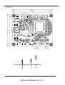
1
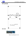
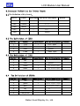
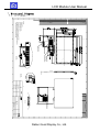
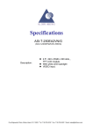
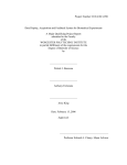
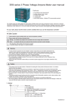
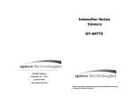
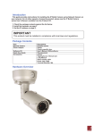
LCD MODULE SPECIFICATIONS
SPEC NO
GD43QMD-GTT050RDH03
REV NO
Good Display
Good Display
Specifications
Type:
Model No.
Standard
GD43QMD-GTT050RDH03
Description:
5.0”, 480 x RGB x 272 dots,
TFT LCD module.
With white LED backlight
VGA and VIDEO signal input.
Prepared:
Checked:
Approved:
Issue Date:
Xiaoli Lan
Moon Wu
Boris Jen
2008.07.10
Dalian Good Display Co., Ltd.
Good Display
No.17 Gonghua Street, Shahekou District, Dalian 116021 China
Tel: +86-411-84619565 Fax: +86-411-84619585
E-mail: [email protected]
Website: www.good-lcd.com
www.good-lcd.com.cn
Dalian Good Display Co., Ltd.
1.01
LCD Module User Manual
Catalogue
Content
2
Version
3
1. Profile
4
2. Application
4
3. Main Parameter
4
4. Block DiagramˈProduct Picture
5
5. Wiring Diagram
6
6. Connection Definition of Driver Board
6-9
7. Structural Diagram
10-11
8.5.0" TFT LCD Panel Inspection Standard
12-13
9. Packing
14
10. Attention
14
Dalian Good Display Co., Ltd.
LCD Module User Manual
Version
Date
Version
2008-4-30
VER:1.00
2008-7-10
VER:1.01
Content
GTH043I9W1-A**
Dalian Good Display Co., Ltd.
LCD Module User Manual
1. Profile˖
GD43QMD-GTT050RDH03 5.0" color TFT lcd module is composed of driver board LQ035NC111AD-HW and 5.0" digital TFT display: GTT050RDH03. This module provides users with Video
and VGA signal input and automatic identifying and converting of NTSC/PAL systems, built-in OSD
(on-screen display) function, and the OSD menu offers adjustment of brightness, contrast and color.
The power control IC is designed for better reliability.
2. Application˖
Ɣ
Ɣ
Ɣ
Ɣ
Ɣ
Ɣ
Office electronic equipment
Apparatus & measurement appliance
Machinery
Audiovisual ˄Display for carǃProtable DVDǃLong-distance terminalǃLcd TV˅
Home appliance ˄Video door phoneǃVideo telephone˅
Don’t use it for high-sophisticated product which need high requirement in term of
reliability & stability &accuracy.
3.Main Parameter˖
Ɣ
Ɣ
Ɣ
Ɣ
Ɣ
Ɣ
Ɣ
Ɣ
Ɣ
Ɣ
Ɣ
Ɣ
Ɣ
Ɣ
Product Name˖5.0" TFT LCD module
Product Model˖GD43QMD-GTT050RDH03
TFT Display˖5.0ʾTFT LCD display: GTT050RDH03
Backlight˖LED
Resolution˖800×RGB×480
Luminance˖250 cd/m2
View angle˄U/D/L/R˅
˖
˄50/70/70/70˅
Power supply voltage ˖DC9~15V˄Type12V 280mA±20mA ˅
Active Area (mm)˖108.00(H)x64.8(V)
Outside dimension of display(mm)˖120.70(W)×75.80
˄H˅×3.10(D˅
Structural dimension of PCB(mm)˖80(W)×67.1˄H˅×15(D˅
Operation temperature˖-20~70ć
Relative humidity˖5~95% RH
Storage temperature˖-30ć~+80ć
Dalian Good Display Co., Ltd.
LCD Module User Manual
4. Block Diagram˖
Deinterlacer/scalor
CN202
J102
TCON
flash
J202
DC TO DC
Product Picture˖
Dalian Good Display Co., Ltd.
5.0
Video
Decoder
ᇌ
᭄
ᄫ
ሣ
LCD Module User Manual
:LULQJ'LDJUDP
3
83Ė'201Ę
.H\ERDUG˖
Dalian Good Display Co., Ltd.
LCD Module User Manual
&RQQHFWRU'HILQLWLRQIRU'ULYHU%RDUG˖
The Definition of Key board˖
Symbol
Pin No.
Input/Output J201 Pin No Description
SW4
SOURCE
I
SW5
POWER
I
SW6
MENU
I
SW7
+
I
3OXV
SW8
-
I
reduce
Remark
6ZLWFK
7KH'HILQLWLRQRI-˖
3LQ1R 6\PERO,QSXW2XWSXW3LQ1R'HVFULSWLRQ 5HPDUN
1
+12V
I
+12V Input
2
GND
-
ground
3
GND
-
ground
4
CVBS
I
Video input
7KH'HILQLWLRQRI-˖
3LQ1R 6\PERO
,QSXW2XWSXW3LQ1R'HVFULSWLRQ5HPDUN
1
NC
2
GND
-
ground
3
SAR0
I
NH\ERDUGLQSXW
4
SAR1
I
NH\ERDUGLQSXW
7KH'HILQLWLRQRI&1˖
3LQ1R 6\PERO ,QSXW2XWSXW 3LQ1R'HVFULSWLRQ 5HPDUN
1
red
I
UHG6LJQDOLQSXW
2
green
I
JUHHQ6LJQDOLQSXW
3
blue
4
NC
1&
5
NC
1&
6
red ground
I EOXH6LJQDOLQSXW
-
Dalian Good Display Co., Ltd.
LCD Module User Manual
7
green ground
-
8
blue ground
-
9
NC
10
ground
11
NC
NC
12
1&
13
NC
H sync
I
14
V sync
I
15
NC
1&
-
1&
6.5 The Definition of J100˖
Pin
Symbol
I/O
Function
1
VLED-
I
LED Ground
2
VLED+
I
LED Power
3
DGND
I
Digital Ground
4
VDD
I
Power Supply (+2.5 V)
5
R0
I
Red Data Bit0
6
R1
I
Red Data Bit1
7
R2
I
Red Data Bit2
8
R3
I
Red Data Bit3
9
R4
I
Red Data Bit4
10
R5
I
Red Data Bit5
11
R6
I
Red Data Bit6
12
R7
I
Red Data Bit7
13
G0
I
Green Data Bit0
14
G1
I
Green Data Bit1
15
G2
I
Green Data Bit2
16
G3
I
Green Data Bit3
17
G4
I
Green Data Bit4
18
G5
I
Green Data Bit5
19
G6
I
Green Data Bit6
20
G7
I
Green Data Bit7
21
B0
I
Blue Data Bit0
22
B1
I
Blue Data Bit1
Dalian Good Display Co., Ltd.
Remark
LCD Module User Manual
23
B2
I
Blue Data Bit2
24
B3
I
Blue Data Bit3
25
B4
I
Blue Data Bit4
26
B5
I
Blue Data Bit5
27
B6
I
Blue Data Bit6
28
B7
I
Blue Data Bit7
29
DGND
I
30
DCLK
I
Dot Data Clock
31
DISP
I
Display On/Off
32
Hsync
I
Horizontal Sync Input
33
Vsync
I
Vertical Sync Input
34
DE
I
Data Enable Control
Digital Ground
35
NC
I
no connect
36
DGND
I
Digital Ground
37
NC
38
NC
39
NC
40
NC
Dalian Good Display Co., Ltd.
Note 1
Note 2
LCD Module User Manual
6WUXFWXUDO'LDJUDP
TFT 3$1(/
NO.
1
2
3
4
5
6
7
8
9
10
11
12
13
14
15
16
17
18
19
20
21
22
23
24
25
26
27
28
29
30
31
32
33
34
35
36
37
38
39
40
PIN NAME
VLEDVLED+
GND
VDD
R0
R1
R2
R3
R4
R5
R6
R7
G0
G1
G2
G3
G4
G5
G6
G7
B0
B1
B2
B3
B4
B5
B6
B7
GND
CLKIN
STBYB
HSD
VSD
DEN
NC
GND
XR
YD
XL
YU
1
NOTES:
1.Display:TFT;
2.Viewing Direction:12:00;
3.General Tolerance:±0.20;
4.Requirements on Environm ent Protection: Q/S0002
5.Recommended Case Open Ar ea should be less than Module V. A
6. Connector size: FH19SC-40S-0.5SH (HRS)
YU YD
XL XR
Thickness 1.3max
Component Araea
40
See Detail "A"
1
A K
See Detail "B"
Thickness 1.0max
DETAIL: A
SCALE: 4:1
40
YU YD
XL XR
DETAIL: B
SCALE: 4:1
Wei Shu
Wei Fang
Wei Zhou
REV
LED K
EC NUMBER
BLU circuit
DATE
1/1
1:1
Dalian Good Display Co., Ltd.
DESCRIPTION
LED A
Single Layer
LCM
YGT1-00
TM050RDH01-00
7.2 PCB:
Dalian Good Display Co., Ltd.
8. 4.3" TFT LCD Panel’s Determinant standard:
Aim:Establish the standard of PANLE for inspecting material & progress and
Scope:Apply to 5.0″TFT LCD
Content:
8.1Determinant standard and method:
8.1.1. The method and determinant of inspecting the nick of panel of LCD:
8.1.1.1. Inspect vertically (or at 45°angle from left/right)under the
light tube (the power is 20 W) in the distance of 30cm to the
panel. If there is no nick, it determines “OK”, otherwise
“NG”.
8.1.2. The method and determinative for black & white & color spots for the
Panel of LCD: :
8.1.2.1. Inspecting method
8.1.2.1.1. Black spots:under the situation of “turn on the
light”,set the MASK of black spot inspection
near the black spot then compare the big and
small by eyes.
8.1.2.1.2. White & Color spots: under situation of “turn on
the light”, set the Mask of black spot inspection on
the white spot(or color spot) then observe them by
eyes if it can hide.
8.1.2.2 Division of LCD Panel:
Remark:Area of A1:The center of the available area for the picture
Area of A2:The edge of the available area for the picture(8mm around
the central area)
Dalian Good Display Co., Ltd.
8.1.3. Determinant Choice
Allowed Area
Spot Diameter(mm)
A1
A2
Black Spot
White or color spot
d≤0.15
Negate
Negate
0.15<d≤0.25
4
4
0.25<d≤0.3
2
3
0.5<d<0.8
0
1
d≤0.15
Negate
Negate
0.15<d≤0.25
3
3
0.25<d≤0.3
1
2
0.5<d<0.8
0
1
Remark: 1. Size: Average Diameter=(Max. Diameter + Min. Diameter)/2
2. Using information above as a standard in order to judge while the e spots are
dense.
3. Black & White spot:To judge the obvious spots through the change
of voltage by comparison.
4. Total quantity of Black & white & color spot: A1+A2 ≤ 4.
Dalian Good Display Co., Ltd.
9.Packing:
TBD
10.Attention:
1. Voltage don’t exceed upper limit.
2. The connector can’t connect board in reverse, or will burn the board and influence
the product.
3. Please don’t touch it in order to keep your skin non-burn when you electrify the
board(High voltage on the board).
4. 5.0”TFT LCD Panel, it is a electric product, so you need to take anti-static measure
when you operate it.
5. 5.0”TFT LCD Panel is a glasswork, place carefully, broken for fear.
6. The connection if “FPC”, which connect 5.0”TFT LCD Panel to PCB. Please
operate it carefully, in order to break off for fear.
7. Don’t touch key-press’s pin when you adjust brightness, color through soft
key-press, due to Person’s body have resistance, you will effect image’s impact
when touch it.
Dalian Good Display Co., Ltd.