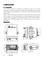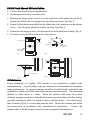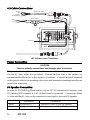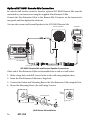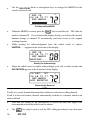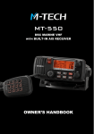
1
MT-700
MENU
OWNER’S
HANDBOOK
DECLARATION OF CONFORMITY
I hereby declare that the product:
Maritime transceiver: MT-700
+ Optional Remote Microphone: MT-RM01
satisfies all the technical regulations applicable to the product within the scope of Council
Directives 73/23/EEC, 89/336/EEC and 99/5/EC:
ETSI EN 301 025-1 V1.3.1: 2007-02
ETSI EN 301 025-2 V1.3.1: 2007-02
ETSI EN 301 025-3 V1.3.1: 2007-02
ETSI EN 301 698-3 V1.1.1: 2001-05
EN 50385: 2002
EN 60945: 2002
ETSI EN 301 843-1 V1.2.1: 2004-06
All essential radio test suites have been carried out.
NOTIFIED BODY:
EMCCert Dr. Rasek
- Address:
Boelwiese 5, 91320 Ebermannstadt, Germany
Identification Number: 0678
MANUFACTURER:
Pony Electric Corporation
- Address:
No. 202, 6-28, Akasaka 9-chome, Minato-ku, Tokyo 107-0052, Japan
This declaration is issued under the sole responsibility of the manufacturer and, if applicable, his
authorized representative.
- Point of contact:
Tadashi Watanabe,
Tel: +81 (0)3 3405 5733
Fax: +81 (0)3 3405 8677
Tadashi Watanabe, President
Tokyo Japan, 17th January 2008
MT-700
1
NOTICE
This device is only and aid to navigation. Its performance can be affected by many
factors including equipment failure or defects, environmental conditions, and
improper handling or use. It is the user’s responsibility to exercise common
prudence and navigational judgment, and this device should not be relied upon as a
substitute for such prudence and judgment. Your MT-700 VHF radio generates and
radiates radio frequency (RF) electromagnetic energy (EME). This equipment must
be installed and operated in accordance with the instructions contained in this
handbook. Failure to do so can result in personal injury and/or product
malfunction.
Antenna Mounting and EME Exposure
For optimal radio performance and minimal human exposure to radio frequency
electromagnetic energy, make sure the antenna is:
Connected to the radio before transmitting
•
Properly mounted
•
Located where it will be away from people
•
Located at least three feet (91 cm) from the Base Station transceiver and handsets.
•
2
MT-700
TABLE OF CONTENTS
DECLARATION OF CONFORMITY ................................................................................1
1. GENERAL INFORMATION ........................................................................................6
Introduction ................................................................................................................................6
2. LICENSE INFORMATION...........................................................................................7
2.1 Digital Selective Calling (DSC) Capability ....................................................................7
2.2. Required License Information.........................................................................................7
2.3 Equipment Required..........................................................................................................7
2.4 Equipment Supplied ..........................................................................................................8
2.5 Optional Equipment...........................................................................................................8
3. BASIC RADIO COMMUNICATION PROCEDURES....................................................9
3.1 Using Channel 16 ................................................................................................................9
3.2 Calling Another Vessel ....................................................................................................10
3.3 Telephone Calls..................................................................................................................10
3.4 Prohibited Communication............................................................................................11
4. INSTALLATION........................................................................................................12
4.1 Transceiver..........................................................................................................................12
Dimentions .......................................................................................................................12
FM-03 Flush Mount Kit Installation ...........................................................................13
4.2 Antenna ...............................................................................................................................13
4.3 Cable Connections ............................................................................................................14
Power Connection ..........................................................................................................14
PA Speaker Connection.................................................................................................14
NMEA Cable....................................................................................................................15
External Speaker Connection.......................................................................................15
Antenna Connector ........................................................................................................15
Optional MT-RM01 Remote Mic Connection..........................................................16
5. OPERATION ............................................................................................................17
5.1 General.................................................................................................................................17
5.2 Display and Controls........................................................................................................17
5.3 Basic Operation..................................................................................................................18
Power On/Off .................................................................................................................18
Volume and Squelch......................................................................................................18
Channel Selection............................................................................................................19
Channel Banks.................................................................................................................19
Keypad, Transceiver.......................................................................................................19
MT-700
3
Keypad, Microphone .....................................................................................................20
5.4 Optional MT-RM01 Remote Mic...................................................................................21
Power On/Off .................................................................................................................21
Volume and Squelch......................................................................................................22
Lamp..................................................................................................................................22
Contrast .............................................................................................................................22
Mic Lock............................................................................................................................22
6. OPERATIONG PROCEDURES..................................................................................23
6.1 Primary Calling Channel.................................................................................................23
6.2 Transmitting........................................................................................................................23
6.3 Working Channel Recall..................................................................................................24
6.4 Transmitter Power Setting...............................................................................................24
6.5 Channel Scanning..............................................................................................................24
Priority Scan .....................................................................................................................25
All Scan..............................................................................................................................25
Memory Scan...................................................................................................................26
6.6 Menu Functions .................................................................................................................27
6.7 Main Menu Topics ............................................................................................................28
Directory............................................................................................................................28
Lamp..................................................................................................................................31
Contrast .............................................................................................................................32
Data Set..............................................................................................................................32
MMSID Set .......................................................................................................................36
ATIS Set.............................................................................................................................37
Time Set.............................................................................................................................37
NMEA Set.........................................................................................................................38
GPS Alert...........................................................................................................................38
CH Name..........................................................................................................................39
Fog Freq.............................................................................................................................40
Mic Lock............................................................................................................................40
CH Change (Automatic CH Change)........................................................................41
7. PA/FOG/INTERCOM OPERATION ...........................................................................42
7.1 PA Hail.................................................................................................................................42
7.2 Fog Horn .............................................................................................................................43
7.3 Intercom...............................................................................................................................44
8. DSC OPERATION ....................................................................................................46
8.1 MMSID ................................................................................................................................46
8.2 Sending a Distress Call.....................................................................................................47
4
MT-700
8.3 Receiving Distress Calls...................................................................................................49
Distress Sent by another vessel....................................................................................49
Distress ACK sent to another vessel...........................................................................51
Distress Relay from another vessel.............................................................................51
8.4 Normal DSC Calls.............................................................................................................52
Individual DSC Call .......................................................................................................52
Directory Call...........................................................................................................52
Manual Call..............................................................................................................55
All Ship's Call...................................................................................................................57
Group Call ........................................................................................................................58
Position Send....................................................................................................................59
Position Request..............................................................................................................60
8.5 Receiving DSC Calls.........................................................................................................62
Individual Call Received...............................................................................................63
Last Call Received...........................................................................................................64
All Ship's Call Received.................................................................................................65
Group Call Received ......................................................................................................67
Position Send Received..................................................................................................67
Position Request Received............................................................................................68
9. ATIS OPERATION....................................................................................................69
9.1 ATIS Set ...............................................................................................................................69
9.2 ATIS ID ................................................................................................................................70
10. REFERENCE...........................................................................................................71
10.1 Maintenance.....................................................................................................................71
10.2 Special Functions.............................................................................................................71
Clear Memory Channels...............................................................................................71
New Microphone............................................................................................................71
Printer Operation ............................................................................................................71
10.3 Troubleshooting ..............................................................................................................72
10.4 Specififcations...................................................................................................................73
10.5 Channel Assignments....................................................................................................77
MT-700
5
1. GENERAL INFORMATION
Congratulations on your purchase of the MT-700. It is an advanced marine VHF
communication transceiver offering Digital Selective Calling, a separate Channel 70
receiver, an easy to use four line LCD display, PA Hail/Fog Horn functions, and
optional Remote Mic capability.
NOTICE
Unauthorized changes or modifications to this equipment may void compliance with
Regulatory Agency Type Acceptance. Any changes or modification must be
approved in writing by the manufacturer.
NOTICE
This radio transceiver has been tested and complies with EN-301 025-1 v1.3.1
(February 2007). This specification provides reasonable protection against harmful
interference in a normal installation. This radio generates, uses and radiates radio
frequency energy and, if not installed and used in accordance with the instructions,
may cause harmful interference to other marine electronic equipment. However,
there is no guarantee that interference will not occur in a particular installation. If this
radio does cause harmful interference to marine electronic equipment, which can be
determined by turning this radio Off and On, the user is encouraged to try to correct
the interference by one or more of the following measures:
•
Reorient or relocate the antenna.
•
Increase separation between this radio and other marine electronic equipment.
•
Connect this radio to a power source different from that of other marine
electronic equipment.
•
Consult your dealer or an experienced technician for help.
Introduction
Your MT-700 VHF Transceiver is designed for operation in the marine VHF FM
frequency band. The operating frequency range is 156.025 to 162.000 MHz which
includes all currently allocated International channels.
The transceiver has Digital Selective Calling (DSC) capabilities conforming to EN-301
025-1 v1.3.1 operation. Distress, All Ships, Individual and Group DSC call formats
are supported. There are thirty two memories for storing incoming DSC calls and
thirty two for your personal DSC call directory.
Also transceiver has the built-in PA Hail/Fog Horn features, and full remote control
6
MT-700
capability including Intercom operation with optional MT-RM01 Remote Mic.
Other features include Position Send/Request, all channels scanning, priority channel
scanning, memory channel scanning, one button instant access to channel 16 and an
alphanumeric keypad on the microphone.
2. LISENCE INFORMATION
Your MT-700 complies with European Standard EN-301 025-1 v1.3.1. Users must
know and comply with all applicable rules and regulations for the country or
countries having jurisdiction over waters where your transceiver is operated.
Depending upon national regulations, a station license may be required for a VHF
transceiver and an operator license or permit may be required for an individual to
operate a VHF transceiver.
Prior to using your MT-700 inquire with your national radio communication
authorities.
2.1 Digital Selective Calling (DSC) Capability
You must obtain a nine-digit maritime mobile service identity (MMSI) and program it
into the unit before you transmit. To obtain an MMSI, you will be asked to provide
certain information about your ship. It is important that you obtain an MMSI
because National Coast Guards and other search and rescue (SAR) agencies use this
information to help speed search and rescue operations.
2.2 Required License Information
The following information pertaining to your transceiver is necessary if completing a
station license application
Output Power........................................................................... 1 Watt (low) and 25 Watts (high)
Emission .............................................................................................................16K0F3E, 16K0G3E
Frequency Range......................................................................................156.025 to 162.000 MHz
Meets Essential Requirements of RTTE DIRECTIVE (Declaration of Conformity)
2.3 Equipment Required
The minimum equipment required for two way voice and DSC VHF radio
communication with vessels and shore stations includes:
•
VHF radio communication transmitter and receiver designed and approved for
marine VHF communication use.
MT-700
7
•
VHF antenna and connecting cable. Use a good quality unity gain antenna for
best range performance.
•
Power source suitable for the VHF transmitter and receiver.
•
For PA Hail and Fog Horn features to function, connection to an extra PA
Speaker (30W nominal at 13.6V/4Ohm).
•
For Digital Selective Calling (DSC) VHF communication radios, connection to a
GPS receiver that provides latitude and longitude coordinates and UTC time for
distress messages.
2.4 Equipment Supplied
•
MT-700 Marine VHF Transceiver.
•
Microphone with alphanumeric keypad.
•
Mounting Bracket with knobs.
•
Power Cable with in-line fuse (6.3 Amp).
•
NMEA Data Cable.
•
FM-03 Flush Mount Kit.
2.5 Optional Equipment
•
8
MT-RM01 Remote Mic.
MT-700
3. BASIC RADIO COMMUNICATION PROCEDURE
Distress or emergency calls may be made either manually or automatically. Sending
distress calls automatically uses the Digital Selective Calling (DSC) functions of your
transceiver and requires an operating and properly connected navigation receiver.
The following procedures are for sending voice distress messages manually.
Sending an automatic distress call is described in the DSC section of this manual.
3.1 Using Channel 16
Channel 16 is the Calling and Distress channel. An emergency may be defined as a
situation that threatens human life or property. In such situations, make sure your
transceiver is turned On and set the channel selector to Channel 16. Then use the
following procedure to make a distress call. The total transmission should not exceed
1 minute.
1.
Press the microphone Push To Talk button. Speak slowly and clearly into
the microphone: “Mayday, Mayday, Mayday, this is your vessel’s name,
your vessel’s name, your vessel’s name”.
2.
Then repeat once: “Mayday, your vessel’s name”.
3.
Continue by reporting your position in latitude and longitude or by
reporting your bearing (true or magnetic, specify which) and distance from
a prominent or well known landmark, geographic feature or aid to
navigation.
4.
Explain the nature of your emergency (fire, sinking, collision, grounding,
health condition, injury, etc.).
5.
Report the kind of assistance you require (fire, medical aid, pumps, etc.).
6.
State the number of people aboard and the condition of any injured.
7.
Estimate the seaworthiness and condition of your vessel.
8.
Describe your vessel: length, type, color and any distinguishing feature.
9.
End the message by saying “Over”. Release the Push To Talk button and
listen for a reply.
10.
If there is no reply, repeat the above message procedure. If there is still no
response, try another channel.
MT-700
9
3.2 Calling Another Vessel
Channel 16 may be used to establish initial contact with another vessel. However, its
most important use is for voice emergency messages. Channel 16 must be monitored
at all times except when engaged in actual communication on another channel.
Channel 16 is monitored by international search and rescue (SAR) authorities,
National Coast Guards and by other vessels. Use of Channel 16 for calling or hailing
must be limited to initial contact only. Calling should not exceed 30 seconds and
may be repeated 3 times at 2 minute intervals.
Prior to making contact with another vessel, determine which channel will be used for
continued communication after the initial contact. Monitor the desired channel for
traffic and, when clear, switch to Channel 16 to make initial contact.
Listen for traffic on the Calling Channel (16). If clear, press the Push To Talk (PTT)
button on the microphone. Speak the name of the vessel you are calling followed by
“This is” and the name of your vessel and your call sign. Release the PTT and listen
for a reply. When the other vessel returns your call, acknowledge the call with “go
to”, the number of the new channel and “over”. Switch to the new channel and listen
for traffic. If necessary, wait for traffic to clear, and then call the other vessel. As
communication proceeds, end each transmission with “over”. When communication
with the other vessel is completed, end the last transmission with your call sign and
the word “out”. It is not necessary to end each transmission with your call sign, just
give your call sign at the beginning and end of each contact.
Remember to switch to Channel 16 when not actively communicating on another
channel.
3.3 Telephone Calls
You may use your MT-700 transceiver to make telephone calls to persons on shore.
To do so requires the services of marine operators who operate on designated Public
Correspondence channels. There are several channels designated for this type of
traffic and to determine the channel being used in your area, ask someone with local
knowledge, contact a Harbor Master or other marine authority.
Call the marine operator and identify yourself with your vessel’s name. Normally
you contact a marine operator on their working channel rather than making initial
contact on Channel 16. The marine operator will ask for your intentions and
establish a payment method for the call (collect, credit card, etc.). When
arrangements are complete, your radio communication will be patched into the
telephone line. In conversing with a person on the phone it is important to use
10
MT-700
normal radio communication procedures. You should say ”over” and release the
Both parties cannot speak
PTT button at the end of each transmission.
simultaneously as on normal telephone calls.
Usually there is a fee for marine operator services which is charged in addition to any
other charges associated with the call.
3.4 Prohibited Communication
The following communications are prohibited by regulations and violators are subject
to penalties.
•
False distress or emergency messages (including false DSC distress).
•
Messages to “any vessel” except in emergencies and radio tests.
•
Messages to or from a vessel on land.
•
Transmission while on land.
•
Obscene, indecent, or profane language.
MT-700
11
4. INSTALLATION
4.1 Transceiver
Your MT-700 Transceiver is designed to withstand the rigors of the marine
environment. However, selecting a mounting location affording some protection
from the elements will prolong the life of connectors, controls and the liquid crystal
display (LCD).
Select a location within easy reach and view of the operator and away from your
vessel’s compass. Locate the microphone to avoid entanglement with steering or
engine controls, both when in use and when stowed. Also, consider routing of
antenna, power and NMEA interface cables. Mount the transceiver securely to a
solid surface.
Dimensions
216.8 mm
126 mm
191 mm
151.5 mm
6 mm dia.
98.7 mm
32 mm
177.2 mm
174.4 mm
12
MT-700
156 mm
69 mm
91.2 mm
MENU
25.9 mm
117.1 mm
60.8 mm
FM-03 Flush Mount Kit Installation
1. Cut the dash board using a template sheet.
2. Set the transceiver in the cut dash board.
3. Rotating the longer screw and set it to the each hole of the plastic mount block.
Firmly attach the bolt foot rotating to the top of the each screw. (See Fig. 1)
4. Firmly fix the plastic mount block on the either side of the transceiver using shorter
screw. Don’t forget to attach the washer. (See Fig. 2 and Fig. 3)
5. Fasten the each longer screw to fix the transceiver to the dash board firmly. (Fig. 4)
6. The same works should be done to the other side too.
Longer screw
Bolt foot
Washer
Shorter screw
Plastic mount
block (Top)
Plastic mount
block (Side)
Fig. 1
Fig. 2
㧗
(+) Screw driver
Fig. 3
Fig. 4
4.2 Antenna
Proper installation of a quality VHF antenna is very important to reliable radio
communication. A good quality unity gain antenna is recommended for maximum
range performance. In general, antennas should be located as high as practical and
separated as much as possible from other antennas and structures. The minimum
distance to other objects is 1 meter. Route the antenna cable away from other
electronic equipment and do not bundle the antenna or power cable with other wiring,
especially transducer cables for depth sounders and fish finders. For cables longer
than 10 meters, RG-8/U coaxial cable must be used. Mount the antenna and install
the connector(s) in accordance with manufacturer’s instructions. Connect the
antenna cable to the RF output connector on the rear panel of the transceiver.
MT-700
13
4.3 Cable Connections
Brown
Red
Orange
Shield (Black)
NMEA Data Cable
Power Cable
Black
Black
Red
Red
Antenna
White
Black
PA Speaker Connection Wire
MT-700 Rear Panel Connections
Power Connection
CAUTION
Reverse polarity connections can damage your transceiver
The power cable for your transceiver must be connected to the ships main power buss.
Use the 6.3 Amp in-line fuse provided. Connect the Red wire to the positive (+)
terminal and the Black wire to the negative (-) terminal. Connect the barrel terminals
on the power cable to the matching color wires and terminals extending from the rear
panel of the transceiver.
PA Speaker Connection
In order for PA Hail/Fog Horn features of your MT-700 transceiver to function, extra
PA Speaker (30W nominal at 13.6V/4Ohm) must be connected. Connect the White
(+) wire and Black (-) wire on the transceiver’s rear panel to the extra PA Speaker.
Wire Color
Description
Connection
White
PA Speaker (+)
Connect to extra 4 Ohm PA Speaker
Black
PA Speaker (-)
Connect to extra 4 Ohm PA Speaker
14
MT-700
NMEA Cable
In order for the position reporting/transferring features of your MT-700 transceiver to
function, an operating GPS navigation receiver must be connected to your transceiver.
The supplied data cable plugs into the 8 pin connector on the transceiver’s rear panel
and the other end connects to the NMEA data output/input from your GPS
navigation receiver. Your GPS must adapt for the $GPRMC/GGA NMEA data
sentence. Refer to your navigation receiver manual for information about its NMEA
output/input settings and connections.
Wire Color
Description
Connection
1. Brown
NMEA Rx (+)
Connect to NMEA Tx (+) of GPS
2. Red
NMEA Rx (-)
Connect to Ground/NMEA Tx (-) of GPS
3. Orange
NMEA Tx (+)
Connect to NMEA Rx (+) of GPS
4. Shield
Ground/NMEA Tx (-)
Connect to Ground/NMEA Rx (-) of GPS
Pins 3 & 4 reserved for DSC/PC printer interface
Pins 5-8 reserved for Flash programmer
External Speaker Connection
Provision for connecting and external speaker is provided on the rear panel. Use an 8
Ohm speaker rated for at least 3 Watts and suitable for the environment at the chosen
location.
3.5 mm Phone plug
Tip
Audio Out (+)
Body
Audio Out (-)
Antenna Connector
The transceiver is fitted with a type SO 239 female connector which mates with a PL
259 male connector supplied with VHF marine antennas.
MT-700
15
Optional MT-RM01 Remote Mic Connection
In order for full remote control to function, optional MT-RM01 Remote Mic must be
connected to your transceiver using the supplied 10m Extension Cable.
Connect the 10m Extension Cable to the Remote Mic Connector on the transceiver’s
rear panel, and then tighten the cable nut.
You can also connect an External Speaker to the MT-RM01 Remote Mic.
Extension Speaker
MT-RM01
Remote Microphone
MT-RM01
or
MT-700 (Rear)
Remote Mic Connector
10m Extension Cable
MT-RM01 Remote Mic and External Speaker Connections
Other end of 10m Extension Cable can be installed into a wall as a wall socket:
1. Make a large hole, and drill 3 screw holes on the wall using template sheet.
2. Insert the 10m Extension Cable into a large hole.
3. Connect the Gasket and Mounting Base to the 10m Extension Cable using the Nut.
4. Mount the Mounting Base to the wall using 3 screws.
Mounting Base
Nut
Wall
10m Extention Cable
Gasket
Wall Mount Kit Installation
16
MT-700
5. OPERATION
5.1 General
Your MT-700 is an advanced marine VHF communication transceiver offering the
safety and convenience of Digital Selective Calling in addition to all the useful features
found in the best conventional VHF radios.
5.2 Display and Controls
The transceiver is operated using the front panel controls, the keypad, the Push To
Talk (PTT) button and a keypad on the microphone. The 4-line LCD displays the
current operating status, menus for selecting functions, and settings for optional
features. The microphone has a keypad for changing channels and selecting
functions.
Internal Speaker
Microphone
Cable Entry
Squelch Control
Power Switch/Volume Control
LCD Display
Channel/data
Selector
Keypad
Emergency Button
Under Cover
MT-700
mic
Channel
is being used
Frequency Bank
Annunciators
BUSY USA INT CAN
Mic Key Lock
Annunciator
MT-700
4 lines, 11 characters each
for alphanumeric information
Channel
Number
Liquid Crystal Display
MT-700
17
5.3 Basic Operation
Power On/Off
Power to the transceiver is controlled with the PWR/VOL knob.
To turn the transceiver On:
•
Press and hold the PWR/VOL knob. The LCD backlight illuminates and the
Power-On screen appears.
INT
MT-700
CODE 000.00
Power-On Screen
After approximately two seconds, the Normal Communication screen appears in the
display.
16 PRI. HI
MEM CHANNEL
N 28 04.814
W 83 42.169
INT
16 PRI. HI
MEM CHANNEL
99 99.999
999 99.999
Normal Com Screen
Normal Com Screen
with GPS Connected
w/o GPS connected
INT
To turn the transceiver Off:
•
Press and hold the PWR/VOL knob until the LCD turns off.
Volume and Squelch
The Volume and Squelch controls have each knob. They are independent controls but
work together to control audio output from the speaker. The volume control sets the
loudness of sound from the speaker and the squelch control is used to mute
background noise when no received signals are present.
To properly set the Volume and Squelch controls:
•
Rotate the SQ knob fully CCW.
•
Rotate the PWR/VOL knob CW until background noise is plainly heard.
•
Slowly rotate the SQ knob CW until the noise is muted (squelched). Then adjust
the control slightly more CW (approximately 1/8 turn). Use care not to set the
SQ control more CW than necessary or weak signals may not be heard.
18
MT-700
Some channels exhibit more background noise than others, so it may be necessary to
readjust the squelch setting when changing channels or when scanning.
Channel Selection
When the transceiver is turned On, the Primary Calling Channel (channel 16) is
selected.
There are three ways to change channels:
•
(SELECT/ENT) knob, press and hold the
Rotate the
or
keys,
or directly enter the channel number using the numeric keys on the microphone.
The
and
keys will always change channels except when being
used to enter or edit a directory page.
Channel Banks
Your MT-700 is designed for use with the International VHF marine channel
frequencies plus authorized local channel frequencies. Only authorized dealers can
program other approved country channels, where specifically allowed by government
regulations, by using the 8 pin com connector.
Keypad, Transceiver
A tone is emitted each time a key is pressed. A three beep error tone is emitted when
a key is not allowed. Some functions require a key to be pressed and held. After the
hold period times out, a second tone is emitted as the function is entered. The basic
purpose for each key follows. Detailed usage of keys is described in operating
procedures for the transceivers various functions.
Initiates DSC operation screens by pressing. Also opens menu to select
optional settings to personalize your transceiver’s operation by pressing and
hold.
Used to complete editing or selection of options from menu.
Used to toggle transmitter power between 25 watts and 1 watt output.
Certain channels are restricted to 1 watt maximum power and will cause the
error beep if the HI/LO key is pressed.
MT-700
19
Selects the Primary Calling Channel 16 or the last channel used. Also,
cancels DSC and Emergency/Distress calls.
Can be used alone or with the MEM key to select Priority Scan, Memory
Scan or All Scan.
Stores channels in the scan memory bank, and when used with the SCAN
key, starts Memory Scan.
Cancels DSC calls and Emergency/Distress calls.
Initiates PA/FOG menu screen by pressing.
Also initiates Intercom
operation mode by pressing and hold.
Keypad, Microphone
The microphone keypad is used to change channels by directly entering the actual
channel number with the
through
keys.
The
or
keys
step or scroll to a new channel. The microphone keys are used to enter alphanumeric
characters and symbols shown in the following chart.
20
MT-700
5.4 Optional MT-RM01 Remote Mic
The optional MT-RM01 Remote Mic works as a second station of your MT-700
transceiver. You can operate all functions including DSC, PA Hail, Fog Horn and
Intercom. It has common usability to your MT-700 transceiver (except some
operations) with same Keypad, SELECT/ENT dial and four lines LCD display.
Top Keys
PTT
Button
Distress Key (Back)
Frequency Bank
Annunciators
UIC
Channel
Number
Mic Key Lock
Annunciator
4 lines, 11 characters each
Channel is
for alphanumeric information being used
MT-RM01
Liquid Crystal Display
Power On/Off
To turn the MT-RM01 Remote Mic On/Off:
•
Press and hold the
key.
NOTE
Power On/Off of MT-RM01 Remote Mic is working together with your MT-700
transceiver. When powering On/Off the MT-RM01 Remote Mic, MT-700 transceiver
is also powered On/Off. When powering On/Off the MT-700 transceiver,
MT-RM01 Remote Mic is also powered On/Off.
MT-700
21
Some controls like VOLume, SQuelch, LAMP, CONTRAST and MIC LOCK work
separately from your MT-700 transceiver:
Volume and Squelch
The VOLume and SQuelch controls work separately from MT-700 transceiver.
To set the VOL control:
•
Press the
volume.
key. Rotate the SELECT/ENT dial to increase or decrease the
To set the SQ control:
•
Press the
squelch level.
key. Rotate the SELECT/ENT dial to increase or decrease the
LAMP
The LAMP adjustment works separately from MT-700 transceiver, but how to adjust is
same as MT-700. See the LAMP topic of 6.7 Main Menu Topics section.
CONTRAST
The CONTRAST adjustment works separately from MT-700 transceiver, but how to
adjust is same as MT-700. See the CONTRAST topic of 6.7 Main Menu Topics
section.
MIC LOCK
In order to prevent accidental key operation, Keypad (except PTT, DISTRESS keys and
SELECT/ENT dial) of your MT-RM01 Remote Mic may be locked.
•
Press and hold the SELECT/ENT dial. MIC LOCK annunciator appears in the
display.
16 PRI. HI
MEM CHANNEL
N 28 04.814
W 83 42.169
I
Mic Key Lock annunciator
To unlock the Keypad:
•
22
Push and hold the SELECT/ENT dial until MIC LOCK annunciator is gone.
MT-700
6. OPERATING PROCEDURES
6.1 Primary Calling Channel
VHF Channel 16 (156.8 MHz) is the Distress Safety and Primary Calling Channel. All
vessels, not actively engaged in communication, are required to maintain a listening
watch on Channel 16.
6.2 Transmitting
The transmitter is activated, for normal voice communications, by pressing the Push
To Talk (PTT) button on the microphone. Always listen for moment on a channel
before transmitting. If the channel is busy, do not transmit until the channel is clear.
For DSC calling and Distress calls, the transmitter is activated automatically during the
appropriate operating procedure. After DSC contact is established, proceed as in
normal voice communication. Continuous transmitter operation is limited to five
minutes and the transmitter will automatically stop.
To establish normal voice communication:
•
Press the
key to select the Primary Calling Channel.
The Primary
Calling Channel is 16. The Primary Calling Channel number appears in the
upper left corner of the display.
•
Listen on the Primary Calling Channel to make sure the channel is clear.
•
Press the PTT button. Speak directly into the microphone in a normal tone of
voice --clearly--distinctly. Say “(name of vessel being called) THIS IS (your
vessel’s name and call sign).”
•
Release the PTT button and listen for a reply.
•
Once contact is made on the Primary Calling Channel, each vessel must switch to
a working channel to continue conversation. Refer to the channel chart for
proper usage.
•
After communication is completed, each vessel must give its call sign or vessel
name and switch to the Primary Calling Channel and resume listening watch.
MT-700
23
6.3 Working Channel Recall
Rather than using the SELECT/ENT knob or microphone keys to change channels, this
feature allows quick switching between the last working channel and the current
primary channel.
To quickly switch between the last working channel and the Primary Calling Channel:
•
Use the SELECT/ENT knob or microphone keys to select a working channel, such
as channel 68.
•
Press the
key momentarily.
The current primary channel number
appears in the channel number display.
•
Press the
key again momentarily.
The working channel number
appears in the display. Each time the key is pressed, channel selection toggles
between the primary channel and the working channel.
6.4 Transmitter Power Setting
The transmitter has two power settings, 25 watts or 1 watt, which are indicated by HI
or LO appearing in the upper line of the display. The normal power setting is HI for
all channels where 25 watts is allowed. Use the 1 watt setting for communication
with nearby vessels (bridge-to-bridge) or facilities (drawbridges).
•
Press the
key to toggle transmitter power between 25 watts and 1 watt
output.
SPECIAL NOTE
Channels 15, 17, 75 and 76 are restricted to 1 watt maximum power and will cause the
error beep if the HI/LO key is pressed.
6.5 Channel Scanning
There are three channel scanning modes; Priority Scan, All Scan and Memory Scan.
In the Priority Scan mode, Channel 16 is checked for activity every 2 seconds, even if,
the scan is halted by traffic on a working channel. When scanning is halted by traffic,
the scan pauses while the channel is active. Scanning resumes, after a brief delay
when the channel is clear. If the PTT is pressed, in reply to a received signal, scanning
is cancelled.
24
MT-700
Priority Scan
The Priority Scan function scans the Primary Calling Channel and the last selected
working channel.
To select Priority Scan:
•
Press the
key. PSCAN appears in the upper line of the display and the
two scanned channel numbers appear alternately in the display.
PSCAN
HI
08Dec12:05P
N 28 04.814
W 83 42.169
INT
PSCAN
HI
08Dec12:05P
N 28 04.814
W 83 42.169
INT
Priority Scan Sequence
To exit Priority Scan:
•
Press the
key or press the
key.
All Scan
The All Scan function scans all channels except channel 70. Channel 70 is the Digital
Selective Calling (DSC) channel. Voice traffic is not permitted on this channel. If
noisy or busy channels interfere with scanning, the interfering channels may be
temporarily removed from the scan sequence.
To select All Scan:
•
Press and hold the
key for 2 seconds. ALLSCAN appears in the upper
line of the display. The scanned channel numbers appear in sequence in the
channel number display.
To Exit All Scan:
•
Press the
key or press the
key.
To delete channels from the scan sequence:
•
Push and hold the SELECT/ENT knob while the scan is halted on the offending
channel. Turning the transceiver Off and On, restores all channels to the scan
sequence.
MT-700
25
Memory Scan
Memory Scan allows the user to create and scan a bank of preferred channels.
Channels may be added to or removed from the memory channel bank as desired.
Memory channels are stored individually and may be deleted individually, or the
entire bank may be deleted. If the PTT button is pressed, the transceiver exits
scanning and normal communication is resumed.
To create or add channels to the memory channel bank:
•
Press the
key. The Memory Scan channel bank appears in lower two
lines of the display. If no channels have been previously added to the bank, the
Primary Calling Channel (16) is displayed. Otherwise, up to six channel
numbers appear. A plus sign (+) at the end of the lower line indicates more
than six channels are stored in the bank. Press the
key again to advance
to the next page of channels. The memory channel bank can hold all usable
voice communication channels.
ADD/DELETE
MEM CHANNEL
16
INT
ADD/DELETE
MEM CHANNEL
06 09 16
22 67 68 +
Memory Scan Bank
Memory Scan Bank
Default Page
Page Full
INT
ADD/DELETE
MEM CHANNEL
72 78
INT
Memory Scan Bank
Next Page
•
Rotate the SELECT/ENT knob or microphone keys to select a desired channel to
add to the memory channel bank.
•
Press and hold the
key for about two seconds. The selected channel is
stored and the channel number appears in the memory channel bank. Repeat
the select and store process to add more preferred channels. As each channel is
added, the existing channels in the bank shift as necessary to display the new
channel number in the bank.
When in the normal communication mode, as channels are selected, MEM
CHANNEL appears in the second line of the display if the selected channel is
stored as a memory channel.
26
MT-700
16 PRI. HI
MEM CHANNEL
N 28 04.814
W 83 42.169
INT
Memory Channel Display
To remove channels from the memory channel bank:
•
Press the
•
Rotate the SELECT/ENT knob or use microphone keys to select a displayed
channel.
•
Press and hold the
key. The Memory Scan channels appear in the display.
key for about two seconds. The selected channel is
deleted and the channel number is removed from the memory channel bank.
To remove all channels from the memory channel bank:
•
Turn the transceiver Off.
•
Press and hold the
key while turning the transceiver On. The memory
channel bank is erased except for Channel 16 which remains.
To start Memory Scan:
•
Press the
key. The Memory Scan channel bank appears in the display.
•
Press the
key. MSCAN appears in the upper line of the display. The
scanned channel numbers appear in sequence in the channel number display.
6.6 Menu Functions
Menus are used to customize optional settings to individual preference. The
multilevel menu system is a list of topics that, when selected individually, offer
options or additional related topics from which to choose. Changes to menu settings
are stored and remain in force until changed again.
To navigate through menus:
•
Press and hold the
key.
The Main Menu appears in the display.
DIRECTORY is always the first topic displayed on the Main Menu list.
MT-700
27
>DIRECTORY
LAMP
CONTRAST
DATA SET
INT
Main Menu Topics
To select a topic in the menu list:
•
Rotate the SELECT/ENT knob to move the cursor > to the desired topic. There
are more topics than can be displayed at one time, so the list scrolls as the cursor
is advanced beyond the top or bottom of the list.
CH NAME
FOG FREQ.
CH CHANGE
>DIRECTORY
INT
More Main Menu Topics
•
With the cursor on the desired menu topic, press the SELECT/ENT knob.
Options or edit settings for the topic appear in the display.
•
Rotate the SELECT/ENT knob to move the cursor to the desired setting.
•
Push the SELECT/ENT knob to store the new setting.
If you change your mind:
•
Before pressing the SELECT/ENT knob while in an editing mode, press and hold
key to backup to the next higher menu level.
the
To exit the menus and return to communication functions:
•
Press the
key. If the SELECT/ENT knob was not pushed to store a new
value, no changes are made.
6.7 Main Menu Topics
DIRECTORY
The DSC Calling Directory is a list of names and corresponding MMSID’s that you
enter and store for making DSC calls (32 ID’s maximum). Entries to the list can be
added or edited as necessary to keep your directory current.
To add a name and MMSID to the directory:
28
MT-700
•
Press and hold the
•
Push the SELECT/ENT knob. If the directory is empty, the screen appears blank
except for the channel number. If previous entries appear, move the cursor to
an empty line. If no empty line is found, the directory is full and a previous
entry must be overwritten.
•
Push the SELECT/ENT knob. The DIRECTORY NAME/ID screen appears
key. The DIRECTORY topic appears in the display.
with a blinking cursor next to the name line.
INT
DIRECTORY
NAME/ID
>
Name and ID Screen
•
Push the SELECT/ENT knob or
key to move the cursor to the first character
of the name line.
SPECIAL NOTE
Characters are entered in the name and ID fields using either the SELECT/ENT knob or
the microphone keys.
All letters in the alphabet, a space, and the numbers 0~9, plus punctuation marks and
some symbols may be used. The space character follows Z in the alphabet when
using the SELECT/ENT knob. Only numbers are allowed in the ID field.
The following table shows the characters that may be entered in the name field using
the microphone keys.
Several additional special characters are available when entering the name using the
SELECT/ENT knob.
MT-700
29
•
Use the SELECT/ENT knob or microphone keys to select the desired letter,
number or symbol for the first character.
•
If using the SELECT/ENT knob, push the SELECT/ENT knob or
key after
each character is selected to enter the character and advance the cursor to the next
character position.
•
If using the microphone keys, press the appropriate key repeatedly until the
desired character is displayed at the cursor position. Then press the appropriate
key for the next character. The cursor automatically moves to the new position.
When entering the same character in two or more successive character positions,
use the SELECT/ENT knob or
keys to advance the cursor.
•
Use the
•
Up to ten characters are allowed in the name, but only one is required. Enter
enough characters to positively identify the entry.
•
After the last character in the name is selected and entered, push the SELECT/ENT
knob or
•
key if necessary to backspace the cursor.
key again. The cursor moves to the MMSID line.
Push the SELECT/ENT knob or
key to move the cursor to the first digit
position in the MMSID line.
•
Enter the first number in the MMSID. Only numbers 0~9 are allowed in the
MMSID.
•
Press the next microphone number key or push the SELECT/ENT knob to store
the selected digit and move the cursor to the next digit position.
•
Continue to select and store digits until the complete MMSID is entered. After
the last MMSID digit is entered, the cursor returns to the name line of the display.
•
If the name and ID are correct for this directory entry, press and hold the
key to save the data and exit. The directory list appears in the display showing
the new entry by name only. The MMSID does not appear in the directory list.
30
MT-700
To edit an existing name or MMSID in the directory:
•
Press and hold the
•
Push the SELECT/ENT knob. DSC Calling Directory entries appear in the
display. The directory stores a maximum of 32 entries which are displayed four
at a time.
•
Use the SELECT/ENT knob to move the cursor to the entry name for editing.
•
Push the SELECT/ENT knob. The DIRECTORY NAME/ID screen appears
presenting the name and MMSID for the selected directory entry. The blinking
cursor is positioned at the start of the entry’s name.
•
Push the SELECT/ENT knob or
key. The DIRECTORY topic appears in the display.
key. The cursor becomes an underline
instead of a blinking square and moves to the first character position.
•
Use the SELECT/ENT knob to move the underline cursor to the character position
needing change.
•
Push the SELECT/ENT knob or
•
Use the SELECT/ENT knob or microphone keys to change the contents of the
character to the new value.
•
When new value is correct, press the SELECT/ENT knob or the
key. The blinking cursor appears.
key. If
more characters in the same line need changing, use the SELECT/ENT knob or
or
key to move the blinking cursor to the next desired character. If
no more changes are desired on the same line, press and hold the
key to
move the cursor back to the start of the line.
•
When both the name and MMSID are correct, press and hold the
key to
save the data and exit to the directory listing.
LAMP
Allows adjustment of illumination for the LCD display, keypad and microphone
keypad.
MT-700
31
•
Press and hold the
•
Use the SELECT/ENT knob to position the cursor on the LAMP topic.
•
Push the SELECT/ENT knob. The BRIGHTNESS adjust screen appears in the
display.
key. Menu topics appear in the display.
BRIGHTNESS
LO
USA
INT
HI
Brightness Control
•
Use the SELECT/ENT knob or microphone keys 0~3 to change the setting.
•
Push the SELECT/ENT knob or press and hold the
key to store the setting
and exit.
CONTRAST
Allows adjustment of LCD display contrast for best readability in varying lighting
conditions.
•
Press and hold the
•
Use the SELECT/ENT knob to position the cursor on the CONTRAST topic.
•
Press the SELECT/ENT knob. The CONTRAST adjust screen appears in the
display.
key. Menu topics appear in the display.
CONTRAST
LO
USA
INT
HI
Contrast Control
•
Use the SELECT/ENT knob or microphone keys 0~7 to change the setting.
•
Press the SELECT/ENT knob or press and hold the
key to store the setting
and exit.
DATA SET
Provides On/Off control for display of Lat/Lon, Date/Time, Speed/Course, and
32
MT-700
Manual Lat/Lon. Also, provides for entry of Manual Lat/Lon coordinates.
•
Press and hold the
•
Use the SELECT/ENT knob to position the cursor on the DATA SET topic.
•
Push the SELECT/ENT knob.
display.
key. Menu topics appear in the display.
The Data Set menu selections appear in the
LLPOSITION
TIME/DATE
SOG/COG
MANUAL LL
USA
INT
Data Set Selections
•
Use the SELECT/ENT knob or
or
to select either LLPOSITION,
TIME/DATE or SOG/COG. MANUAL LL is described separately.
•
Push the SELECT/ENT knob. The On/Off option is displayed.
•
Use the SELECT/ENT knob or any microphone key to select either On or Off.
•
Push the SELECT/ENT knob to store the selection and exit to the previous menu.
The MANUAL LL data item has 3 options, On/Off/Set. The Set option is used to
manually enter your approximate Lat/Lon position and time of day for distress
messages if your GPS is not connected or not functioning. If Manual Lat/Lon is
turned On, it overrides your GPS Lat/Lon position. Be sure Manual Lat/Lon and
time of day are correctly entered before turning the function On. Time of day is
entered as your local time in either 12 hour or 24 hour format. Its is important that
your local time offset from Universal Coordinated Time (UTC) is set correctly. See
the TIME SET topic on the Main Menu.
To set Manual Lat/Lon:
•
Press and hold the
•
Use the SELECT/ENT knob to position the cursor on the DATA SET topic.
•
Push the SELECT/ENT knob.
display.
key. Menu topics appear in the display.
The Data Set menu selections appear in the
MT-700
33
LLPOSITION
TIME/DATE
SOG/COG
MANUAL LL
USA
INT
Data Set Selections
•
Use the SELECT/ENT knob or
•
Push the SELECT/ENT knob. The MANUAL LL menu appears in the display.
to select MANUAL LL.
or
MANUAL LL
ON
OFF
>SET
INT
Manual LL Menu
•
Use the SELECT/ENT knob to select SET on the menu.
•
Push the SELECT/ENT knob. The SET LL/TIME screen appears.
SET LL/TIME
N
.
W
.
:
LOC
USA
INT
Manual LL Entry
•
Push the SELECT/ENT knob or
key to place the blinking cursor on the first
character (N or S) in the Latitude entry line.
•
Use the
key to toggle N or S to select a hemisphere (North or South)
designator.
•
Push SELECT/ENT knob or
to move the blinking cursor to the next
character in the Latitude entry.
•
Use the SELECT/ENT knob or the microphone keys 0~9 to enter the correct
Latitude value in degrees, minutes and seconds. When Latitude is complete,
the cursor moves to the Longitude line.
•
Press the SELECT/ENT knob or
34
MT-700
key to place the blinking cursor on the first
character (E or W) in the Longitude entry line.
•
Use the
key to toggle E or W to select a hemisphere (East or West)
designator.
•
Push the SELECT/ENT knob or
to move the blinking cursor to the next
character in the Longitude entry.
•
Use the SELECT/ENT knob or the microphone keys 0~9 to enter the correct
Longitude value in degrees, minutes and seconds. When Longitude is complete,
the cursor moves to the Time entry line.
•
Push the SELECT/ENT knob or
to move the blinking cursor to the first
character in the Time entry.
•
Use the SELECT/ENT knob or the microphone keys 0~9 to enter the correct time of
day. LOC appears at the end of the Time line indicating entry must be local
time.
•
Enter your local time in hours and minutes. Use 12 hour AM/PM format if a or
p appear after the minutes characters. The SELECT/ENT knob or the
microphone keys 0~9 toggle the a/p setting. If neither a or p appear in the
Time line, enter your local time, hours and minutes, in 24 hour format.
•
When Lat/Lon and Time values are correct, press and hold the
key to
return to the MANUAL LL menu page.
To turn Manual Lat/Lon On or Off:
•
Use the SELECT/ENT knob to select either On or Off on the MANUAL LL page.
•
Push the SELECT/ENT knob to store the selection.
•
Press the
key.
The Main display appears.
If Manual Lat/Lon is
turned On, and manually entered values are stored, the Lat/Lon values appear
in the lower two lines of the display. The M appearing at the end of the
Longitude line indicates that Manual Lat/Lon is turned On. When Manual
Lat/Lon is turned On, the manually entered position overrides any Lat/Lon
position from a navigation receiver.
MT-700
35
MMSID SET
Provides for entry of the 9 digit MMSI for your vessel which must be entered in order
to make DSC calls. MMSI must be obtained from government communication
authorities or authorized agents.
CAUTION NOTE
Only one entry attempt is permitted. A warning is displayed after the first attempt
and MMSID entry is blocked. CALL YOUR DEALER FOR ASSISTANCE.
To enter your MMSI number:
•
Press and hold the
•
Use the SELECT/ENT knob to position the cursor on the MMSID SET topic.
•
Push the SELECT/ENT knob. The MMSID TYPE menu appears in the display.
key. Menu topics appear in the display.
MMSID TYPE
SHIP ID
GROUP ID
USA
INT
MMSID Type Select
•
Use the SELECT/ENT knob to select SHIP ID on the menu.
•
Push the SELECT/ENT knob. The MMSID SET screen appears in the display.
MMSID SET
000000000
PUSH ENTER
TO CHANGE.
INT
MMSID Set Screen
•
Push the SELECT/ENT knob. The blinking cursor appears at the first digit
position.
•
Use the SELECT/ENT knob or the microphone keys 0~9 to enter your official
MMSI number.
•
When the last digit is selected, push the SELECT/ENT knob or
•
Push the SELECT/ENT knob or
36
MT-700
key.
key again. STORED OK appears briefly in
the lower line of the display completing the entry.
•
Press the
key to return to the Main display.
Follow the above procedure to enter your Group ID number. Group ID entry
attempts are not limited in number.
ATIS SET
See the 9.1 ATIS SET topic of 9. ATIS OPERATION section.
TIME SET
Allows selection of either 12 or 24 hour time format and provides entry of local time
offset from Universal Coordinated Time (UTC), sometimes called Greenwich Mean
Time (GMT). UTC is the time at the Prime Meridian, or zero degrees (0 ゚) Longitude
which passes through Greenwich, England.
•
Press and hold the
•
Use the SELECT/ENT knob to position the cursor on the TIME SET topic.
•
Push the SELECT/ENT knob. The TIME FORMAT menu appears in the display.
key. Menu topics appear in the display.
TIME FORMAT
>12 HR.
24 HR.
88:88
+
INT
Format Selection
•
Use the SELECT/ENT knob to select the desired format, either 12 HR or 24 HR.
•
Push the SELECT/ENT knob. The TIME OFFSET menu appears in the display.
TIME OFFSET
>+00.0
INT
88:88
Time Offset Selection
•
Use the SELECT/ENT knob to set the time difference from the Prime Meridian to
your location. If you are West of the Prime Meridian, select a negative (-) value.
If you are East of the Prime Meridian, select a positive (+) value. Time offset
values from 0 to 12 hours plus or minus may be entered in 1/2 hour increments.
Obtain the time offset value from your GPS navigator.
MT-700
37
•
When your selection is complete, push the SELECT/ENT knob to store the setting
and exit the menu.
NMEA SET
Allows NMEA sentences from navigation equipment manufactured to earlier
versions of the NMEA standard to provide Lat/Lon position coordinates and UTC
time.
•
Press and hold the
•
Use the SELECT/ENT knob to position the cursor on the NMEA SET topic.
•
Push the SELECT/ENT knob. The NMEA CHECKSUM menu appears in the
display.
key. Menu topics appear in the display.
NMEA
CHECKSUM
>ON
OFF
INT
NMEA Checksum Selection
•
Use the SELECT/ENT knob to select either ON or OFF.
•
When your selection is complete, push the SELECT/ENT knob to store the setting
and exit the menu.
GPS ALERT
Provides ON/Off settings for GPS Alert. It is usually set to On. If data from your
GPS navigation receiver is lost, 3 quick error beeps are sounded and **GPS OFF is
displayed on the second line of the Normal Communication screen, alternately with
the date & time and channel name (alternately with MEM CHANNEL and channel
name, in case that displayed channel is memory channel). Press the
or
key to silence the 3 quick error beeps.
To set the GPS Alert:
•
Press and hold the
•
Rotate the SELECT/ENT knob to position the cursor on the GPS ALERT topic.
•
Push the SELECT/ENT knob. The GPS ALERT menu appears in the display.
38
MT-700
key. Menu topics appear in the display.
GPS ALERT
INT
>ON
OFF
GPS Alert menu
•
Rotate the SELECT/ENT knob to select ON or OFF.
•
Push the SELECT/ENT knob to store the setting and exit the menu.
NOTE
Irrespective of this setting, 4 hours and 23.5 hours alert timer is effective. See the 8.
DSC OPERATION section.
CH NAME
Each channel is displayed with default channel name on the second line of the Normal
Communication screen, alternately with the date & time (alternately with MEM
CHANNEL, in case that channel is memory channel). You can edit these channel
names as you like.
To edit the channel names:
•
Select the channel which you want to edit the channel name.
•
Press and hold the
•
Use the SELECT/ENT knob to position the cursor on the CH NAME topic.
•
Push the SELECT/ENT knob. The CH NAME screen appears in the display.
key. Menu topics appear in the display.
CH NAME
SHIP-SHIP
PUSH ENTER
TO CHANGE.
INT
CH Name Screen
•
Push the SELECT/ENT knob. The underline cursor appears at the first character
position.
•
Use the SELECT/ENT knob to move the underline cursor to the character position
needing change.
•
Push the SELECT/ENT knob or
key. The blinking cursor appears.
MT-700
39
•
Use the SELECT/ENT knob or microphone keys to change the contents of the
character to the new value.
•
When the new value is correct, push the SELECT/ENT knob or
•
Up to eleven characters are allowed in the channel name. If more characters
need changing, push the SELECT/ENT knob or
or
key.
key to move the
cursor to the next desired character. If no more changes are desired, push the
SELECT/ENT knob or
key to advance the cursor to the last character.
•
When the last character is selected, push the SELECT/ENT knob or
•
STORED OK appears briefly in the lower line of the display completing the entry.
•
Press the
key.
key to return to the Main display.
FOG FREQ.
Allows selection of tone frequency for Fog Horn operation. Tone frequency is
available to select within the range from 250Hz to 750Hz in 50Hz spacing. The
default tone frequency is 450Hz.
•
Press and hold the
•
Rotate the SELECT/ENT knob to position the cursor on the FOG FREQ. topic.
•
Push the SELECT/ENT knob. The FOG FREQ. screen appears in the display.
key. Menu topics appear in the display.
INT
FOG FREQ
>450Hz
Fog Freq. Selection
•
Rotate the SELECT/ENT knob to select the desired frequency.
•
Push the SELECT/ENT knob to store the setting and exit the menu.
MIC LOCK
In order to prevent accidental channel change, all microphone keys except PTT may be
locked. In MIC LOCK mode, an error beep sounds even if any microphone key
40
MT-700
except PTT is pressed.
•
Press and hold the SELECT/ENT knob. MIC LOCK annunciator appears in the
display.
16 PRI. HI
MEM CHANNEL
N 28 04.814
W 83 42.169
INT
Mic Key Lock annunciator
To unlock the microphone keys:
•
Press and hold the SELECT/ENT knob until MIC LOCK annunciator is gone.
CH CHANGE (Automatic CH Change)
For incoming Distress Call, All Ship’s Distress or Urgency Call, you can select whether
your radio automatically switches to Channel 16 or you determine to manually accept
or decline the channel change.
•
Press and hold the
•
Rotate the SELECT/ENT knob to position the cursor on the CH CHANGE topic.
•
Push the SELECT/ENT knob. The AUTO CH CHANGE menu appears in the
display.
key. Menu topics appear in the display.
AUTO CH
CHANGE
ON
OFF
INT
Auto CH Change menu
•
Rotate the SELECT/ENT knob to select ON or OFF (default is ON).
•
Push the SELECT/ENT knob to store the setting.
MT-700
41
7. PA/FOG/INTERCOM OPERATION
PA Hail, Fog Horn and Intercom operations are available on your MT-700 transceiver.
For PA Hail and Fog Horn operations, you need to purchase and connect an extra PA
Speaker (30W nominal at 13.6V/4Ohm). Intercom operation needs to install the
optional MT-RM01 Remote Microphone.
7.1 PA Hail
PA Hail operation provides a listen-back feature which allows the two-way
communication through the PA Speaker.
To enable the PA Hail operation:
•
Press the
key. The PA/FOG menu appears in the display.
SELECT
>PA
FOG
INT
PA/FOG Menu Topics
•
Push the SELECT/ENT knob. The PA screen (LISTEN mode) appears in the
display.
PA
LISTEN
VOL
LO
INT
HI
PA Screen (LISTEN)
•
Press the PTT button to switch to the HAIL mode. You can speak through the
PA hailer speaker. Use the SELECT/ENT knob to adjust the volume level.
PA
HAIL
VOL
LO
INT
HI
PA Screen (HAIL)
•
42
Release the PTT button to return to the LISTEN mode. To adjust the volume
level on MT-700, rotate the PWR/VOL knob (To adjust the volume level on
MT-700
MT-RM01, use the SELECT/ENT dial after pressing the
•
The
key).
key may be used to exit the PA mode and return to the Normal
Communication screen.
NOTE
While the PA Hail mode is active, you will receive on the last selected channel, and
receive DSC calls. Transmitting on the last selected channel will not operate.
7.2 Fog Horn
Fog Horn operation allows your MT-700 transceiver to emit a various warning signals
through the PA Speaker when the visibility is bad. You can select from the following
4 automatic and 2 manual patterns:
Automatic
Manual
UNDERWAY:
Motor vessel underway and making way.
STOP:
Motor vessel underway but stopped (not making way).
SAIL:
Sailing vessel underway, fishing vessel (underway or
anchored), vessel not under command, a vessel
restricted in her ability to maneuver (underway or at
anchor), or a vessel towing or pushing another ahead.
TOW:
Vessel under tow (manned).
HORN:
Signal for passing.
SIREN:
Yelp type emergency siren.
To enable the Fog Horn operation:
•
Press the
•
Rotate the SELECT/ENT knob to position the cursor on the FOG topic.
•
Push the SELECT/ENT knob. The Fog Horn selections appear in the display.
key. PA/FOG Menu topics appear in the display.
>UNDERWAY
STOP
SAIL
TOW
INT
Fog Horn Selections
•
Rotate the SELECT/ENT knob to select the desired Fog Horn pattern.
•
Push the SELECT/ENT knob.
MT-700
43
Automatic : When you select the UNDERWAY, STOP, SAIL or TOW modes, a
peculiar pattern is automatically emitted. Use the SELECT/ENT knob to adjust
the volume level.
When you select the HORN or SIREN modes, press the PTT button.
Manual :
A continuous tone is emitted while the PTT button is pressed. Use the
SELECT/ENT knob to adjust the volume level.
UNDERWAY
HORN
VOL
LO
HI
INT
UNDERWAY Emitted
•
The
key may be used to exit the Fog Horn mode and return to the
Normal Communication screen.
NOTE
While the Fog Horn mode is active, you will receive on the last selected channel, and
receive DSC calls. Transmitting on the last selected channel will not operate.
7.3 Intercom
When the optional MT-RM01 Remote Mic is installed, you can make a voice
communication between your MT-700 transceiver and MT-RM01 Remote Mic.
To enable the Intercom operation:
•
Press and hold the
key on MT-700 (Press and hold the
key on
MT-RM01). The INTERCOM screen appears in the display. Calling beep tone
is heard on the receiver station, which will be cancelled when the PTT button is
pressed.
INTERCOM
INT
INTERCOM
N 29 06.814
W 82 50.169
N 28 04.814
W 83 42.169
MT-700
MT-RM01
•
Press the PTT button. Speak into the microphone.
•
When finish speaking, release the PTT button and listen for a reply.
44
MT-700
I
•
To adjust the speaker output level on MT-700, rotate the PWR/VOL knob (To
adjust the speaker output level on MT-RM01, use the SELECT/ENT dial after
pressing the
key).
•
The
key on MT-700 (The
key on MT-RM01) may be used to exit
the Intercom mode and return to the Normal Communication screen.
NOTE
While the Intercom mode is active, you will receive on the last selected channel, and
receive DSC calls. Transmitting on the last selected channel will not operate.
MT-700
45
8. DSC OPERATION
The Digital Selective Calling (DSC) functions of your MT-700 transceiver add
convenience and safety to your VHF communication capability. DSC allows you to
contact other DSC equipped vessels and shore stations by selecting their names from
your personal call directory, choosing a call type, and pressing a key. In an
emergency, pressing one button will send your vessel ID and current position to
search and rescue (SAR) authorities and other DSC equipped vessels. Distress calls
are covered first. Then, normal calling procedures are described.
Position reporting requires connection to an operating GPS navigation receiver or
manually entered Lat/Lon coordinates. If data from your GPS is lost, 3 quick error
beeps are sounded and the following warning screen appears in the display every 4
hours.
16 PRI. HI
MEM CHANNEL
SET GPS
DATA NOW!
INT
Set Manual Lat/Lon
This warning screen reminds you to manually enter Lat/Lon coordinates.
See the
MANUAL LL item of the DATA SET topic of the 6.7 Main Menu Topics. If Lat/Lon
coordinates are entered manually but have not been updated for 23.5 hours, the
position fields are set to the repeated “9” and time field is set to the repeated “8”.
8.1 MMSID
SPECIAL NOTE
In order to use DSC functions, you must obtain a nine-digit maritime mobile service
identity (MMSI) and program it into your transceiver before you transmit.
Prior to obtaining an MMSI, you will be asked to provide certain information about
your vessel and communication equipment. Contact the government radio
communication authorities of your country for licensing and MMSI information. It is
important that you obtain an MMSI, because National Coast Guard authorities use
this information to help speed search and rescue operations.
The procedure for entering your MMSI is described in the MMSID SET topic of the
6.7 Main Menu Topics.
46
MT-700
8.2 Sending a Distress Call
To make a Distress Call:
•
Lift the red protective cover, then press and release the red button. The distress
alert screen appears.
DISTRESS!
Undesignated.
HOLD 3 SEC.
USA
INT
Distress Alert Screen
•
If time permits, use the SELECT/ENT knob to select the nature of distress.
DISTRESS!
Grounding.
USA
INT
HOLD 3 SEC.
Select the Nature of Distress
•
Hold the red button (as soon as the button is pressed again, an intermittent
acoustic alarm is sounded and the distress alert screen flashes until the DISTRESS
is sent automatically, in about 3 seconds). Before the distress is sent, you may
release the red button to reset the countdown timer.
•
An alarm sounds and the following screen appears as your distress message is
being transmitted.
MT-700
47
TX
HI
SENDING
DISTRESS!
CALLING.
INT
Sending Distress Call
•
The following screen appears indicating your distress message has been
transmitted.
DISTRESS!
WAITING....
AUTO
RE-TRNSMIT
INT
Distress Call Sent
The DSC distress message is automatically sent on channel 70 and your transceiver is
automatically set to Channel 16 in order to listen for, and respond to, voice replies
from SAR authorities or other vessels which may have received your distress call.
The alarm will sound every 15 seconds to remind you that a distress message is active.
Unless canceled, the distress message is automatically re-transmitted every 3 1/2 to 4
1/2 minutes.
Re-transmissions of DSC distress calls are canceled automatically when a DSC
acknowledgment is received from an authorized SAR coast station, or canceled
manually by you.
To cancel the Automatic Re-transmission of Distress Call:
•
Press the
key. The alarm is stopped, and the Automatic Re-transmission
of Distress Call is cancelled. It does not interrupt the transmission of Distress
Call already in progress. Display reverts to the following screen with the
previously selected nature of distress, and you can attempt to transmit the
Distress Call again at any time.
DISTRESS!
Grounding.
INT
HOLD 3 SEC.
Auto Re-transmission cancelled
48
MT-700
To manually cancel a Distress Call:
•
Press the
key again. The DISTRESS CANCELED message appears in the
display.
INT
DISTRESS
CANCELED.
Manual Distress Cancel
If your Distress Call is acknowledged (ACK) by a coast station:
•
The DISTRESS! CANCELED. ACK RECEIVE screen appears in the display.
DISTRESS!
CANCELED.
CoastSta ID
ACK RECEIVE
INT
Distress Acknowledged
•
Establish voice contact with the coast station on Channel 16.
8.3 Receiving Distress Calls
Your MT-700 transceiver may intercept distress messages sent by another vessel
and/or acknowledgments (ACK) sent by a coast station to another vessel in distress.
In such cases you should maintain a listening watch on channel 16 and standby to
lend assistance. Your MT-700 does not automatically reply to, or relay, distress or
ACK or relay DSC calls.
Distress sent by another vessel
If your MT-700 transceiver intercepts a distress call from another vessel, an alarm
sounds and the screen presents time of distress, MMSID of the distressed vessel, and
Lat/Lon coordinates. The plus sign (+) indicates there is another page of information
available. If invalid GPS or Time data is received, the Lat/Lon position shows “9” in
all digits and the time shows all “8”s.
To accept a Distress Call when Auto CH Change is ON (default):
•
Your transceiver is automatically set to Channel 16.
MT-700
49
Name or ID of
Vessel in Distress
20:33 UTC +
ID323456789
N 28 33.814
W 82 50.169
INT
Distress Alert, page 1
•
Push the SELECT/ENT knob to mute the alert and toggle between page 1 and
page 2. The nature of distress and ALERT call type appear on the second page.
Grounding.
INT
DISTRESS
02 ALERT +
Distress Alert, page 2
To accept a Distress Call when Auto CH Change is OFF:
Name or ID of
Vessel in Distress
20:33 UTC +
ID323456789
N 28 33.814
W 82 50.169
INT
Distress Alert, page 1
•
Push the SELECT/ENT knob. The alert is muted, and your transceiver is set to
Channel 16.
Name or ID of
Vessel in Distress
20:33 UTC +
ID323456789
N 28 33.814
W 82 50.169
INT
Set to Channel 16
•
Push the SELECT/ENT knob to toggle between page 1 and page 2. The nature of
distress and ALERT call type appear on the second page.
Grounding.
DISTRESS
02 ALERT +
Distress Alert, page 2
50
MT-700
INT
Distress ACK sent to another vessel
If your MT-700 transceiver intercepts a distress ACK from a coast station, an alarm
sounds and the following screen appears in the display.
Name or ID of
Coast Station
21:45 UTC +
ID998765432
N 29 06.814
W 82 50.169
USA
INT
Coast Station ACK to other vessel, page 1
The screen presents time of ACK and Lat/Lon coordinates. The plus sign (+)
indicates there is another page of information available.
•
Push the SELECT/ENT knob to toggle between page 1 and page 2.
Name or ID of
Vessel in Distress
INT
EPRIB
Emission.
ID123456789
03 ACK
+
Coast Station ACK to other vessel, page 2
The distressed vessel’s MMSID and ACK appear on the second page. Maintain a
listening watch on channel 16 and standby to lend assistance.
Distress Relay from another vessel
If your MT-700 transceiver intercepts a distress relay from another vessel, an alarm
sounds and the following screen appears in the display.
Name or ID of
Vessel sending
message
04:16P
+
ID323456789
N 28 29.814
W 82 50.169
USA
INT
Distress Relay, page 1
The screen displays, local time of distress, the MMSID of the vessel sending the relay
message and Lat/Lon coordinates of the vessel in distress. The plus sign (+)
indicates there is another page of information available.
•
Push the SELECT/ENT knob to toggle between page 1 and page 2.
MT-700
51
Name or ID of
Vessel in Distress
EPRIB
Emission.
ID123456789
04 RELAY +
INT
Distress Relay, page 2
The distressed vessel’s MMSID and RELAY call type appear on the second page.
Your vessel does not re-send a distress relay message.
8.4 Normal DSC Calls
Your MT-700 can transmit the types of DSC calls; Distress, All Ship’s, Individual, and
Group. Except for Distress, each call type is subdivided into one or more priorities.
All Ship’s type transmits two priorities: Urgency and Safety.
Individual type transmits one priority:
Routine.
Group type transmits one priority:
Routine.
Also MT-700 can transmit the calls of advanced Individual Routine priority; Position
Send, and Position Request. Lat/Lon position from another vessel can be transferred
to the DSC equipped chart plotter, if it is connected.
A normal DSC call may be originated from your vessel to another DSC equipped
vessel or to a coast station, or you may reply to a DSC call sent by another vessel or a
coast station. Outgoing calls are made either by selecting a vessel or station name
from your directory or by manually entering the vessel or station MMSID number
(Position Send and Position Request are made from your directory only).
Replies to any incoming call type can be made directly from the call log. The call log
(LAST CALL) holds thirty two entries and the last call received is on top of the list. If
the call log is full, the oldest entry is lost.
Individual DSC Call
Individual calls can be made to another vessel or to a coast station. It is important to
be able to differentiate between the two. When calling another vessel, the
communication channel is specified in the call by the calling vessel.
If
communicating with a coast station, it is the coast station in its acknowledgment that
determines the channel. Your MT-700 transceiver transmits Routine individual calls,
but receives both Routine and Safety individual calls.
- Directory Call
Directory calls are made by selecting a vessel or station name from the calling
52
MT-700
directory. The calling directory holds thirty two of your previously entered names
that you routinely contact during normal boating activities.
To make a directory call:
•
Press the
key. The DSC calling menu appears in the display with the
cursor indicating INDIVIDUAL topic.
>INDIVIDUAL
GROUP
ALL SHIP'S
RECEIVED
INT
DSC Individual
•
Push the SELECT/ENT knob or press the
key. The INDIVIDUAL menu
appears in the display.
•
Use the SELECT/ENT knob to select the DIRECTORY topic.
INDIVIDUAL
>DIRECTORY
MANUAL
INT
Individual Menu
•
Push the SELECT/ENT knob or press the
key. The directory list appears
in the display.
•
Use the SELECT/ENT knob to select the desired vessel or station name.
Note: The MMSID’s for each entry do not appear in the list.
•
Press the
•
Use the microphone keys to select a working channel.
key. The INDIVIDUAL call screen appears in the display.
NOTE
1) If you operate from MT-RM01 Remote Mic, please select a working channel by the
SELECT/ENT dial on the Normal Communication screen (before entering the DSC
calling menu), because there is no numeric keys on the Remote Mic.
2) If the call is to the coast station, you should not select a working channel. Even if
MT-700
53
you select, MT-700 ignores it when transmits the call.
INDIVIDUAL
vessel name
>ROUTINE
PRESS CALL.
INT
Individual Call Screen
•
Press the
key to send the call. DSC calls are made on channel 70. If
you observe the display closely, you will see the channel number change to
channel 70 momentarily and then revert to the original working channel.
•
While waiting for acknowledgment from the called vessel, WAITING . . . .
appears in the lower line of the display.
INDIVIDUAL
vessel name
>ROUTINE
WAITING....
INT
Waiting For Acknowledge
•
When the called vessel acknowledges your call, an alert sounds and ACK
RECEIVE appears in the lower line of the display.
16 PRI. HI
vessel name
>ROUTINE
ACK RECEIVE
INT
Acknowledge Received
NOTE
If call is to a vessel, channel automatically switches to a selected working channel.
If call is to the coast station, channel automatically switches to a channel which coast
station defined.
•
Press the PTT button on the microphone to silence the alert and begin voice
communication with the called vessel.
•
The
key may be used to exit the DSC calling procedure at any time prior
to sending the call.
54
MT-700
- Manual Call
The manual call procedure is used to make a DSC call to a vessel or station that is not
listed in your calling directory. However, you must know the MMSID for the vessel
or station.
To make a manual DSC call:
•
Press the
key. The DSC calling menu appears in the display with the
cursor indicating INDIVIDUAL topic.
>INDIVIDUAL
GROUP
ALL SHIP'S
RECEIVED
INT
DSC Individual
•
Push the SELECT/ENT knob or press the
key. The INDIVIDUAL menu
appears in the display.
•
Use the SELECT/ENT knob to select the MANUAL topic.
INDIVIDUAL
DIRECTORY
>MANUAL
INT
Individual Menu
•
Push the SELECT/ENT knob or press the
key. The SET CHannel/SET
MMSID screen appears in the display.
•
Use the SELECT/ENT knob or microphone keys to select a working channel.
Four channel numbers appear in the display as suggested channels authorized
for the call to vessel. Other channels may be used if authorized in your area.
NOTE
If the call is to the coast station, you should not select a working channel. Even if you
select, MT-700 ignores it when transmits the call.
•
Push the SELECT/ENT knob. The blinking cursor moves to the first digit in the
MMSID entry field. If the last used manual MMSID is displayed, push the
SELECT/ENT knob once again.
MT-700
55
•
Use the SELECT/ENT knob or microphone keys to change the MMSID for the
vessel or station to call.
SET CH
06 08 72 77
SET MMSID
INT
Set Channel/Set MMSID
•
When the MMSID is correct, press the
key to send the call. DSC calls are
made on channel 70. If you observe the display closely, you will see the channel
number change to channel 70 momentarily and then revert to the original
working channel.
•
While waiting for acknowledgment from the called vessel or station,
WAITING . . . . appears in the lower line of the display.
SET CH
06 08 72 77
SET MMSID
WAITING....
INT
Waiting For Acknowledge
•
When the called vessel or station acknowledges your call, an alert sounds and
ACK RECEIVE appears in the lower line of the display.
16 PRI. HI
06 08 72 77
SET MMSID
ACK RECEIVE
INT
Acknowledge Received
NOTE
If call is to a vessel, channel automatically switches to a selected working channel.
If call is to the coast station, channel automatically switches to a channel which coast
station defined.
•
Press the PTT button on the microphone to silence the alert and begin voice
communication with the called vessel or station.
•
The
56
key may be used to exit the DSC calling procedure at any time prior
MT-700
to sending the call.
All Ship’s Call
The All Ship’s call allows you to send an Urgent or Safety DSC call to nearby vessels
without having to know their MMSID numbers. The All Ship’s call may be used in
situations that are serious but do not warrant a distress call, and voice communication
attempts have failed.
To send an All Ship’s call:
•
Press the
•
Use the SELECT/ENT knob to select the ALL SHIP’S topic.
key. The call menu appears in the display.
INDIVIDUAL
GROUP
>ALL SHIP'S
RECEIVED
INT
DSC All Ship’s Call
•
Push the SELECT/ENT knob or press the
key. The CALL TYPE menu
appears in the display.
CALL TYPE
URGENT
SAFETY
PRESS CALL.
USA
INT
DSC Call Type
•
Use the SELECT/ENT knob to select either URGENT or SAFETY.
•
Press the
key. The Call Type Verification screen appears in the display.
INT
SEND URGENT
CALL?
PRESS CALL.
Call Type Verification
•
Call type must be verified.
MT-700
57
•
Press the
key to send the call. The ALL SHIP’S WAITING . . . . screen
appears in the display. Either URGENT or SAFETY appear to indicate priority of
the call.
INT
ALL SHIP'S
priority
WAITING....
Waiting For Voice Reply
•
Your transceiver is automatically set to Channel 16. Listen for voice replies from
vessels which have received your call. There is no DSC ACK reply to confirm
that your call was received.
•
Use the PTT button to continue voice communication.
Communication screen appears in the display.
•
If there is no response to your call, press the
key.
The Normal
The Normal
Communication screen appears in the display.
Group Call
Your can arrange with other vessels to use a group MMSID so that any vessel in a
group can contact all other vessels in the same group with a single DSC call.
Your group MMSID is stored in the same manner as your ship MMSID. Only one
group MMSID is stored at a time, but group MMSID’s can be changed as often as
desired, allowing participation in more than one group.
To send a DSC group call:
•
Press the
•
Use the SELECT/ENT knob to select the GROUP CALL topic.
key. The call menu appears in the display.
INDIVIDUAL
>GROUP
ALL SHIP'S
RECEIVED
INT
DSC Group Call
•
58
Push the SELECT/ENT knob or press the
MT-700
key. The SET CHannel menu
appears in the display. The current group MMSID appears in the lower line of
the display.
•
Use the SELECT/ENT knob or the microphone keys to select a working channel.
Four channel numbers appear in the display as suggested channels authorized
for this type of call. Other channels may be used if authorized in your area.
SET CH
06 08 72 77
GROUP MMSID
087654321
INT
Set Channel
•
Press the
key. The call is sent and WAITING . . . . appears in the lower
line of the display.
•
Your transceiver is automatically set to the previously set working channel.
Listen for voice replies from vessels which have received your call. There is no
DSC ACK reply to confirm that your call was received.
•
Use the PTT button to continue voice communication.
Communication screen appears in the display.
•
If there is no response to your call, press the
key.
The Normal
The Normal
Communication screen appears in the display.
Position Send
Positin Send can send your Lat/Lon position to another vessel that is listed in your
calling directory.
To make a Position Send:
•
Press the
key. The DSC calling menu appears in the display with the
cursor indicating INDIVIDUAL topic.
•
Push the SELECT/ENT knob or press the
key. The INDIVIDUAL menu
appears in the display.
•
Use the SELECT/ENT knob to select the DIRECTORY topic.
MT-700
59
INDIVIDUAL
>DIRECTORY
MANUAL
INT
DSC Directory
•
Push the SELECT/ENT knob or press the
key. The directory list appears
in the display.
•
Use the SELECT/ENT knob to select the desired vessel name.
Note: The MMSID’s for each entry do not appear in the list.
•
Press the
key. The INDIVIDUAL call screen appears in the display.
INDIVIDUAL
vessel name
>ROUTINE
PRESS CALL.
INT
Individual Call Screen
•
Use the SELECT/ENT knob to select SEND POS.
INDIVIDUAL
vessel name
>SEND POS
PRESS CALL.
INT
Position Send Screen
•
Press the
key to send the call. Call is made on channel 70. If you
observe the display closely, you will see the channel number change to channel
70 momentarily and then revert to the previous working channel.
•
Press the
key to return to the Normal Communication screen.
Position Request
Positin Request can request Lat/Lon position from another vessel that is listed in your
calling directory.
60
MT-700
To make a Position Request:
•
Press the
key. The DSC calling menu appears in the display with the
cursor indicating INDIVIDUAL topic.
•
key. The INDIVIDUAL menu
Push the SELECT/ENT knob or press the
appears in the display.
•
Use the SELECT/ENT knob to select the DIRECTORY topic.
INDIVIDUAL
>DIRECTORY
MANUAL
INT
DSC Directory
•
Push the SELECT/ENT knob or press the
key. The directory list appears
in the display.
•
Use the SELECT/ENT knob to select the desired vessel name.
Note: The MMSID’s for each entry do not appear in the list.
•
Press the
key. The INDIVIDUAL call screen appears in the display.
INDIVIDUAL
vessel name
>ROUTINE
PRESS CALL.
INT
Individual Call Screen
•
Use the SELECT/ENT knob to select REQ POS.
INDIVIDUAL
vessel name
>REQ POS
PRESS CALL.
INT
Position Request Screen
•
Press the
key to send the call. Call is made on channel 70. If you
MT-700
61
observe the display closely, you will see the channel number change to channel
70 momentarily and then revert to the previous working channel.
•
While waiting for the reply from the called vessel, WAITING . . . . appears in the
lower line of the display.
INDIVIDUAL
vessel name
REQ POS
WAITING....
INT
Waiting For the reply
•
When the called vessel reply to your call, an alert sounds and RECEIVED
POSITION appears in the display.
09:30 UTC +
vessel name
RECEIVED
05 POSITION
INT
Position Received
•
Push the SELECT/ENT knob to see the received Lat/Lon position.
8.5 Receiving DSC Calls
Your MT-700 can receive four types of DSC calls; Distress, All Ship’s, Individual, and
Group. Except for Distress, each call type is subdivided into one or more priorities.
All Ship’s type receives the following priorities:
Urgency, and Safety.
Distress ACK, Distress Relay,
Individual type receives the following priorities: Safety and Routine.
Group type receives one priority: Routine.
Also MT-700 can receive the calls of advanced Individual Routine priority; Position
Send, and Position Request. Lat/Lon position from another vessel can be transferred
to the DSC equipped chart plotter, if it is connected.
When your MT-700 receives a DSC call from another vessel or a coast station, an alert
sounds and a Call Received screen appears in the display. The Call Received screen
identifies the time of a call, the caller, the type and the priority of a call. Also, a
number appears in the screen indicating the number of calls in the log. The call log
holds thirty two entries.
62
MT-700
Individual Call Received
REQ CHANGE
TO CH72
INDIVIDUAL
16 ROUTINE
INT
09:52P
name or ID
INDIVIDUAL
16 ROUTINE
USA
INT
Individual Routine
If the calling vessel or station is listed in your DSC calling directory, the vessel or
station name, as it is listed, appears in the display. If the caller is not listed in your
directory, the caller’s MMSID appears in the display. Also, alternating page shows
the requested working channel by a caller.
To accept an Individual Call:
•
Push the SELECT/ENT knob to confirm the requested working channel and mute
the alert. ACK screen appears.
09:53P
name or ID
PRESS CALL
16 TO ACK!
INT
Routine ACK Screen
•
Press the
key to acknowledge the call. ACK is made on Channel 70 and
then your transceiver is set to the selected working channel by the caller. The
caller should respond to your ACK with voice communication. If not, you may
initiate voice communication.
09:54P
name or ID
INDIVIDUAL
16 CALLING.
INT
Routine ACK Screen
To decline an Individual Call:
•
Press the
key. The call is interrupted and the Normal Communication
screen appears in the display.
MT-700
63
If caller requests an invalid working channel:
•
UNABLE TO COMPLY acknowledgement is automatically sent and the following
screen appears in the display.
10:55P
name or ID
UNABLE TO
COMPLY SENT
USA
INT
Unable to Comply ACK Screen
Last Call Received
Replies to incoming calls are made using the call log. The call log holds thirty two
entries and the last call received is on top of the list. When the thirty third call is
received, the oldest entry is lost. Making DSC calls from the call log is the like
making calls from the DSC calling directory.
To instantly reply to the last call received or any log entry:
•
Press the
•
Use the SELECT/ENT knob to select the RECEIVED topic on the menu.
key. The DSC calling menu appears in the display.
INDIVIDUAL
GROUP
ALL SHIP'S
>RECEIVED
INT
DSC Call Menu
•
Push the SELECT/ENT knob or Press the
key. The most recent call in the
call log appears in the screen.
06:03P
name or ID
call type
18 priority
INT
Last Call
•
Observe the type and priority of the last call logged.
•
Use the SELECT/ENT knob to select the entry to call.
64
MT-700
•
Press the
key. An Individual Routine call is transmitted regardless of
the type and priority of the last call logged.
•
Proceed in the same manner as with normal DSC calls.
All Ship’s Call Received
An All Ship’s call is received from other vessels or coast stations within VHF range of
the transmitter. All Ship’s calls present Distress, Urgent or Safety information
important to all vessels in the area.
- All Ship’s Safety Call Received
When an All Ship’s Safety call is received, an alert sounds and the following screen
appears in the display.
12:34P
name or ID
ALL SHIP'S
19 SAFETY
INT
All Ship’s Safety
If the calling vessel or station is listed in your DSC calling directory, the vessel or
station name, as it is listed, appears in the display. If the caller is not listed in your
directory, the caller’s MMSID appears in the display.
To accept an All Ship’s Safety Call:
•
Push the SELECT/ENT knob. The alert is muted and your transceiver is set to
Channel 16.
12:34P
name or ID
ALL SHIP'S
19 SAFETY
INT
All Ship’s Safety (Channel changed)
•
Press the PTT button to communicate on Channel 16. There is no DSC ACK for
All Ship’s calls.
To decline an All Ship’s Call:
•
Press the
key. The call is interrupted and the Normal Communication
screen appears in the display.
MT-700
65
- All Ship’s Distress or Urgency Call Received
For incoming All Ship’s Distress or Urgency call, replying procedure depends on the
Auto CH Change setting. If setting is ON (default), your transceiver is automatically
set to Channel 16. If setting is OFF, you determine to manually accept the channel
change or decline the call.
To accept an All Ship’s Distress or Urgency Call when Auto CH Change is ON
(default):
•
Your transceiver is automatically set to Channel 16.
06:14P
name or ID
ALL SHIP'S
20 URGENT
INT
All Ship’s Urgent (when Auto CH Change is ON)
•
Push the SELECT/ENT knob to mute the alert, if you need.
•
Press the PTT button to communicate on Channel 16.
To accept an All Ship’s Distress or Urgency Call when Auto CH Change is OFF:
06:14P
name or ID
ALL SHIP'S
20 URGENT
INT
All Ship’s Urgent (when Auto CH Change is OFF)
•
Push the SELECT/ENT knob. The alert is muted and your transceiver is set to
Channel 16.
06:14P
name or ID
ALL SHIP'S
20 URGENT
INT
All Ship’s Urgent (Channel changed)
•
Press the PTT button to communicate on Channel 16.
To decline an All Ship’s Call:
•
Press the
key. The call is interrupted and the Normal Communication
screen appears in the display.
66
MT-700
Group Call Received
A group call is received when anyone in your prearranged group makes a group call.
To accept a Group Call:
INT
07:16P
name or ID
GROUP
21 ROUTINE
REQ CHANGE
TO CH72
GROUP
21 ROUTINE
INT
Group Call
•
Push the SELECT/ENT knob. The alert is muted and your transceiver is set to the
selected working channel by the caller.
07:16P
name or ID
GROUP
21 ROUTINE
INT
Group Call (Channel changed)
•
Press the PTT button to answer the call with voice communication on the
working channel selected by the caller. There is no DSC ACK for Group Calls.
To decline a Group Call:
•
Press the
key. The call is interrupted and the Normal Communication
screen appears in the display.
Position Send Received
09:20a
+
name or ID
RECEIVED
22 POSITION
INT
Position Received
When you receive the position send from another vessel, an alert sounds and
RECEIVED POSITION appears in the display.
If the calling vessel is listed in your DSC calling directory, the vessel name, as it is listed,
appears in the display. If the caller is not listed in your directory, the caller’s MMSID
appears in the display.
•
Push the SELECT/ENT knob to see the received Lat/Lon position.
MT-700
67
Position Request Received
10:45P
name or ID
RECEIVED
23 REQ POS
INT
Call Received screen
10:45a
name or ID
PRESS CALL
23 TO REPLY
INT
Reply screen
If the calling vessel is listed in your DSC calling directory, the vessel name, as it is listed,
appears in the display. If the caller is not listed in your directory, the caller’s MMSID
appears in the display. Also the Reply screen alternates with the Call Received
screen.
To reply to a Position Request:
•
Press the
key to send your position.
•
Press the
key to return to the Normal Communication screen.
To decline a Position Request:
•
Press the
key. The call is interrupted and the Normal Communication
screen appears in the display.
To silence the alert and reply later:
•
68
Push the SELECT/ENT knob. The Reply screen continues to alternate with the Call
Received screen in the display.
MT-700
9. ATIS OPERATION
Your MT-700 can enable to operate ATIS (Automatic Transmitter Identification
System) function if you are navigating on the inland waterways in Europe. ATIS
function sends the data which identifies you at the end of the transmission. Also TX on
channel 06, 08, 10, 11, 12, 13, 14, 15, 17, 71, 72, 74, 75, 76 and 77 is restricted to 1W.
9.1 ATIS SET
To enable ATIS function:
•
Press and hold the
•
Rotate the SELECT/ENT knob to position the cursor on the ATIS SET topic.
•
Push the SELECT/ENT knob. The ATIS SET menu appears in the display.
key. Menu topics appear in the display.
ATIS SET
>SEA
WATERWAYS
INT
ATIS Set Menu
•
Rotate the SELECT/ENT knob to select WATERWAYS to enable ATIS function and
automatically disable DSC function.
•
Push the SELECT/ENT knob to store the setting and exit the menu.
NOTE
When enable ATIS function;
Frequency bank annunciator (INT) disappears in the display. You can know that now
you are in WATERWAYS mode.
DISTRESS, CALL, SCAN and MEM keys will not operate and a beep error tone is
emitted when press them.
DIRECTORY, DATA SET, MMSID SET and NMEA SET will not be displayed in Menu
topics.
MT-700
69
9.2 ATIS ID
In order to use ATIS function, you must program 10 digits of numerical ATIS ID into
the transceiver. This ATIS ID is derived from your ship call sign. If you are not sure
how to derive 10 digits of numeral from your ship call sign, please ask your dealer.
CAUTION NOTE
Only one entry attempt is permitted. A warning is displayed after the first attempt and
ATIS ID entry is blocked. CALL YOUR DEALER FOR ASSISTANCE.
To enter your ATIS ID:
•
Press and hold the
•
Rotate the SELECT/ENT knob to position the cursor on the ATIS ID topic.
•
Push the SELECT/ENT knob. The ATIS ID menu appears in the display.
key. Menu topics appear in the display.
ATIS ID
9000000000
PUSH ENTER
TO CHANGE.
ATIS ID Set Screen
•
Push the SELECT/ENT knob. The cursor after “9” is blinking. The first numeral is
always “9”.
•
Use the SELECT/ENT knob or microphone keys 0~9 to enter the rest of 9
numerals.
•
When the last numeral is selected, push the SELECT/ENT knob or
•
Push the SELECT/ENT knob or
key.
key again. STORED OK appears briefly in
the lower line of the display completing the entry.
•
Press the
key to return to the Main display.
NOTE
If you use the MT-700 without entering ATIS ID, MT-700 will not be changed to the
transmit mode. In this situation, an error beep sounds even if press the PTT key of
microphone. TX indication does not appear in the display.
70
MT-700
10. REFERENCE
10.1 Maintenance
The MT-700 VHF transceiver is produced with proven processes and current solid
state technology. With reasonable care, your MT-700 will have a long useful life.
The following precautions will prevent damage to the transceiver.
•
Never press the PTT button unless an antenna or proper dummy load is
connected to the antenna jack.
•
Do not operate the transceiver if the power source is not within the specified
range of 11 to 16 Vdc.
•
Replace the antenna and/or coaxial cable if damaged in any way or severely
weathered.
•
Avoid continuous direct sunlight on the LCD.
•
Avoid overextending the microphone cable.
•
Do not use solvents or harsh chemicals to clean the microphone, casework or
LCD display.
10.2 Special Functions
Clear Memory Channels
Clears the channel bank for the Memory Scan function.
•
Press and hold the
key while turning power On.
New Microphone
Initializes the keypad when a new microphone is installed.
•
Press and hold the
key on the microphone while turning power On.
Printer Operation
Initializes the Tx port for 4800 baud PC/printer interface.
•
Press and hold the
key while turning power On.
MT-700
71
10.3 Troubleshooting
Troubleshooting Chart
Symptom
Probable Cause
Transceiver won’t turn On.
Corrective Action
No dc voltage, blown fuse,
Press and hold the PWR/VOL
faulty wiring.
knob, check buss voltage, and
replace fuse (6.3 Amp), check
power cable and connections.
Buzzing sound from speaker
Ignition or charging system
Reroute
dc
power
cable,
with engine running.
noise.
install noise filter on alternator
and dc power cable, use
resistive spark plug wires.
No sound from speaker.
Squelch control set too high,
Set SQ control full CCW, set
volume control set too low.
PWR/VOL CW.
Channel blocked by stuck mic
Select a different channel.
button.
Look for TX annunciator in
display.
Reports of weak transmit
Faulty external speaker or
Unplug
cable.
cable.
Antenna.
Have
external
a
speaker
technician
test
signals even when using HI
transmitter output power and
power settings.
antenna VSWR.
Coaxial cable faulty.
Inspect
antenna
cable
carefully for nicks. Wet coax
absorbs transmitter power.
Latitude
and
longitude
coordinates are not displayed.
Lat/Lon position display not
Use Menu – Data Set – LL
turned On.
Position, to turn On.
GPS
cable
faulty
or
Check cable and connections.
disconnected.
GPS not operating or position
Make sure GPS is functioning
is invalid.
and output format is NMEA
0183 with GLL, GGA, RMC or
GNS sentence selected.
72
MT-700
10.4 Specifications
MT-700 Technical Specifications
GENERAL
Compliance:
Meets EU specification EN301-025 V1.3.1 (February
2007), Radio Regulations Appendix 18, and DSC Class
D.
Number of Channels:
All available INT’L (per Appendix 18). Externally
FLASH programmable for various Country
Requirements.
Vdc Input:
13.6 Vdc.
Size (W x H x D):
177.2mm x 91.2mm x 226.8mm. Heat sink is included.
Not bracket.
Weight:
1.8Kg with MIC.
Waterproofness:
JIS-7
Antenna:
50 OHM impedance with SO239 Connector.
Transmitter operates 5 minutes into OPEN or SHORT.
Temperature Range:
-15 Degrees C to +55 Degrees C
Construction:
UV Stable Case with Backlighted silicon rubber keypad.
Die Cast Rear Heat sink.
LCD Display:
4 Lines with 11 characters each and BOLD channel
number display with 3 discrete annunciators. Silver
background with dark Black letters and Bright Orange
display backlighting. LCD has dimmable ORANGE
display/keypad backlighting. Contrast control
provides best viewing angle. Viewing area is 620mm x
230mm.
Speaker:
Sealed Water Resistant Polypropylene.
Microphone:
Special styled MIC with 12 Alpha Numeric keys. MIC
editing works simultaneously with Code Wheel and
allows discrete channel entry.
Channel/Selection Changing: 2 bit Code Wheel.
MT-700
73
External Connections:
Jack for External Speaker & 8 pin COM connector.
Watch Receiver:
Separate CH70 watch receiver included. Decoding
performance is less than 10-2 Bit error rate with 0dBµV
input signal level.
CPU:
High-speed 8 bit RISC microprocessor with FLASH
programmable.
DSC Call Types:
See chart below:
Format
Category
Specifier
First Telecommand
Receive
Transmit
F3E/G3E Simplex - (100)
X
X
Symbol number
Distress - (112)
All Ship’s - (116)
Distress - (112)
Distress ACK - (110)
X
All Ship’s - (116)
Distress - (112)
Distress RELAY - (112)
X
All Ship’s - (116)
Urgency - (110)
F3E/G3E Simplex - (100)
X
X
All Ship’s - (116)
Safety - (108)
F3E/G3E Simplex - (100)
X
X
Individual - (120)
Urgency - (110)
F3E/G3E Simplex - (100)
X
Individual - (120)
Safety - (108)
F3E/G3E Simplex - (100)
X
Individual - (120)
Routine - (100)
F3E/G3E Simplex - (100)
X
X
Individual - (120)
Routine - (100)
Ship Position - (121)
X
X
Group - (114)
Routine - (100)
F3E/G3E Simplex - (100)
X
X
2nd Telecommand
Transmit & Receive (126) - No Information.
DSC Distress Key:
Red & Covered. Plastic Cover is hinged to prevent loss.
Key is backlighted full time. Hold down 3
seconds-countdown timer is displayed.
DSC Call Log:
32 Entries. Instant call back any Log Entry with
Individual Routine call.
Caller’s Name is displayed if MMSID matches to
Directory Entry.
DSC Directory:
32 Entry list with scrolling and Auto Sorting. Entries
can be edited to Line/Character position.
MMSID:
Own Ship’s & Group are stored in nonvolatile
74
MT-700
memory.
Memory Scan Channels:
Unlimited with instant editing and can be cleared on
Power-up. The Memory Channel list is presented in a
Page Mode format with instant ADD/DELETE
function.
Alarm Tones:
3 different tone sequences are provided.
Frequency Control Method:
Phased Locked Loop (PLL).
Frequency Stability:
+/-5 PPM for both the Transmitter/Receiver.
GPS/NMEA:
$GPGGL/GGA/RMC/GNS sentence is decoded.
NMEA Checksum can be turned Off/On.
GPS Display:
Data is selected from following:
•
Date & local time & LL Position (3 digit for
seconds).
•
SOG/COG& LL Position (3 digit for seconds).
•
Time & Manual LL Position (2 digit for seconds).
•
No Data.
Data Output:
LL Position from another vessel can be transferred to
the DSC equipped chart plotter, if it is connected.
Special Functions:
Three scanning Modes:
•
All Scan
•
Memory Scan (nonvolatile)
•
Priority Scan
Noisy channels can be temporarily deleted in All Scan
Mode.
Automatic Auto Calendar for clock.
Manual Entry of LL & Time for DSC Emergency
Calling.
Local Time Offset values can be entered in 30 minute
intervals.
Instant Access to “Last DSC Call”.
MT-700
75
TRANSMITTER
Power Output:
25 Watts or 1 Watt switchable.
Tx Current:
6 Amps @ 25W Tx.
1 Amp @ 1W Tx.
Modulation:
G3E for Voice, G3B for DSC Data.
Transmit Frequencies:
156.025Mhz - 157.425Mhz @ 25Khz spacing.
Spurious/Harmonic Emissions:
Less than 0.25µW.
Modulation Distortion:
Less than 4% @ 1Khz for +/-3Khz deviation.
Modulation Limiter:
+/-5Khz deviation with 100% modulation.
Frequency Response:
Matches +6dB/Octave slope within +1/-3dB
from 300 to 2500Hz.
18dB/Octave beyond 3000Hz. Audio Low
Pass Filter is included.
Hum & Noise:
Less than -40dB.
RECEIVER
Receive Frequencies:
156.300Mhz - 162.000Mhz @ 25Khz spacing.
Sensitivity:
0.5µV or less for 20dB SINAD
Squelch Range:
0.25µV to 0.80µV @ full squelch
Audio Output Power:
3.0W minimum @ 4 Ohms with less than
10% distortion.
Receiver Current:
200mA in Standby (2 receivers)
Modulation Acceptance:
+/-7 kHz minimum.
Adjacent Channel Selectivity:
Less than -70dB for +/-25Khz.
Image Rejection:
Less than -70dB.
Intermodulation Spurious Response:
Less than -70dB.
Noise Level:
Less than -40dB unsquelched.
Audio Frequency Response:
Matches -6dB/Octave slope within +1/-3dB
from 300 to 2500Hz, 18dB/Octave over
3000Hz.
76
MT-700
10.5 Channel Assignments
The Channel Assignment tables on the following pages list the channel number,
frequency and usage for Marine VHF communication.
Depending upon your selection, certain channels may be either simplex (single
frequency) or duplex (two frequencies) as indicated in the tables. On simplex
channels, your transceiver transmits and receives on the same frequency. On duplex
channels, your transceiver transmits on one frequency and receives on another
frequency. You may communicate with shore stations on both simplex and duplex
channels, but because of the frequency offset, you cannot communicate with other
vessels on a duplex channel.
Channel 16 is the International Distress, Safety and Calling channel. All vessels
equipped with VHF transceivers are required to monitor channel 16.
MT-700
77
Table 1 of 2
INTERNATIONAL MARINE VHF CHANNELS
78
CH
S/D
TX
RX
01
D
156.050
160.650
Public correspondence, Port operations and ship movement
INT'L
02
D
156.100
160.700
Public correspondence, Port operations and ship movement
INT'L
03
D
156.150
160.750
Public correspondence, Port operations and ship movement
INT'L
04
D
156.200
160.800
Public correspondence, Port operations and ship movement
INT'L
05
D
156.250
160.850
Public correspondence, Port operations and ship movement
INT'L
06
S
07
D
08
S
156.400
Inter-ship
SHIP-SHIP
09
S
156.450
Inter-ship, Port operations and ship movement
SHIP-SHIP
10
S
156.500
Inter-ship, Port operations and ship movement
SHIP-SHIP
11
S
156.550
Port operations and ship movement
PORT-OPS
12
S
156.600
Port operations and ship movement
PORT-OPS
13
S
156.650
Inter-ship Safety, Port operations and ship movement
SHIP-SHIP
14
S
156.700
Port operations and ship movement
PORT-OPS
15
S
156.750
Inter-ship and On-board communications (1W)
SHIP-SHIP
16
S
156.800
DISTRESS, SEFETY AND CALLING
DISTRESS
17
S
156.850
Inter-ship and On-board communications (1W)
SHIP-SHIP
18
D
156.900
161.500
Public correspondence
PORT-OPS
19
D
156.950
161.550
Public correspondence, Port operations and ship movement
INT'L
20
D
157.000
161.600
Public correspondence, Port operations and ship movement
INT'L
21
D
157.050
161.650
Public correspondence, Port operations and ship movement
INT'L
22
D
157.100
161.700
Public correspondence, Port operations and ship movement
INT'L
23
D
157.150
161.750
Public correspondence, Port operations and ship movement
INT'L
24
D
157.200
161.800
Public correspondence, Port operations and ship movement
INT'L
25
D
157.250
161.850
Public correspondence, Port operations and ship movement
INT'L
26
D
157.300
161.900
Public correspondence, Port operations and ship movement
INT'L
27
D
157.350
161.950
Public correspondence, Port operations and ship movement
INT'L
28
D
157.400
162.000
Public correspondence, Port operations and ship movement
INT'L
156.300
156.350
MT-700
160.950
CH USAGE
CH NAME
Inter-ship
SHIP-SHIP
Public correspondence, Port operations and ship movement
INT'L
Table 2 of 2
INTERNATIONAL MARINE VHF CHANNELS
CH
S/D
TX
RX
60
D
156.025
160.625
Public correspondence, Port operations and ship movement
CH USAGE
INT'L
CH NAME
61
D
156.075
160.675
Public correspondence, Port operations and ship movement
INT'L
62
D
156.125
160.725
Public correspondence, Port operations and ship movement
INT'L
63
D
156.175
160.775
Public correspondence, Port operations and ship movement
INT'L
64
D
156.225
160.825
Public correspondence, Port operations and ship movement
INT'L
65
D
156.275
160.875
Public correspondence, Port operations and ship movement
INT'L
66
D
156.325
160.925
Public correspondence, Port operations and ship movement
INT'L
67
S
156.375
Inter-ship, Port operations and ship movement
SHIP-SHIP
68
S
156.425
Port operations and ship movement
PORT-OPS
69
S
156.475
Port operations and ship movement
SHIP-SHIP
70
S
156.525
Digital selective calling for distress, safety and calling
71
S
156.575
Port operations and ship movement
PORT-OPS
72
S
156.625
Inter-ship
SHIP-SHIP
73
S
156.675
Inter-ship
SHIP-SHIP
74
S
156.725
Port operations and ship movement
PORT-OPS
75
S
156.775
Navigation correspondence, Port operations and ship movement (1W)
NAVIGATION
76
S
156.825
Navigation correspondence, Port operations and ship movement (1W)
NAVIGATION
77
S
156.875
Inter-ship
SHIP-SHIP
78
D
156.925
161.525
Public correspondence, Port operations and ship movement
INT'L
79
D
156.975
161.575
Public correspondence, Port operations and ship movement
INT'L
80
D
157.025
161.625
Public correspondence, Port operations and ship movement
INT'L
81
D
157.075
161.675
Public correspondence, Port operations and ship movement
INT'L
82
D
157.125
161.725
Public correspondence, Port operations and ship movement
INT'L
83
D
157.175
161.775
Public correspondence, Port operations and ship movement
INT'L
84
D
157.225
161.825
Public correspondence, Port operations and ship movement
INT'L
85
D
157.275
161.875
Public correspondence, Port operations and ship movement
INT'L
86
D
157.325
161.925
Public correspondence, Port operations and ship movement
INT'L
87
S
157.375
Port operations and ship movement
PORT-OPS
88
S
157.425
Port operations and ship movement
PORT-OPS
CH
S/D
EUROPEAN PRIVATE CHANNELS
TX
RX
S
157.850
CH USAGE
CH NAME
UK Marina Channel 1
UK MARINA1
S
161.425
UK Marina Channel 2
UK MARINA2
L1
S
155.500
Scandinavia
LEISURE1
L2
S
155.525
Scandinavia
LEISURE2
L3
S
155.650
Scandinavia
LEISURE3
F1
S
155.625
Scandinavia
FISHING1
F2
S
155.775
Scandinavia
FISHING2
F3
S
155.825
Scandinavia
FISHING3
31
D
Netherlands Marina Channel (1W)
NL MARINA
157.550
162.150
MT-700
79
80
MT-700
www.m-techmarine.com
Manufactured by:
Pony Electric Corporation
No. 202, 6-28, Akasaka 9-chome
Minato-ku, Tokyo 107-0052, Japan
Phone. +81 (0)3 3405 5733
Fax.
+81 (0)3 3405 8677
(C) 2008 Pony Electric Corp.
K33091B (English)