1
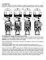
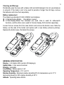
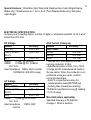
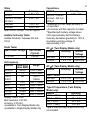
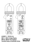
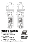
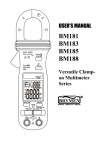
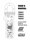
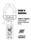
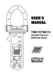
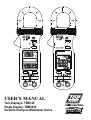
USER'S MANUAL
Twin Displays: TBM126
Single Display: TBM3030
Versatile Clamp-on Multimeter Series
1
1) SAFETY
This manual contains information and warnings that must be followed for operating the
instrument safely and maintaining the instrument in a safe operating condition. If the
instrument is used in a manner not specified by the manufacturer, the protection
provided by the instrument may be impaired.
The meter meets the requirements for double insulation to IEC61010-2-032, EN610102-032, UL61010B-2-032, IEC61010-1 2nd Ed., EN61010-1 2nd Ed., UL61010-1 2nd
Ed.:
Category III 600 Volts ac and dc.
PER IEC61010 OVERVOLTAGE INSTALLATION CATEGORY
OVERVOLTAGE CATEGORY II
Equipment of OVERVOLTAGE CATEGORY II is energy-consuming equipment to be
supplied from the fixed installation.
Note – Examples include household, office, and laboratory appliances.
OVERVOLTAGE CATEGORY III
Equipment of OVERVOLTAGE CATEGORY III is equipment in fixed installations.
Note – Examples include switches in the fixed installation and some equipment for
industrial use with permanent connection to the fixed installation.
OVERVOLTAGE CATEGORY IV
Equipment of OVERVOLTAGE CATEGORY IV is for use at the origin of the
installation. Note – Examples include electricity meters and primary over-current
protection equipment.
TERMS IN THIS MANUAL
WARNING identifies conditions and actions that could result in serious injury or even
death to the user.
CAUTION identifies conditions and actions that could cause damage or malfunction
in the instrument.
2
WARNING
To reduce the risk of fire or electric shock, do not expose this product to rain or
moisture. The meter is intended only for indoor use.
To avoid electrical shock hazard, observe the proper safety precautions when working
with voltages above 60 VDC or 30 VAC rms. These voltage levels pose a potential
shock hazard to the user. Before and after hazardous voltage measurements, test the
voltage function on a known source such as line voltage to determine proper meter
functioning.
Keep your hands/fingers behind the hand/finger barriers (of the meter and the test
leads) that indicate the limits of safe access of the hand-held part during measurement.
Inspect test leads, connectors, and probes for damaged insulation or exposed metal
before using the instrument. If any defects are found, replace them immediately.
This Clamp-on meter is designed to apply around or remove from uninsulated
hazardous live conductors. But still, individual protective equipment must be used if
hazardous live parts in the installation where measurement is to be carried out could
be accessible.
CAUTION
Disconnect the test leads from the test points before changing meter functions.
INTERNATIONAL ELECTRICAL SYMBOLS
!
Caution ! Refer to the explanation in this Manual
Caution ! Risk of electric shock
Earth (Ground)
Double Insulation or Reinforced insulation
Fuse
AC--Alternating Current
DC--Direct Current
Application around and removal from hazardous live conductors is permitted
2) CENELEC Directives
The instruments conform to CENELEC Low-voltage directive 73/23/EEC and
Electromagnetic compatibility directive 89/336/EEC
3) PRODUCT DESCRIPTION
This user's manual uses only representative model(s) for illustrations. Please refer
specification details for function availability to each model.
3
1) Transformer Clamp Jaw for AC current magnetic field pick up
2) Hand/Finger Barrier to indicate the limits of safe access of the meter during
measurement
3) Push-buttons for special functions & features. Also as power ON/OFF buttons for
ACA function in Twin Display Models
4) Push-buttons for special functions & features on Slide-switch Selector functions
5) Input Jack for all functions EXCEPT non-invasive ACA current function
6) Common (Ground reference) Input Jack for all functions EXCEPT non-invasive
ACA current function
7) Slide-switch Selector to turn the power ON/OFF and Select a function
8) 3-3/4 digits 4000 counts LCD display(s)
9) Jaw trigger for opening the transformer clamp jaw
10) Jaw center Indicators, at where best ACA accuracy is specified
11) Jaw marking lines for ACA position error indication
4
4) OPERATION
CAUTION: Before and after hazardous voltage measurements, test the voltage
function on a known source such as line voltage to determine proper meter functioning.
DC Voltage, AC Voltage, Hz Frequency functions
Set slide-switch to Voltage function position(s). Inputs are made through the test leads
terminals. For Twin Display Models, slide-switch on defaults at AC voltage. Press
SELECT button momentarily to select DC voltage.
Press the Hz button momentarily to activate Hz Frequency function in the following
slide-switch functions:
Single Display Models: DCV & ACV via the test leads; ACA via the clamp jaw
Twin Display Models: DCV, ACV, DCµA & ACµA via the test leads (not available to
ACA)
Note: DC 400.0mV range is designed with 1000MΩ high input impedance for least
current drain in measuring small signals, and can cope better with most commercially
available voltage output transducers/adapters. The non-zero display reading is normal
when the meter inputs are open circuit, which will not affect actual measurement
accuracy. The meter will show close to zero readings when the inputs are shorted.
Open input is actually a floating condition, which is not a zero-volt-input condition.
5
Note: The Hz trigger level is determined by the selected function-range from where
the Hz function is activated. In ACV function:
Activating the Hz function during significant measurements can get the most
appropriate trigger level to avoid electrical noises in most cases. Electrical noise may
cause unstable Hz reading.
Activating the Hz function at AC 4.000V range (before making significant
measurements) can get lower trigger level (higher sensitivity). Hz reading may show
zero when the sensitivity is insufficient.
CAUTION
Using Resistance, Continuity, Diode or Capacitance function in a live circuit will
produce false results and may damage the instrument. In many cases the suspected
component must be disconnected from the circuit to obtain an accurate measurement
reading.
6
Ω Resistance, and Continuity functions
Inputs are made through the test leads terminals. Slide-switch on defaults at Ω. Press
SELECT button momentarily to select Continuity function which is convenient for
checking wiring connections and operation of switches. A continuous beep tone
indicates a complete wire.
Diode test function
Inputs are made through the test leads terminals. Slide-switch on defaults at Ω. Press
Diode test function. Normal forward
SELECT button momentarily 2 times to select
voltage drop (forward biased) for a good silicon diode is between 0.400V to 0.900V. A
reading higher than that indicates a leaky diode (defective). A zero reading indicates a
shorted diode (defective). An OL indicates an open diode (defective). Reverse the test
leads connections (reverse biased) across the diode. The digital display shows OL if
the diode is good. Any other readings indicate the diode is resistive or shorted
(defective).
Capacitance function
Inputs are made through the test leads terminals. Slide-switch on defaults at Ω. Press
Capacitance function.
SELECT button momentarily 3 times to select
Note: (applies to Model TBM3030 only)
Relative zero mode can be used to zero out the parasitic capacitance of the leads
and the internal protection circuitry of the meter when measuring low capacitance in
the order of Pico Farad (pF).
CAUTION
Discharge capacitors before making any measurements. Large value capacitors
should be discharged through an appropriate resistance load
ACA function
Inputs are made through the clamp jaws for non-invasive ACA current measurements.
For Single Display Models, set the slide-switch to select the ACA function.
For dual inputs Twin Display Models, press the OFF push button momentarily to power
on and off the separate ACA function display. The HOLD push button can also be used
as the ACA function power on hotkey. This twin display ACA function can be used
simultaneously with the voltage or any other slide-switch functions when making
measurements.
7
CAUTION (Application and removal of the Clamp-on meter)
For non-invasive ACA current measurements, press the jaw trigger and clamp the jaws
around only one single conductor of a circuit for load current measurement. Make sure
the jaws are completely closed, or else it will introduce measurement errors. Enclosing
more than one conductor of a circuit will result in differential current (like identifying
leakage current) measurement. Locate the conductor(s) at the Jaws center as much as
possible to get the best measuring accuracy. For removal, press the jaw trigger and
remove the jaws from the conductor(s).
Adjacent current-carrying devices such as transformers, motors and conductor wires
will affect measurement accuracy. Keep the jaws away from them as much as possible
to minimize influence.
8
Temperature function (Twin Display Model only)
Be sure to insert the banana plug type-K temperature bead probe Bkp60 with correct
polarities. Slide-switch on defaults at degree C (Celsius). Press SELECT button
momentarily to select degree F (Fahrenheit). You can also use a plug adapter Bkb32
(Optional purchase) with banana pins to type-K socket to adapt other type-K standard
mini plug temperature probes.
µA Current function (Twin Display Model only)
Inputs are made through the test leads terminals. Slide-switch on defaults at DC. Press
SELECT button momentarily to select AC.
Application notes:
The DCµA function is designed especially for HVAC/R flame sensor applications. The
0.1µA resolution is useful for identifying the minute current changes in flame detector
9
applications. Flame signal current check should indicate steady flame signal of at
least 2µA for a rectification type, or 1.5µA for an ultraviolet type (8µA for self checking
systems). If a flame signal current with inadequate strength or fluctuation beyond 10%,
check the following to avoid the risk of unwanted flame relay dropout :
1-1) For gas or oil flames (Minipeeper):
Low supply voltage
Detector location
Defective detector wiring
Dirty viewing windows
Faulty Minipeeper
1-2) For oil flames (Photocell):
Detector location & wiring
Smoky flame or poorly adjusted air shutter
Faulty Photocell
Temperature over 165 F (74 C) at photocell
1-3) For gas flames (Flame Rod):
Ignition interference (A flame signal current difference with the ignition both on and
off greater than 0.5µA indicates the presence of ignition interference)
Insufficient ground (must be at least 4 times the detector area)
Flame lifting off burner head (ground), or not continuously in contact with the flame
rod
Temperature in excess of 600 oF (316 oC) at the flame electrode insulator causing
short to ground.
HOLD
The hold feature freezes the display for later view. Press the HOLD
momentarily toggles to hold mode in the following function(s):
Single Display Models: All functions
Twin Display Models: Upper display ACA function
button
MAX
The max feature compares and displays the measured maximum value as fast as
30ms with auto-ranging capability. Press the MAX button for 1 second or more
toggles to max feature in the following function(s):
Single Display Models: DCV, ACV & ACA functions
Twin Display Models: Upper display ACA function
10
Relative zero mode (Single Display Models only)
Relative zero mode allows the user to offset the meter consecutive measurements
with the displaying reading as the reference value. The display will now show readings
relative to the stored reference value. That is, display = reading - stored value. Press
the button momentarily toggles to relative zero mode.
Auto-ranging
Where there is more than one measuring range under a selected meter function, the
LCD annunciator “a” turns on. The meter will automatically switch to the best resolution
range when making measurements. No manual ranging selection is required.
Auto Power Off (APO)
When the meter is on, the Auto Power Off (APO) feature will switch the meter into a
sleep mode automatically to extend battery life after approximately 30 minutes of no
slide-switch nor push button operations. To wake up the meter from APO, press the
buttons momentarily or set the slide-switch to the OFF position and then slide back on
again. Always set the slide-switch to the OFF position manually when the meter is not
in use.
5) MAINTENANCE
WARNING
To avoid electrical shock, disconnect the meter from any circuit, remove the test leads
from the input jacks and turn OFF the meter before opening the case. Do not operate
with open case.
Trouble Shooting
If the instrument fails to operate, check batteries and test leads etc., and replace as
necessary. Double check operating procedure as described in this user’s manual.
If the instrument voltage-resistance input terminal has subjected to high voltage
transient (caused by lightning or switching surge to the system) by accident or
abnormal conditions of operation, the series fusible resistors will be blown off (become
high impedance) like fuses to protect the user and the instrument. Most measuring
functions through this terminal will then be open circuit. The series fusible resistors and
the spark gaps should then be replaced by qualified technician. Refer to the LIMITED
WARRANTY section for obtaining warranty or repairing service.
11
Cleaning and Storage
Periodically wipe the case with a damp cloth and mild detergent; do not use abrasives
or solvents. If the meter is not to be used for periods of longer than 60 days, remove
the batteries and store them separately.
Battery replacement
The meters use standard 3V IEC-CR2032 coin batteries
In Signle Display Model: One battery is used.
In Twin Display Model: Two batteries are used. One is used for slide-switch
functions, and the other one is used for the twin display ACA function separately.
Loosen the two screws from the case bottom and remove the bottom case. Slide the
battery out the side of the holder and replace with a new battery (observe polarity).
Replace the bottom case. Re-fasten the screws.
GENERAL SPECIFICATION
Display : 3-3/4 digits 4000 counts LCD display(s)
Update Rate : 3 per second nominal
Polarity : Automatic
Low Battery : Below approx. 2.4V
Operating Temperature : 0°C to 40°C
Relative Humidity : Maximum relative humidity 80% for temperature up to 31°C
decreasing linearly to 50% relative humidity at 40°C
Altitude : Operating below 2000m
12
-20oC
60oC,
Storage Temperature :
to
< 80% R.H. (with battery removed)
Temperature Coefficient : nominal 0.15 x (specified accuracy)/oC @(0oC ~ 18oC or
28oC ~ 40oC), or otherwise specified
Sensing : Average sensing
Overload Protections :
ACA Clamp-on jaws : AC 600A rms continuous
+/µA & COM terminals: 600VDC/VAC rms
Transient protection : 6.5kV (1.2/50µs surge) for all models
Safety : Meets IEC61010-2-032, EN61010-2-032, UL61010B-2-032, IEC61010-1 2nd
Ed., EN61010-1 2nd Ed., UL61010-1 2nd Ed.
Measurement Category : III 600 Volts ac & dc
Pollution degree : 2
E.M.C. : Meets EN61326 (1997, 1998/A1), EN61000-4-2 (1995, 2000/A2), and
EN61000-4-3 (2002)
In an RF field of 3V/m:
Capacitance function is not specified
µA function (Twin Display Model only) :
Total Accuracy = Specified Accuracy + 65 digits
Other function ranges:
Total Accuracy = Specified Accuracy + 45 digits
Performance above 3V/m is not specified
Power Supply : 3V coin battery IEC-CR2032
One battery for Single Display Models;
Two batteries for Twin Display Models
Power Consumption : 2.8mA typical except that 3.3mA typical for ACA function
APO Timing : Idle for 30 minutes
APO Consumption : 5µA typical on all model functions except that 40µA typical on
voltage function of Models 127M & 128M
Dimension : L190mm X W63mm X H32mm
Weight : 139 gm approx
Jaw opening & Conductor diameter : 26mm max
Accessories : Test leads (pair), battery(ies) installed, user's manual, & soft carrying
pouch; Banana plug type-K bead probe Bkp60 x 1 (Twin Display Model only)
Optional Accessories : Banana pins to type-K socket plug adapter Bkb32 (Twin
Display Model only)
13
Special Features : 30ms Max Hold; Data Hold; Relative Zero mode (Single Display
Model only); Simultaneous A+V, A+Ω, A+oC (Twin Display Model only); Slim jaws;
Light Weight
ELECTRICAL SPECIFICATION
Accuracy is ±(% reading digits + number of digits) or otherwise specified, at 23oC ±5oC
& less than 75% R.H.
DC Voltage
RANGE
Accuracy
400.0 mV
0.3% + 4d
4.000V, 40.00V,
0.5% + 3d
400.0V
600V
1.0% + 4d
NMRR : >50dB @ 50/60Hz
CMRR : >120dB @ DC, 50/60Hz,
Rs=1kΩ
Input Impedance : 10MΩ, 30pF nominal
(1000MΩ for 400.0mV range)
AC Voltage
RANGE
Accuracy
50Hz ~ 500Hz
4.000V, 40.00V,
1.5% + 5d
400.0V
600V
2.0% + 5d
CMRR : >60dB @ DC to 60Hz,
Rs=1kΩ
Input Impedance : 10MΩ, 30pF
nominal
ACA Current (Clamp-on)
RANGE
Accuracy 1) 2) 3)
50Hz / 60Hz
40.00A
1.5% +8d
400.0A
1.5% +8d
600A
1.5% + 8d
1)Induced error from adjacent currentcarrying conductor: 0.05/A
2)Specified accuracy is from 1% to 100%
of range and for measurements made at
the jaw center. When the conductor is not
positioned at the jaw center, position
errors introduced are:
Add 2% to specified accuracy for
measurements made BEYOND jaw
marking lines (toward jaw opening)
3)Add 8d to specified accuracy @ reading
< 10% of range
Max Hold (where applicable)
Specified accuracy ± 50 digits for
changes > 25ms in duration
14
Ohms
RANGE
Accuracy
0.8% + 8d
400.0Ω
0.6% + 4d
4.000kΩ, 40.00kΩ,
400.0kΩ
1.0% + 4d
4.000MΩ
2.0% + 4d
40.00MΩ
Open Circuit Voltage : 0.4VDC typical
Audible Continuity Tester
Audible threshold : between 5Ω and
120Ω.
Diode Tester
Open Circuit Voltage
< 1.6 VDC
Test Current
(Typical)
0.25mA
Hz Frequency
Function
Sensitivity
Range
(Sine RMS)
400.0mV
350mV
10Hz ~ 2kHz
4.000V
1V
10Hz ~ 5kHz
4.000V,
32V
10Hz ~
40.00V
100kHz
400.0V
100V
10Hz ~ 10kHz
600V
500V
10Hz ~ 5kHz
400.0µA 1)
500µA 10Hz ~ 30kHz
2000µA 1)
500µA 10Hz ~ 30kHz
400.0A 2)
60A
40Hz ~ 400Hz
Display counts: 5000
Best resolution: 0.001Hz
Accuracy: 0.5%+4d
1)Available to Twin Display Model only
2)Available to Single Display Model only
Capacitance
Accuracy 2) 3)
RANGE 1)
3.5% + 6d
500.0nF, 5.000µF,
50.00µF, 500.0µF,
3000µF
1)Additional 50.00nF range accuracy is
not specified
2)Accuracies with film capacitor or better
3)Specified with battery voltage above
2.8V (approximately half full battery).
Accuracy decreases gradually to 12% at
low battery warning voltage of
approximately 2.4V
DC µA (Twin Display Model only)
RANGE
Accuracy
Burden
Voltage
2.0% + 4d 2.8mV/µA
400.0µA
1.2% + 3d 2.8mV/µA
2000µA
AC µA (Twin Display Model only)
RANGE
Accuracy
Burden
Voltage
50Hz ~ 500Hz
2.0% + 5d 2.8mV/µA
400.0µA
1.5% + 5d 2.8mV/µA
2000µA
Type-K Temperature (Twin Display
Model only)
RANGE
Accuracy
-20oC ~ 300oC
2% + 3oC
301oC ~ 537oC
3% + 3 oC
-4oF ~ 572oF
2% + 6oF
573oF ~ 999oF
3% + 6oF
Type-K thermocouple range & accuracy
not included
LIMITED WARRANTY
BRYMEN warrants to the original product purchaser that each product it manufactures
will be free from defects in material and workmanship under normal use and service
within a period of one year from the date of purchase. BRYMEN's warranty does not
apply to accessories, fuses, fusible resistors, spark gaps, batteries or any product
which, in BRYMEN's opinion, has been misused, altered, neglected, or damaged by
accident or abnormal conditions of operation or handling.
To obtain warranty service, contact your nearest BRYMEN authorized agent or send
the product, with proof of purchase and description of the difficulty, postage and
insurance prepaid, to BRYMEN TECHNOLOGY CORPORATION. BRYMEN assumes
no risk for damage in transit. BRYMEN will, at its option, repair or replace the
defective product free of charge. However, if BRYMEN determines that the failure was
caused by misused, altered, neglected, or damaged by accident or abnormal
conditions of operation or handling, you will be billed for the repair.
THIS WARRANTY IS EXCLUSIVE AND IS IN LIEU OF ALL OTHER WARRANTIES,
EXPRESSED OR IMPLIED, INCLUDING BUT NOT LIMITED TO ANY IMPLIED
WARRANTY OR MERCHANTABILITY OR FITNESS FOR A PARTICULAR
PURPOSE OR USE. BRYMEN WILL NOT BE LIABLE FOR ANY SPECIAL,
INDIRECT, INCIDENTAL OR CONSEQUENTIAL DAMAGES.
BRYMEN TECHNOLOGY CORPORATION
TEL:+886 2 2226 3396
FAX:+886 2 2225 0025
http://www.brymen.com
PRINTED ON RECYCLABLE PAPER, PLEASE RECYCLE
COPYRIGHT © MMVIII Btc,
ALL RIGHTS RESERVED
P/N: 7M1C-0921-A007
PRINTED IN TAIWAN