1
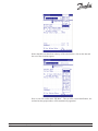
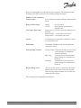
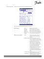
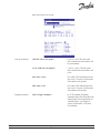
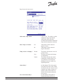
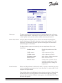
Refrigeration and Air Conditioning Controls User’s manual Degree Master Controller in AKC 55 Systems ADAP-KOOL REFRIGERATION AND AIR CONDITIONING Table of Contents Introduction Configuring the host AKC 55 for Degree Master Setting up a circuit Defrost configuration Anti-sweat heaters Lighting schedules Alarm delays Alarm actions and trip levels Alarm types Sensor failure alarms Locate and Initialize procedures Wink p. 3 pp. 5-6 pp. 5-16 pp. 9-11 p. 12 p. 12 pp. 13-14 p. 14 p. 15 p. 15 pp. 15-16 p. 16 Using the Degree Master in an AKC 55 System Degree Master status screen Software version Navigational icons Schedules Defrost map Service screen Auto, Manual On, and Manual Off Alarm override Dual temp mode New Case State pp. 17-22 p. 17-19 p. 17 p. 19 p. 19 pp. 20-21 p. 20 p. 21 p. 21 p. 21 pp. 21-22 Degree Master in AKC 55 Systems 02/02.1 084R9897 2 RS.8B.F1.22 Introduction The Degree Master is a Hill PHOENIX stand-alone controller for refrigerated cases and boxes in supermarkets. In addition to stand-alone operation, Degree Masters can function as nodes in the input-output network of an AKC 55 supermarket control and monitoring system. The Degree Master is powered by the fixture in which it is installed by the case manufacturer. In addition to the load center and an on-case display, the installation may include outboard add-on modules for defrost and antisweat heaters. Outputs The Degree Master Load Center can support three kinds of outputs: (1) one solenoid valve or compressor; (2) lights; (3) fans or defrost. Inputs There can be up to five sensor inputs. Display and wireless remote Echelon® communications Further information The Degree Master has a local display that shows sensor values and settings and that can be used to program some functions. A user can fully interrogate and program the unit using its wireless handheld remote control. When used in an AKC 55 system, the Degree Master can be completely configured, and all settings and values observed, at the AKC 55 display or on a connected PC. The Degree Master, like other devices on an AKC 55’s IO network, is Echelon® compatible. Because the Degree Master is an FTT device, an FTT to TP78 bridge is needed when connecting it to an AKC 55 IO network. The remainder of this manual deals with configuration and use of the Degree Master in an AKC 55 supermarket control and monitoring system. For complete information about Degree Master display and handheld functions, refer to the Degree Master handbook supplied by Hill PHOENIX. Degree Master in AKC 55 Systems 02/02.1 084R9897 3 RS.8B.F1.22 Degree Master in AKC 55 Systems 02/02.1 084R9897 4 RS.8B.F1.22 Configuring the host AKC 55 for Degree Master [Note: In the remainder of this manual, some familiarity with the AKC 55, particularly with navigation, is assumed. For a refresher, refer to Chapter 4 (introduction) and the first part of section 4-1, and the introduction and section 5-1 of the AKC 55 System User’s Manual. Those portions of the manual contain information on navigation and making changes both at the AKC 55 keypad and display or at your PC. The following instructions assume that you are doing the configuration from a PC.] The manual is available electronically from the literature library at www.danfoss.com. ] Locate and Init will be needed After initial configuration, a Degree Master needs to be put through the Locate process, described at the end of this section on page 16. The Locate process only needs to be done once when a Degree Master is connected to the system After any change in configuration, whether in the configuration screens or the settings screens, the Init procedure must be used before the changes will take effect. The procedure is described at the end of this section on page 16. To begin configuration of a circuit with Degree Master controllers, select Evaporators from the Configure Rack menu, then increment the number of circuits. Next, under Type for the new circuit, left click on the field contents (by default “AKC 55”) , and a selection box appears: With the selection box open, click on DEG MASTER and right click or press ENTER. Then click on >Setup< in the rightmost column for your new circuit. You can subsequently change the configuration of the circuit by using >Setup<. Setting up a circuit Degree Master in AKC 55 Systems When the circuit setup screen appears, choose the type of case. Let’s assume that we are configuring a single deck meat case, so for fixture type we select “single deck. For the second line, “fixture name,” we want to select “meat case,” but all we see in the selection box is this: 02/02.1 084R9897 5 RS.8B.F1.22 Notice that there are three dots at the top of the selection box. click on the dots and the rest of the selections appear: Now we can click on the name “SD Meat.” The rest of the circuit identification, the rack and suction group number, will be automatically appended. Degree Master in AKC 55 Systems 02/02.1 084R9897 6 RS.8B.F1.22 Now proceed through the screen and answer the questions. The questions and the meanings of the choices follow for the remaining configuration pages. Number of case controllers on this circuit? Refrig Control Type? (0 to 15) Enter the number of Degree Masters on the circuit. NONE CYCLE Valve open when relay? No case control. Degree Master is controlling a solenoid valve. [appears only if CYCLE is selected for the previous question] Energized OFF - for normally closed valves Energized ON - for nomally open valves Cut in? The discharge air temperature at which the controller will open the valve. Dead band? The number of degrees below cut-in at which the valve will be closed. Line-up Temp Control? Average Temp Control will be based on the average of the discharge air temperature sensors in the lineup. Max Temp Control will be based on the maximum discharge air temperature in the lineup. Min Temp Control will be based on the minimum discharge air temperature in the lineup. RO for Refrig Valve? (Yes, No) A relay output is created for each Degree Master on the circuit. Answer Yes to the question when the refrigeration solenoid valve is at the rack rather than at the fixture. The second page of configuration looks like this: Degree Master in AKC 55 Systems 02/02.1 084R9897 7 RS.8B.F1.22 The Degree Master has five channels for universal analog inputs. Not all sensors need be present. The case manufacturer usually supplies a list of the sensors installed and their channels. A given sensor channel can serve more than one purpose; for example, a discharge air temperature sensor can also serve as defrost termination sensor. In that case, the same channel number would be entered opposite both names. Sensor types are as follows: TP1 TP2 DIG A temperature sensor, part no. C26001000 A temperature sensor, part no. 084N3016 The input is from dry contacts such as for a door or for a defrost termination thermostat. A BAT product temperature sensor made by Elm Controls Elm Fan cycle control? Cycle Normal Fan cycle temperature? Use Fan/Defr relay as? Fans will cycle on Evap Out temperature. Fixture fans will not cycle. (-99.9° to 99.9°(Appears only when Cycle is selected for the previous question) When Evap Out temperature is greater than Fan cycle temperatuare, fans will be turned off. Fans Defrost The Fan/Defrost relay will operate on fan logic. The Fan/Defrost. relay will operate on defrost logic. Page down for the next screen of settings: Degree Master in AKC 55 Systems 02/02.1 084R9897 8 RS.8B.F1.22 ` Defrost configuration This screen contains all defrost configuration questions. The questions, and their possible answers, are as follows: Degree Master in AKC 55 Systems Defrost type? None Electric Hot Gas Warm Liq Reverse Air Passive Defrost term. method? Time No defrost is controlled. The circuit has electric defrost. The circuit has hot gas defrost. The circuit has warm liquid defrost. The circuit has reverse air defrost. The circuit has time off defrost. Defrost will terminate when the maximum defrost time has been reached. Defrost Temp Defrost will terminate when the defrost temperature sensor reaches a value set in the next answer unless the maximum defrost time is reached at a lower temperature. Time settings have priority. If the fixture reaches termination temperature before minimum time has expired, the defrost still must complete minimum time. If termination temperature has not been reached before maximum time has expired, the defrost will terminate on time.] Contact Closed Termination depends on closure of a defrost termination thermostat. Contact Open Termination depends on opening of a defrost termination thermostat. 02/02.1 084R9897 9 RS.8B.F1.22 Defrost term. temp? (-99.9 to 99.9) (appears only when Defrost Temp is selected as the termination method) Defrost Time Min Max Degree Master in AKC 55 Systems (0-120 minutes) The minimum time for each defrost. (0-120 minutes) The maximum time for each defrost. Num. of defrosts per day? The number of defrosts that will be initiated per day, from 0 to 24. The first defrost will initiate at the time specified in the next answer. Remaining defrosts will be at equally spaced intervals during the hours remaining after the first defrost until midnight each day. Defrost start time? The time for the first defrost to begin. Coordinated defrost? When multiple Degree Masters are operating on a circuit, they will defrost at the same time. Refrigeration will not resume for any fixture until all have finished defrosting. Drip down delay? (0-999 minutes)The number of minutes that refrigeration will remain off after defrost termination to allow for liquid to drain from the evaporator.. Valve during defrost? (Closed, Open) The state of the refrigeration solenoid valve during defrost Fans during defrost? (Normal, Off) The state of controlled fixture’s fans during defrost. Lights during defrost? (Normal, Off) The state of controlled fixture lights during defrost. ASH during defrost? (Normal, Off) The state of controlled anti-sweat heaters during defrost. 02/02.1 084R9897 10 RS.8B.F1.22 Degree Master in AKC 55 Systems Fan start temp after def? (-99.9° to 99.9°) The defrost termination temperature sensor temperature at which the controlled fixture’s fans will begin to operate after defrost termination. Fan start time after def? (0-999 minutes) The maximum time that will elapse after defrost before fans start, regardless of temperature. Post defrost alarm delay? (0-999 minutes) The time that must elapse before fixture alarms will begin operating after termination of defrost. Alarm counters will remain at zero until this time elapses. 02/02.1 084R9897 11 RS.8B.F1.22 Page down to the next screen: Anti-sweat heaters Lighting schedules Degree Master in AKC 55 Systems ASH ON above dew point? (-100° to +100°) The dew point above which anti-sweat heaters will be on constantly. Cycle ASH above dewpoint? (-100° to +100°) The dew point above which anti-sweat heaters will cycle. Max. duty cycle? (0 to 100%) The maximum percentage of any 7 second cycle that antisweat heaters will operate. Min. duty cycle? (0 to 100%) The minimum percentage of any 7 second cycle that antisweat heaters will operate. Num of light schedules? (0-7) The number of lighting schedules that will be entered for the fixture lights. For an explanation of schedule entries, see Chapter 4 section 4 of the AKC 55 System User Manual. 02/02.1 084R9897 12 RS.8B.F1.22 Page down to the next screen: Offset med. temp. mode? Show Temp in Celsius? (-40° to +40°) The offset by which temperature target setpoint and alarm limits will be raised for operation in the medium temperature range in dual temperature operation. Yes No Temp to show on display? Product Case Control Alarm delay? Case clean alarm delay? Degree Master in AKC 55 Systems 02/02.1 Temperatures will be shown in degrees Celsius. Temperatures will be shown in degrees Fahrenheit. The display will show the value of a product sensor. The diplay will show the discharge air temperature. The display will show the control temperature, whether lineup average, minimum, or maximum (depending on answer to earlier configuration question. (0-999 minutes) This is the general time limit for the four sensor alarms described in the next screen. It is not returned to the factory default (30 minutes) when sensor alarms are deleted. (See discussion about the next screen). (0-999 minutes) The number of minutes that alarms will be sus084R9897 13 RS.8B.F1.22 pended when case cleaning is initiated with the remote control or in the service screen. Alarms Alarm actions and trip levels Door alarm delay? (0-999 minutes) The number of minutes a door can remain open before an alarm is generated. ASH During High Alarm? (On, Off) State of anti-sweat heaters during high temperature alarm conditions. Lite During High Alarm? (On, Off) State of lights during high temperature alarm conditions. Before we discuss the next screen, reached by paging down, it will be useful to review the various alarm levels that can be assigned to any alarm in an AKC 55 system. There are four alarm levels that appear in the selection box in the center: Disabled The alarm settings remain configured but alarms will not be generated. Alarms can be reactivated with settings previously configured by selecting Log Only, Normal, or Critical. Log Only Alarms will be logged, but will not be routed to local or remote locations (as specified in the alarm routing screen). Normal Alarms will be generated once and routed to all active locations specified in the alarm routing screen. Critical Alarms will be generated and routed to all active locations specified in the alarm routing screen. Once a critical alarm trips, it will be sent out repeatedly to active locations at the interval specified for critical alarms in its AKC 55 until either clear or acknowledged. An alarm is clear when its sensor value returns to a non-alarm level. <Delete> The alarm is disabled and the setting (in this case the temperature level only) returned to the factory default (50°)The next screen, which we reach by paging down, concerns alarms. Now page down to the next screen: Degree Master in AKC 55 Systems 02/02.1 084R9897 14 RS.8B.F1.22 Alarm types The upper portion of the screen lists the types of standard alarms that can be generated by a Degree Master. Each can have a trip level from -999.9° to +999.9°. If the <delete> option is used, the value will be returned to the factory default, 50°. Sensor failure alarms A Degree Master can support up to six sensors, each with an associated failure alarm. A failed sensor is one that is shorted or an open circuit, reading 127°or -40° respectively. The same delay (set in the previous screen) applies to sensor failure alarms that applies to other alarms. The Degree Master sensors are installed by the case manufacturer. Their usual locations are: Product sensor Placed in the product area of the fixture. CoilIn sensor At the evaporator coil inlet. Locate Procedure CoilOut sensor At the evaporator coil outlet. Discharge sensor In the primary discharge air stream Return sensor Defrost sensor In the return air stream. Usually on the evaporator coil; but sometimes a single sensor is used for both defrost and discharge air temperatures. When a new Degree Master is added to the AKC 55 system, or when there has been a service replacement, you must use the “Locate Procedure” so that the AKC 55 will recognize the Degree Master. From the Main Menu, select Refrigeration, then select the rack, then Configure Rack, and Board & Points. Select the rightmost icon at the bottom of the screen, which represents Other Controllers. When the menu appears, select DEG MASTER. This is the screen that appears: Degree Master in AKC 55 Systems 02/02.1 084R9897 15 RS.8B.F1.22 Follow this procedure: 1) Enter an address from 1 to 99 that is unique among the Degree Masters in the system. 2) Select Locate and press ENTER or click with your mouse. 3) A message will appear requesting that you press the service pin. 4) You have 10 minutes to go to the particular Degree Master you are working with and depress the service pin. The service pin (or button) is located beneath the upper right corner of the square white label on the Degree Master. 5) Use a pencil (or other instrument that will fit through the access hole) to depress the service button and keep it depressed for five seconds. It will take the AKC 55 from 10 to 15 seconds to complete the location process, after which a message box will appear on the AKC 55 telling you that the process has been successful. This process must be repeated for each new or replacement Degree Master. Activating the service pin from the display After starting the locate procedure from the AKC 55 keypad, it is possible to activate the service pin from the Degree Master’s display. Press and hold both buttons for 3 seconds. When the Degree Master enters the service mode, the display will change to “RS” with an up arrow on the left and a down arrow on the left. Pressing the lower button will now activate the service pin. The down arrow will change to an asterisk as confirmation. Be careful not to press the upper button. Doing so will reset the Degree Master. Initialization After the Locate procedure, Select Init and press ENTER or click with your mouse. The initialization procedure will take about 10-15 seconds. Wink “Wink All Degree Master” is a toggle (first ENTER turns on, second turns OFF) that will cause all the Degree Masters on the network to flash their node numbers repeatedly. If a unit does not wink its number, test its function with the handheld remote control. If the unit is functioning to control the fixture, troubleshoot its network connection and addressing. Degree Master in AKC 55 Systems 02/02.1 084R9897 16 RS.8B.F1.22 Using the Degree Master in an AKC 55 System [Note: In the remainder of this manual, some familiarity with the AKC 55, particularly with navigation, is assumed. For a refresher, refer tto Chapter 4 (introduction) and the first part of chapter 4-1, and the introduction and section 5-1 of chapter 5 of the AKC 55 System User’s Manual. Those portions of the manual contain information on navigation and making changes both at the AKC 55 keypad and display or at your PC. The following instructions assume that you are doing the configuration from a PC.[ The manual is available electronically from the literature library at www.danfoss.com. ] Degree Master status screen Software version From the AKC 55 Main Menu, select Refrigeration, then the rack, then Evaporators, and finally the Degree Master circuit you want to work with. The screen that appears contains current information about the Degree Master‘s status: At the top right of the main body of the screen is the version of software running in the Degree Master, in the illustrated screen, version DM010110. In the main body of the screen, the meanings of the fields and their contents are as follows. All possible sensors are listed; only those configured will have readings. Unconfigured sensors will have an asterisk in the value field. Status: Degree Master in AKC 55 Systems The field gives the current operating state of the fixture: Refrigeration The fixture is operating with its current Degree Master settings. Defrosting Defrost is underway. Refrigeration is off. Drip Down Defrost has terminated. Refrigeration is off pending completion of the drip down period configured. 02/02.1 084R9897 17 RS.8B.F1.22 Status (cont’d) Fan Delay Defrost has terminated. Refrigeration is on. Fans are off pending completion of the fan delay time. Case Cleaning The fixture is shut down for cleaning. Case Off The fixture has been turned off by means of the service screen. Degree Master in AKC 55 Systems Case: The temperature of the sensor being used for control, as selected during configuration. Target: The target temperature set during configuration. Product: Evap In: Product sensor temperature. Evaporator inlet sensor temperature. Evap Out: Evaporator outlet sensor temperature. Suprht: Calculated superheat. Disch: Discharge air sensor temperature. Return: Return air sensor temperature. Def Term: Dedfrost termination sensor temperature. Dewpoint: Dewpoint as calculated by the AKC 55. Vlv Duty: Current valve duty percentage calculated by the Degree Master. ASH Duty: Current ASH duty percentage calculated by Degree Master. Antisweat: (On, Off) State of anti-sweat heaters. Lights: (On, Off) State of fixture lights. Fans: (On, Off) State of fixture fans. Defrost: (On, Off) Stateof fixture defrost. Refrig: (On, Off) State of refrigeration in 02/02.1 084R9897 18 RS.8B.F1.22 the fixture. Def Term: (On, Off) State of defrost termination thermostat. Door: (Open, Closed) State of door switch. Navigational Icons There are six navigational icons at the bottom of the screen. The main evaporator status icon leads to the screen we have just discussed. In this manual we will cover screens brought up by two of the other icons: Schedules (the clock icon) and Service (the person with tookbox and wrench) ; the other icons (User-defined screen, Alarms, and Authorization) are covered in the AKC 55 System User Manual. Schedules Select the clock icon at the bottom of any screen for a circuit and you will be taken to that circuit’s schedules screen. For a Degree Master, the screen looks like this: The fields and the meaning of their contents is as follows: Degree Master in AKC 55 Systems Defrosts per day: The number of defrosts per day chosen during configuration. Start: Start time for the first defrost. Min: Minimum defrost time in minutes. Max: Maximum defrost time in minutes. Last Def Dur: Duration of the most recently terminated defrost. Last Def Time: Time that the last defrost was initiated. 02/02.1 084R9897 19 RS.8B.F1.22 Defrost map A related screen is the Defrost Map, which is reachable from its icon at the bottom of the evaporator menmu screen (evaporator overview screen) that lists all the circuits in the group. The defrost map shows graphically the defrosts of all the defrosts in the group and when they occur. Here’s the screen for the group we’ve been working with: Service screen Selecting the service icon (a person with a tool kit and wrench) brings up the servcie screen. The fields and the meaning of their contents are as follows: Degree Master in AKC 55 Systems 02/02.1 084R9897 20 RS.8B.F1.22 Status Auto, Manual On, and Manual Off See the list starting on page 17. Fans, Lights, Defrost, Antisweat, and Vlv Duty can be set to any of three operational states in this screen. The states are: Auto The device will operate based on the output of the Degree Master. Manual On Degree Master control is overridden, and the device will remain On until restored to Auto by an authorized person using this screen. Manual Off Degree Master control is overridden, and the device will remain Off until restored to Auto by an authorized person using this screen. Other fields on the screen are these: Alarm Override: Dual Temp Mode New Case State This field is used to toggle the operation of the case between low temperature and medium temperature. The New Case State field is used to put the fixture into certain specific serviceoriented override states, or to return it to normal operation. The settings are: None Normal Operation Degree Master in AKC 55 Systems Alarms from the case can be overridden for a user-specified length of time by entering a number of minutes in this field. No alarms will be generated until the time expires. The fixture will operate with its normal parameters, subject to any overrides in other screens. Normal Defrost A defrost will be initiated that will terminate according to the normal rules established in configuration. Timed Defrost A defrost will be initiated that will terminate when the maximum defrost time has passed. Case Cleaning All functions will be turned off until restored to operation in this screen. An alarm will be generated after the 02/02.1 084R9897 21 RS.8B.F1.22 case cleaning alarm delay expires before the case is returned to normal operation. Case Off Degree Master in AKC 55 Systems 02/02.1 All case functions will be turned off, and will remain off until restored to operation in this service screen. 084R9897 22 RS.8B.F1.22 Danfoss Inc. Air-Conditioning & Refrigeration Division 7941 Corporate Drive Baltimore, MD 21236-4925 Telephone: 410-931-8250 Fax: 410-931-8256 Direct order fax: 800-948-3123 Danfoss shall not be responsible for any errors in catalogs, brochures, or other printed material. Danfoss reserves the right to alter its products at any time without notice, provided that alterations to products already on order shall not require material changes in specifications previously agreed upon by Danfoss and the Purchaser. All trademarks in this areSystems property of the respective companies. Danfoss and the Danfoss logotype are trademarks of Danfoss A/S. All rightsRS.8B.F1.22 reserved. Degree Master in material AKC 55 02/02.1 084R9897 Copyright 2001 Danfoss Inc. 23 084R9897 RS.8B.F1.22


![RS8CH422 AK2 IO [w-AKC 55] User Manual](http://vs1.manualzilla.com/store/data/005784090_1-938eac098068c47f936e9b0d54a0884d-150x150.png)