1
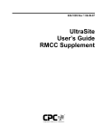
026-1501 Rev 5 3-20-03
Pulse Modulating AntiSweat Control (PMAC II)
Installation and Operation
Manual
1640 Airport Road, Suite 104
Kennesaw, GA 31044
Phone: (770) 425-2724
Fax: (770) 425-9319
ALL RIGHTS RESERVED.
The information contained in this manual has been carefully checked and is believed to be accurate. However, Computer Process Controls, Inc. assumes no responsibility for any inaccuracies that may be contained herein. In no event will
Computer Process Controls, Inc. be liable for any direct, indirect, special, incidental, or consequential damages resulting
from any defect or omission in this manual, even if advised of the possibility of such damages. In the interest of continued
product development, Computer Process Controls, Inc. reserves the right to make improvements to this manual, and the
products described herein, at any time without notice or obligation.
Please Note: This manual covers the PMAC II (P/N 851-1000) family of anti-sweat panels. Information on the PMAC II Solo (P/N 851-1100) anti-sweat controller is contained in P/N 026-1503,
PMAC II Solo Installation and Operation Manual.
Table of Contents
1 OVERVIEW ................................................................................................................................................................... 3
1.1. FEATURES ..................................................................................................................................................................... 3
2 INSTALLATION ........................................................................................................................................................... 4
2.1. LOCATION AND WIRING ...............................................................................................................................................
2.1.1. PMAC II Field Wiring...........................................................................................................................................
2.2. 8DO BOARD CONFIGURATION (STANDARD PMAC II ONLY) .....................................................................................
2.2.1. Digital Outputs......................................................................................................................................................
2.2.2. Fail-Safe Dip Switch .............................................................................................................................................
2.2.3. Network Jumpers...................................................................................................................................................
4
5
6
6
6
6
3 ALARM CONFIGURATION....................................................................................................................................... 8
3.1. THE ALARM CONTACTS ON THE PMAC II TERMINAL STRIP ......................................................................................
3.1.1. Connecting the Alarm Contacts to an Input Board...............................................................................................
3.2. PANEL OVERHEAT ALARMING (ALL MODELS) ............................................................................................................
3.2.1. Overheat Warning.................................................................................................................................................
3.2.2. Panel Overheat Shutdown.....................................................................................................................................
8
8
8
8
8
4 CONFIGURING RMCC, BEC, EINSTEIN AND E2 ................................................................................................ 9
4.1. BEC AND RMCC PAGE LAYOUT ................................................................................................................................. 9
4.2. PROGRAMMING THE BEC............................................................................................................................................. 9
4.2.1. Input Definitions ................................................................................................................................................... 9
4.2.2. Output Definitions................................................................................................................................................. 9
4.2.3. Dewpoint/Humidity Offsets ................................................................................................................................... 9
4.2.4. Outputs Setup ........................................................................................................................................................ 9
4.2.5. Setpoints .............................................................................................................................................................. 10
4.3. PROGRAMMING THE RMCC ....................................................................................................................................... 10
4.3.1. Input Definitions ................................................................................................................................................. 10
4.3.2. Output Definitions............................................................................................................................................... 10
4.3.3. Dewpoint/Humidity Offsets ................................................................................................................................. 10
4.3.4. Anti-Sweat Circuit Setpoints ............................................................................................................................... 11
4.4. PROGRAMMING THE EINSTEIN OR E2......................................................................................................................... 11
4.4.1. Adding an Anti-Sweat Application...................................................................................................................... 12
4.4.2. Configuring Anti-Sweat Applications ................................................................................................................. 12
5 SPARE PARTS LIST .................................................................................................................................................. 16
Einstein RX Controller I&O Manual
Table of Contents • i
1
Overview
The Pulse Modulating Anti-Sweat Control (PMAC II,
P/N 851-1000), shown in Figure 1-1, is a solid state, antisweat heater controller designed to dramatically reduce the
cost of operating anti-sweat heaters on low-temperature
door-type cases found in most supermarkets.
Normally, anti-sweat heaters operate continuously with
no controls, even though 100% operation is required only
when in-store humidity levels are high. A PMAC II provides a means for pulsing power to the heaters based on environmental conditions, so that heaters will be on for less
time during periods where the in-store dewpoint is low.
This reduces operating costs by limiting heater operation,
and increases heater life by limiting heat cycle fatigue since
the heaters are rarely turned off completely.
Depending on the model selected, the PMAC II may
have 16, 20, or 28 heater channels available. Each channel
supports a load of up to 16 amps.
The PMAC II relies on a site controller to control antisweat heater ON percentage based on the in-store dewpoint. The PMAC II panel is compatible with the Building
Environmental Control (BEC), Refrigeration Monitor and
Case Control (RMCC), and Einstein RX or BX, or an E2
site controllers.
Figure 1-1 - PMAC II Detail
The RMCC is capable of controlling up to eight heater
circuits in a single zone, while the BEC allows PMAC IIcontrolled heater circuits to be operated in two separate
zones. Two-zone control allows heaters in higher humidity
zones, such as door cases near prep rooms, to be controlled
separately from other case heaters. An E2 RX or BX can be
configured with up to eight zones.
1.1.
Features
• Full Solid-State Control
• Quiet Operation
• Easily added to existing systems
• Remote communications through the BEC, RMCC,
Einstein RX/BX, or E2 controllers
• Controlled by the store environment (humidity and
temperature)
• Centrally-located panel
• Easy installation
Features
Overview • 3
2
Installation
This section of the manual covers wiring and installation for the PMAC II panels.
2.1.
WARNING: For proper cooling, the door
must be closed at times when unit is in operation.
2.
Provide 120 VAC (15 amp circuit) to the
PMAC II panel through a store circuit breaker. See the layout design in Figure 2-3.
3.
Provide power to the case heaters from the
store circuit breaker panel through the
PMAC II panel terminal strip using #10-12
AWG wire, as shown in Figure 2-4.
Location and Wiring
The following steps provide location and wiring instructions for the PMAC II panel. Figure 2-3 shows this
typical layout. Figure 2-5 shows the PMAC II internal wiring connections.
8.0
”
16.75”
20.0”
17.8”
Mounting
Holes
24.0”
Figure 2-1 - PMAC II Dimensions for the 16 and 20 Channel
8.0
”
Figure 2-3 - Typical Layout
26.0”
27.0”
24.5”
Mounting
Holes
35.0”
Figure 2-2 - PMAC II Dimensions for the 28 Channel
1.
Mount the PMAC II panel in a central location such as a motor or electrical room. The
panel should be where there is good air flow
(not in a closet). Keep a 6-12 inch clearance
on top and bottom for good air flow. The
room’s ambient temperature should always
be below 100° F. Figure 2-1 and Figure 2-2
have the mounting dimensions.
4 • PMAC II I&O Manual
Figure 2-4 - Typical Heater Wiring Layout
026-1501 Rev 5 3-20-03
NOTE: When running power to the case heaters, include the neutral lead in the same conduit as the hot lead to prevent conduit
overheating.
SC-PMAC
#6 +
SC-PMAC
#6 SC-PMAC
#5 +
SC-PMAC
#5 SC-PMAC
#4 +
SC-PMAC
#4 SC-PMAC
#3 +
SC-PMAC
#3 SC-PMAC
#2 +
SC-PMAC
#2 SC-PMAC
#1 +
SC-PMAC
#1 COM 485
white +
COM 485
shield
COM 485
black Alarm
Ground
Alarm
120VAC
HOT
120VAC
Neutral
2.1.1.
Connect the PMAC II panel 8DO board to the
existing RMCC or BEC COM A or COM D
network, as shown in Figure 2-5, using a
Belden #8761 (two-conductor, shielded,
22AWG) or equivalent communication cable.
FUSE
4.
Step 1 Step 2 Step 3
Expansion Ports x 6
PMAC II Field Wiring
Step 1
Step 2
TO EARTH
GROUND
OV
RS 485-
ALARM
RS 485+
ALARM
GROUND
120 HOT
120
NEUTRAL
Figure 2-7 - Wiring Detail for 28 Channel
1.
Provide 120VAC (15 amps circuit) to the
PMAC terminal block through a store circuit
breaker. Wire 120VAC Hot, 120 VAC Neutral, and Ground as indicated by the Step 1
arrows of Figure 2-5 for the 16 Channel, Figure 2-6 for the 20 Channel, and Figure 2-7
for the 28 Channel.
2.
A normally closed alarm contact is provided
on the terminal strip as indicated by the Step
2 arrows of Figure 2-5 for the 16 Channel,
Figure 2-6 for the 20 Channel, and Figure 27 for the 28 Channel.
3.
Step 3 of Figure 2-5 for the 16 Channel, Figure 2-6 for the 20 Channel, and Figure 2-7
for the 28 Channel indicates the terminal
block positions to wire the CPC 485 I/O Network. Polarity must be respected while making these connections.
Step 3
Figure 2-5 - Wiring Detail for 16 Channel
2.1.1.1. Single Channel Expansion Ports
1
Humidity
+12V
Exp A
12VDC +
Exp A
12VDC Exp B
12VDC +
Exp B
12VDC COM 485
white +
COM 485
shield
COM 485
black Hi Temp
Alarm NC
Hi Temp
Alarm NC
Ground
120VAC
Neutral
120VAC
Hot
St
St
2
S
The 20 Channel PMAC has two expansion ports (Figure 2-6), and the 28 Channel PMAC has six single expansion ports (Figure 2-7). These expansion ports can be used
to attach single channel PMACs if desired (P/N 851-1010).
Expansion Ports x 2
Figure 2-6 - Wiring Detail for 20 Channel
Location and Wiring
Installation • 5
2.2.
8DO Board Configuration
(Standard PMAC II Only)
mation to configure the 8DO board to allow
communication between the RMCC, E2 or BEC, the
PMAC II panel, and the case heaters.
Component
Fail-Safe Dip
Switch (S3)
Required
Setting
Action/Notes
Positions 1-4,
UP Position 5,
unused
Provides continuous
12VDC to the PMAC
II relays during network communication loss.
Rotary Dials
(S1)
(S2)
0
1
Jumpers
JU1
JU2
JU3
UP/DOWN
UP/DOWN
UP/DOWN
Addresses the PMAC
II 8DO board as the
#1 8DO board on the
RS-485 Network.
If the PMAC II 8DO
board is the last board
on the RS-485 Network, set all three of
the jumpers UP. If the
board is in the middle
of the RS-485 Network, set the jumpers
DOWN.
Figure 2-8 - 8DO Board
NOTE: Connection of the PMAC II panel
8DO board must meet all networking requirements of the BEC, RMCC, or E2 controllers.
Table 2-1 defines the proper settings for the
PMAC II 8DO board. Refer to the controller’s installation and operation manual for further information.
Network Connection
Connect to
RS-485 Network
Must “daisy-chain"
with other network
boards.
Table 2-1 - PMAC II 8DO Setup
The 8DO (Digital Output) Expansion Board, supplied
with the PMAC II panel, and shown in Figure 2-8, is used
to connect refrigeration and environmental control components, which must be controlled by digital output, to an RS485 I/O Network. An adjustable dip switch, rotary dials,
and jumpers are used to configure the 8DO board to fit a variety of applications. Table 2-1 provides the required infor-
2.2.1.
Digital Outputs
The 8DO Expansion Board uses eight digital outputs,
which modulate at a programmable frequency regulated by
a signal sent from the controller via the I/O Network.
Each of the eight outputs is designed to drive a solidstate device, and is capable of supplying approximately
150 mA at +12 volts (unregulated). Each output has current
limiting circuitry to prevent damage when short-circuited.
When an output is overloaded, the corresponding LED indicator flashes quickly, indicating current limiting is in effect.
2.2.2.
Fail-Safe Dip Switch
The fail-safe dip switch, S3, allows the user to provide
continuous voltage to the case heaters during network communication loss. The fail-safe dip switches should always
remain in the UP position to ensure voltage is always provided to the case heaters. If the switches are set in the
DOWN position, no voltage will be sent to the heaters during network communication loss.
2.2.3.
Network Jumpers
The network jumpers—JU1, JU2, and JU3—define
whether the PMAC II 8DO board is the first or last board,
or a middle board on the RS-485 communication network.
6 • PMAC II I&O Manual
026-1501 Rev 5 3-20-03
Power Connection
The PMAC II 8DO board requires 24VAC (center tap
ground) from the PMAC II transformer and converts it to
12VDC to drive the PMAC II relays.
Network Connection
RS-485 Network communication is provided through
the network communication connection as shown in Figure 2-8, Table 2-1, and described in the Location and Wiring sections of this manual.
8DO Board Configuration (Standard PMAC II Only)
Installation • 7
3
Alarm Configuration
This section explains the alarm capabilities of the
PMAC II and how to set up alarm annunciation and/or reporting using the panel’s ALARM output contacts.
3.1.
3.2.2.
Panel Overheat Shutdown
If, after the warning level is reached, the temperature
continues to rise above 180°F, another thermal sensor will
open and the unit will completely shut down. The unit will
remain shut down until the temperature returns to a normal
level.
The Alarm Contacts on the
PMAC II Terminal Strip
The terminal strip at the bottom the PMAC II interior
has two terminals labeled ALARM, which are Normally
Closed, and which OPEN whenever certain abnormal system conditions occur.
3.1.1.
Connecting the Alarm Contacts to
an Input Board
You may wish to connect the digital ALARM output
from the PMAC II panel to a digital input on a CPC 16AI
or other input device, so that the status of the PMAC II can
be monitored by the central site controller. Refer to your
site controller’s user manual for information on how to do
this. Set up the ALARM output as a standard digital sensor
that is OPEN during alarm conditions and CLOSED when
the system is functioning normally.
If the ALARM contacts are connected to a point on a
16AI or other input board, you may configure the controller
to generate an alarm or perform some other control function to respond to this alarm condition. Refer to the controller’s user manual for information on how to do this.
3.2.
Panel Overheat Alarming (All
Models)
The PMAC II has a feature that prevents equipment
damage as a result of overheating. When the temperature
inside the panel rises above the warning level (165°F), the
normally closed alarm contact will open. If the temperature
continues to rise and exceeds 180°F, the anti-sweat channels will be shut down.
3.2.1.
Overheat Warning
The "warning level" for the PMAC II panel is 165°F. If
a panel interior temperature above 165°F is reached during
operation, a sensor located on one of the upper heat sinks
will open. In a standard PMAC II panel, this will cause the
ALARM contacts on the terminal strip to be set to OPEN.
8 • PMAC II I&O Manual
026-1501 Rev 5 3-20-03
4
Configuring RMCC,
BEC, Einstein and E2
A BEC, RMCC, Einstein, or E2 is capable of controlling eight anti-sweat heater circuits. BECs allow the eight
heaters to be controlled in two different zones, RMCCs one
zone, and Einstein & E2’s eight zones. Each zone requires
its own dewpoint sensor and setpoint(s). A humidity sensor
and temperature sensor may be used in lieu of a dewpoint
sensor.
The following sections outline the procedure for setting
up anti-sweat control in the BEC, RMCC, Einstein, and E2.
For detailed information on system programming, users
should consult the site controller’s user documentation.
4.1.
BEC and RMCC Page Layout
Each data screen used in anti-sweat setup is shown in
sections to follow. Data ranges for data fields—the information supplied in the help prompt lines—are displayed in
brackets and bold type [-99° - 99°] either at the heading for
the particu-lar field description, or—when a heading does
not exist— within the body of the description. Suggested or
default values for a particular entry are always shown in
brackets and bold type immediately following the data
range [-99° - 99°] [-15.5].
4.2.
Programming the BEC
4.2.1.
Input Definitions
4.2.2.
From the Main Menu, press ’7 2’ to access the Output Definitions screen.
Define 8RO and/or 8DO board and point addresses for
the anti-sweat heater zones. Use the down arrow keys to locate the following outputs: (ANTI-SWT 1 - ANTI-SWT 8).
Refer to P/N 026-1103, Building Environmental Con-trol
I&O Manual, Section 6.10.2., Output Definition, for more
information.
4.2.3.
Define 16AI or 8IO board and point addresses for the
anti-sweat humidity and temperature sensors. Use the
down arrow keys to locate the following inputs: (ASC
HUM1, ASC TEMP 1, ASC HUM2, ASC TEMP 2) and
the anti-sweat override inputs (ASC #1 OVRD - ASC #8
OVRD). Refer to P/N 026-1103, Building Environmental
Control I&O Manual, Section 6.10.1., Input Definition, for
more information.
Dewpoint/Humidity Offsets
From the Main Menu, press ’3 2 1’ to access the
Dewpoint/Humidity Offsets screen.
If the dewpoint cell or relative humidity sensor is
known to read high or low, offsets may be specified in the
Dewpoint Offset and Humidity Offset fields to correctly
calibrate the sensors. Users may enter a value from -20% to
20% or from -20° to 20°.
4.2.4.
From the Main Menu, press ’7 1’ to access the Input
Definitions screen.
Output Definitions
Outputs Setup
From the Main Menu, press ’3 2 2’ to access the
Anti-Sweat Outputs Setup screen.
Setup data such as heater interval times, names, and
board and circuit assignments are entered in the Anti-Sweat
Outputs Setup screen.
ON/OFF Interval [1 - 999 sec.] [10 sec.]
All anti-sweat circuits pulse heaters ON for a percentage of a defined time interval. This interval is entered in the
ON/OFF Interval field. If an 8DO board is being used, the
value should be less than 240 seconds.
BEC and RMCC Page Layout
Configuring RMCC, BEC, Einstein and E2 • 9
Name [15 characters max]
In the field to the right of the anti-sweat zone number,
a name may be entered.
Circuit # [1 - 2] [0]
There are two separate anti-sweat circuits. Each circuit
has its own sensors and setpoints. Enter a one to assign the
selected zone to Circuit 1, or enter a two to select Circuit 2.
Unused heaters should have a zero in this field.
By default, anti-sweat circuits operate at 100% when
the dewpoint is above the Dewpoint All ON setpoint. If desired, a lower value for All ON may be specified.
4.3.
Programming the RMCC
4.3.1.
Input Definitions
8DO [(Y)es/(N)o] [(N)o]
CPC recommends anti-sweat heaters be operated by
8DO Digital Output boards. If a heater is connected to an
8DO board, enter (Y)es in the 8DO field; otherwise, enter
(N)o.
4.2.5.
Setpoints
From the Main Menu, press ’7 1’ to access the Input
Definitions screen.
Define 16AI or 8IO board and point addresses for the
anti-sweat humidity and temperature sensors (ASW HUMID, ASW TEMP) and the anti-sweat override inputs
(ASW OVRD #1 - ASW #8 OVRD). Refer to P/N 0261102, Refrigeration Monitor and Case Control I&O Manual, Section 7.9.1., Input Definitions, for more information.
4.3.2.
Output Definitions
From the Main Menu, press ’3 3’ to access the AntiSweat Circuit #1 Setpoints screen.
Anti-sweat circuits are controlled by comparing a measured or calculated dewpoint value to a range of dewpoints
defined in the Anti-Sweat Circuit Setpoints screen. See P/
N 026-1103, Building Environmental Control I&O Manual, Section 3.5., Anti-Sweat Control, for a complete explanation of anti-sweat control.
Dewpoint All OFF/All ON [-20° - 99°] [25°/65°]
The Dewpoint All OFF setpoint is the minimum dewpoint below which the anti-sweat circuit’s heaters will remain OFF at all times. The Dewpoint All ON setpoint is the
maximum dewpoint above which the anti-sweat circuit’s
heaters will remain ON at all times. Between these dewpoint values, the anti-sweat circuit will pulse ON and OFF
for a percentage of the time interval defined in the Outputs
Setup screen.
From the Main Menu, press ’7 2’ to access the Output Definitions screen.
Define 8DO board and point addresses for the antisweat heater zones (ASW 1 - ASW 8). Refer to P/N 0261102, Refrigeration Monitor and Case Control I&O Manual, Section 7.9.2., Output Definitions, for more information.
4.3.3.
Dewpoint/Humidity Offsets
Percent On During All OFF [0 - 30%] [0%]
By default, anti-sweat circuits operate at 0% when the
dewpoint is below the Dewpoint All OFF setpoint. If desired, a higher value for All OFF may be specified.
From the Main Menu, press ’3 1 3 2 1’ to access the
Dewpoint/Humidity Offsets screen.
Percent On During All ON [70 - 100%] [100%]
10 • PMAC II I&O Manual
026-1501 Rev 5 3-20-03
If the dewpoint cell or relative humidity sensor is
known to read high or low, offsets may be specified in the
Dewpoint Offset and Humidity Offset fields to correctly
calibrate the sensors. Users may enter a value from -20% to
20% or from -20° to 20°.
ON/OFF Interval [1 - 240 sec.] [10 sec.]
The 8DO on the PMAC II panel pulses heaters ON for
a percentage of a defined time interval. This interval is entered in the ON/OFF Interval field.
Name [15 characters max]
In the field to the right of the anti-sweat heater number,
a name may be entered.
4.3.4.
4.4.
Programming the Einstein or
E2
In Einstein and E2, a single zone is controlled by an
Anti-Sweat Application. For a single PMAC II panel, you
may configure up to eight separately controlled zones. This
section of the manual will show how to create and program
an Anti-Sweat application.
Note: Navigation instructions in this section are provided for both Einstein and E2 controller families. Follow
the instructions in the Einstein column for Einstein RX and
BX controllers, and the instructions in the E2 column for
E2 RX and BX controllers.
Anti-Sweat Circuit Setpoints
From the Main Menu, press ’3 1 3 3’ to access the
Anti-Sweat Circuit #1 Setpoints screen.
Anti-sweat circuits are controlled by comparing a measured or calculated dewpoint value to a range of dewpoints
defined in the Anti-Sweat Circuit Setpoints screen.
Dewpoint All OFF/All ON [-20° - 99°] [25°/65°]
The Dewpoint All OFF setpoint is the minimum dewpoint below which the anti-sweat circuit’s heaters will remain OFF at all times. The Dewpoint All ON setpoint is the
maximum dewpoint above which the anti-sweat circuit’s
heaters will remain ON at all times. Between these dewpoint values, the anti-sweat circuit will pulse ON and OFF
for a percentage of the time interval defined in the Outputs
Setup screen.
Percent On During All OFF [0 - 30%] [0%]
By default, anti-sweat circuits operate at 0% when the
dewpoint is below the Dewpoint All OFF setpoint. If desired, a higher value for All OFF may be specified.
Percent On During All ON [70 - 100%] [100%]
By default, anti-sweat circuits operate at 100% when
the dewpoint is above the Dewpoint All ON setpoint. If desired, a lower value for All ON may be specified.
Programming the Einstein or E2
Configuring RMCC, BEC, Einstein and E2 • 11
4.4.1.
Adding an Anti-Sweat Application
4.4.1.1. Using the Setup Wizard (During StartUp)
4.4.1.2. Adding an Anti-Sweat Application to a
Programmed Box
Einstein
1. Log in to the Einstein
Figure 4-1 - Application Setup Screen
E2
1. Log in to the E2
2. Press ((Actions) from 2.
the Main Status screen
3.
3. Press (Control Appl
Setup)
4.
4. Press (Add Control
Application)
5.
5. Press '(Look Up) and
press the DOWN ARROW key until "AntiSweat" is highlighted.
6.
6. Press <
7.
7. Press the DOWN ARROW key and enter the
desired number of applications in the "How
many?" field.
8.
8. Press < to add the
Anti-Sweat applications.
Press I.
Press (Add/Delete
Application)
. Press (Add New Application).
Press D(Look Up)
and press the DOWN ARROW key until "AntiSweat" is highlighted.
Press > .
Press the DOWN ARROW key and enter the
desired number of applications in the "How
many?" field.
Press > to add the AntiSweat applications.
4.4.1.3. Adding an 8DO To a Programmed Controller
Einstein
1. From the Home screen,
press (
Figure 4-2 - Connected I/O Boards & Controllers Screen
If you are programming the E2 or Einstein controller
for the first time, at power-up, the setup wizard will prompt
you to add the number of anti-sweat applications (see Figure 4-1) and the number of 8DO boards (see Figure 4-2).
For each separately-controlled zone of anti-sweat heater
control, add one application. For each PMAC II panel that
will be connected to this Einstein or E2, add one 8DO
board.
E2
1. Press I.
2. Press .
2. Press the DOWN ARROW key until the 8DO 3. Press the DOWN ARfield is highlighted.
ROW key until the 8DO
field is highlighted.
3. Enter the number of 8DOs
connected to the Einstein 4. Enter the number of 8DOs
(one per PMAC II) and
connected to the E2 (one
per PMAC II) and press
press <.
<.
4. Press ) to return to the
5. Press J to save changHome Screen.
es and exit the screen.
4.4.2.
Configuring Anti-Sweat Applications
You now have anti-sweat applications created for each
zone to be controlled by the PMAC II. Next, you must con-
12 • PMAC II I&O Manual
026-1501 Rev 5 3-20-03
figure each zone with the necessary control information,
such as the location of the humidity or dewpoint sensor and
the setpoints.
Einstein
1. From the Home screen,
press % to select
Anti-Sweat.
4.4.2.1. Screen 1: General
E2
1. Press I.
2. Press (Configured
Applications), and select
2. If you have created more
Anti-sweat from the list.
than one application, you
will be asked to select an 3. If you have created more
than one application, the
application. Highlight the
Anti-sweat Summary
one you wish to configure
screen will appear. From
and press <.
the Summary screen,
highlight the first application to configure by using
the arrow keys. Press
> to go to the Antisweat Status screen (Figure 4-3). If you have set
up only one application,
you will go directly to the
Anti-sweat Status screen.
Figure 4-4 - Anti-Sweat General Setup Screen
1.
Enter the name of the zone in the Name field.
2.
Enter the cycle interval (the full length of
time one ON and OFF period will last) in
H:MM:SS format in the Cycle Interval field.
3.
Enter YES in the Use DewPt Snsr field if
you are using a a dewpoint sensor, or enter
No if using a relative humidity sensor.
4.
Press B (NEXT TAB) to advance to the
Setpoints Setup screen. (Figure 4-5).
4.4.2.2. Screen 2: Setpoints
Figure 4-3 - Anti-Sweat Status Screen
Once you have navigated to the status screen for the
Anti-Sweat application you wish to program, press
( (Einstein) or E (E2) to enter Setup mode.
Programming the Einstein or E2
Figure 4-5 - Anti-Sweat Setpoints Setup Screen
1.
Enter the dewpoint values that will correspond to the maximum and minimum ON
percentages in the FULL ON DEWPOINT
and FULL OFF DEWPOINT fields.
2.
If you wish to limit the minimum and maximum output percentages, enter the desired
limits in the Min Output and Max Output
Configuring RMCC, BEC, Einstein and E2 • 13
fields. You may have to turn on Full Options
mode to see these fields (press (6 in Einstein, or press 6+ in E2, then press "
and ! to leave and return to this screen.
The fields should then be visible).
3.
Press B (NEXT TAB) to advance to the
Inputs Setup screen (Figure 4-6).
4.4.2.3. Screen 3: Inputs
responds to the anti-sweat channels you wish
to control. See Table 4-1, Table 4-2, and Table 4-3 to see which point controls which
channels.
8DO Points for 16
Channel
Anti-Sweat Channel
Circuits
1
7, 8
2
5, 6
3
3, 4
4
1, 2
5
15, 16
6
13, 14
7
11, 12
8
9, 10
Table 4-1 - 8DO Board Points to PMAC II 16 Channel
Figure 4-6 - Anti-Sweat Inputs Setup Screen
1.
2.
If you are using temperature and humidity
sensors to calculate the dewpoint, enter the
board and point input locations for these devices here. If you are using a dewpoint sensor, enter the board and point input location
for the sensor here.
Press B (NEXT TAB) to advance to the
Outputs Setup screen (Figure 4-7).
4.4.2.4. Screen 4: Outputs
Figure 4-7 - Anti-Sweat Outputs Setup Screen
1.
In the OUTPUT field, enter the point on the
8DO board (located in the PMAC II) that cor-
14 • PMAC II I&O Manual
8DO Points for 20
Channel
Anti-Sweat Channel
Circuits
1
1, 2
2
3, 4
3
5, 6
4
7, 8
5
9, 10
6
11, 12
7
13, 14, 17, 18
8
15, 16, 19, 20
Table 4-2 - 8DO Board Points to PMAC II 20 Channel
8DO Points for 28
Channel
Anti-Sweat Channel
Circuits
1
1, 2, 15, 16
2
3, 4, 17, 18
3
5, 6, 19, 20
4
7, 21
5
8, 9, 22, 23
6
10, 11, 24, 25
7
12, 13, 26, 27
8
14, 28
Table 4-3 - 8DO Board Points to PMAC II 28 Channel
026-1501 Rev 5 3-20-03
2.
If you are using this anti-sweat application to
control more than one group of anti-sweat
channels, highlight the Output field and press
C (EDIT) followed by (Set Multiple
Outputs) to open the Multiple Output Setup
screen.
Figure 4-8 - Multiple Output Setup Screen
2a. Press A (ADD RECORD) for each additional point on the 8DO board you want to
control from this application.
2b. Highlight each output, and change the definition style to Board:Point (for E2, press C
; for Einstein, press $ ).
2c. Enter the board and point number of the 8DO
point.
2d. Continue until all outputs are defined.
3.
Press H to return to the Home screen. For
Einstein, press )(HOME) to return to the
main status screen. Setup of the anti-sweat
application is complete.
5
Spare Parts List
Spare Parts
Fan 120V, 120CFM
147-0300
Heat Sink Assembly w/ Triacs
610-3150
Opto Board (Solo, 16, and 28
Channel)
537-3051
Interface Board
537-3069
8DO Board
810-3050
Opto Board 20 Channel
537-3055
Table 5-1 - Spare Parts
16 • PMAC II I&O Manual
026-1501 Rev 5 3-20-03