1
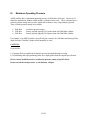
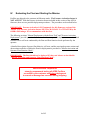
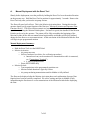
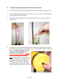
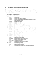
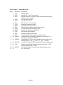
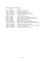
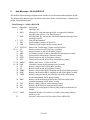
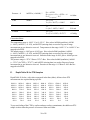
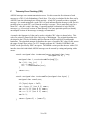
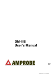
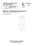
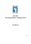
WEBB RESEARCH CORPORATION
82 Technology Park Drive • E. Falmouth, Massachusetts 02536-4441 • Telephone (508) 548-2077
FAX (508) 540-1686 • [email protected]
APEX PROFILER USER MANUAL
Applies to Serial Numbers:3975~3974
Revision Date:
Customer Name: CSIRO
WRC Job Number: 1506
Firmware Revision
Features:
04/25/08
APF9A F/W 013108
APF9A Controller
Park and Profile with 20- or 28-bit ARGOS ID
Deep Profile First (DPF)
Pressure Activation (optional)
I.
Alkaline Battery Warning ________________________________________________ 3
II.
APF9 Operations Warning for APF8 Operators ____________________________ 4
III.
Maximum Operating Pressure __________________________________________ 5
IV.
Evaluating the Float and Starting the Mission _____________________________ 6
A.
Manual Deployment with the Reset Tool_________________________________________ 7
B.
Pressure Activation Deployment _______________________________________________ 8
C.
Mission Activation and Mission Prelude ARGOS Transmissions_____________________ 9
D.
Mission Activation and Operator Float Function Check ___________________________ 10
E.
Notes and Caveats __________________________________________________________ 13
V.
Deploying the Float _____________________________________________________ 14
VI.
Park and Profile _____________________________________________________ 15
A.
Profile Ascent Timing _______________________________________________________ 15
B.
Profile and Profile Cycle Schematics ___________________________________________ 16
VII.
Deep Profile First (DPF)_______________________________________________ 17
VIII.
ARGOS Data ______________________________________________________ 18
A.
SERVICE ARGOS Parameters _______________________________________________ 18
B.
Test Messages - 28-bit ARGOS ID - Mission Prelude _____________________________ 19
C.
Data Messages - 28-bit ARGOS ID_____________________________________________ 22
D.
Conversion from Hexadecimal to Physical Units _________________________________ 27
E.
Depth Table 26 for PTS Samples ______________________________________________ 28
F.
Telemetry Error Checking (CRC) _____________________________________________ 29
IX.
Missions ____________________________________________________________ 30
Appendix A: Surface Arrival Time and Total Surface Time ______________________ 35
Appendix B: Argos ID formats, 28-bit and 20-bit ________________________________ 36
Appendix C: Storage conditions ______________________________________________ 36
Appendix D: Connecting a Terminal __________________________________________ 37
Appendix E: APF9A Command Summary _____________________________________ 38
Appendix F: Returning APEX floats for factory repair or refurbishment____________ 41
Appendix G: CTD Calibration and Ballasting records ___________________________ 42
2 of 42
I.
Alkaline Battery Warning
The profiler contains batteries comprised of alkaline manganese dioxide "D" cells.
There is a small but finite possibility that batteries of alkaline cells will release a combustible gas
mixture. This gas release generally is not evident when batteries are exposed to the atmosphere,
as the gases are dispersed and diluted to a safe level. When the batteries are confined in a sealed
instrument mechanism, the gases can accumulate and an explosion is possible.
Webb Research Corp. has added a catalyst inside of these instruments to recombine hydrogen
and oxygen into H2O, and the instrument has been designed to relieve excessive internal pressure
buildup by having the upper end cap release.
Webb Research Corp. knows of no way to completely eliminate this hazard. The user is warned,
and must accept and deal with this risk in order to use this instrument safely as so provided.
Personnel with knowledge and training to deal with this risk should seal or operate the
instrument.
Webb Research Corp. disclaims liability for any consequences of combustion or explosion.
3 of 42
II.
APF9 Operations Warning for APF8 Operators
This APEX manual describes floats using a new controller design. The new design is designated
APF9. The prior design, which is still in production and widely used, is designated APF8.
The operator interface and behavior of the APF9 are similar to, but not identical to, the operator
interface and behavior of the APF8. If you are an experienced APF8 user, please observe
appropriate cautions and do not assume an expected behavior. Several important differences
are listed below. These points should also be helpful to those without an APF8 background.
• To reset an APF9 for a deployment you should hold the Reset Tool stationary against the
RESET label until you hear the air pump run. Typically, the air pump will run 2 to 3 seconds
after you position the Reset Tool over the RESET label. (For the APF8 it was necessary to
hold the Reset Tool in place and then remove it to trigger the float.)
• The serial baud rate for communications is 9600, with 8 data bits, no parity, and 1 stop bit.
(The APF8 baud rate is 1200.)
• If not already in Command Mode, an APF9 can only enter Command Mode from Sleep.
Either the Reset Tool or a keystroke at the terminal will trigger the transition from Sleep to
Command Mode.
• If the APF9 is performing some task (e.g., self tests), it is not listening and cannot be placed in
Command Mode with either the Reset Tool or a keystroke at the terminal.
o There is one exception. If the piston is moving, the Reset Tool (but not a
keystroke) can be used to terminate the move. The APF9 will transition to its next
state or task. Typically this will be either Command Mode or Sleep, so try a
keystroke or a second application of the Reset Tool after the piston stops to
confirm or trigger the transition to Command Mode.
• If the APF9 is not responding, it is probably busy with some task. Be patient and occasionally
try to get the attention of the float with either the Reset Tool or a keystroke.
4 of 42
III.
Maximum Operating Pressure
APEX profilers have a maximum operating pressure of 2000 dbar (2900 psi). However, for
shallower applications, thinner walled pressure cylinders can be used. These cylinders have a
reduced pressure rating, but less mass, which allows them to carry a larger battery payload.
Three cylinder pressure ratings are available:
• 2000 dbar
• 1500 dbar
• 1200 dbar
maximum pressure rating
battery payload typically 14% greater than with 2000 dbar cylinder
battery payload typically 28% greater than with 2000 dbar cylinder
For example, if an APEX profiler is specified by the customer for 1400 dbar maximum (profile)
depth, then the 1500 dbar cylinder would normally be used.
CAUTION:
If you will be:
• Exposing floats to significant hydrostatic pressure during ballasting or testing
• Re-ballasting and re-programming floats for a depth greater than the original specification
Please contact Webb Research to confirm the pressure rating of specific floats.
Do not exceed the rated pressure, or the hull may collapse.
5 of 42
IV.
Evaluating the Float and Starting the Mission
Profilers are shipped to the customer in Hibernate mode. The Pressure Activation feature is
NOT ACTIVE. With the Pressure Activation feature included in this version of the APF9A
firmware, there are two possible deployment procedures. The procedures are described below.
IMPORTANT: Pressure Activation is NOT automatic for this firmware version of the
APF9A. The Pressure Activation feature MUST be MANUALLY ACTIVATED by the
OPERATOR using a PC to communicate with the float.
The following sections, "Manual Deployment with the Reset Tool" and "Pressure Activation
Deployment", provide operational summaries for these two possible deployment scenarios. Both
sections refer to self tests conducted by the float and float function checks performed by the
operator.
A detailed description of proper float behavior, self tests, and the associated operator actions and
observations needed to evaluate the float for deployment is provided in "Mission Activation and
Operator Float Function Check".
IMPORTANT: The float should not be deployed if it does not behave as described in
"Mission Activation and Operator Float Function Check".
Webb Research Corporation
strongly recommends testing all APEX Profilers
on receipt by the customer and before deployment
to ensure no damage has occurred during shipping.
6 of 42
A.
Manual Deployment with the Reset Tool
Shortly before deployment, reset the profiler by holding the Reset Tool over the marked location
on the pressure case. Hold the Reset Tool in position for approximately 3 seconds. Remove the
Reset Tool only after you hear the air pump activate.
The float will run a brief self test. This is the Mission Activation phase. During this time the
operator should verify proper function of the float (see "Mission Activation and Operator Float
Function Check"). The float will then transmit test messages for 6 hours at the programmed
repetition rate during the Mission Prelude phase. Six hours is typical; the duration of the Mission
Prelude can be set by the operator. The piston will be fully extended at the beginning of the
Mission Prelude (before the test transmissions begin) and the air bladder will be fully inflated
during the first dozen or so test transmissions. At the conclusion of the Mission Prelude the float
will begin its pre-programmed mission.
Manual Deployment Summary:
• Hold the Reset Tool over the RESET label
• Mission Activation
o Air pump runs once
o Self test conducted (see below for verification procedure)
§ Internal tests run (can be monitored if communication cable is connected,
see "Connecting a Terminal")
§ 6 ARGOS transmissions
o Piston EXTENDED fully
• Mission Prelude
o Test transmissions at the programmed repetition rate
o Mission Prelude duration is typically 6 hours
o Air pump run during transmissions until air bladder is fully inflated
The float can be deployed after the Mission Activation phase and confirmation of proper float
function have been successfully completed. We advise waiting until the air bladder is fully
inflated during the first dozen or so test transmissions of the Mission Prelude before deploying
the float.
7 of 42
B.
Pressure Activation Deployment
To use the Pressure Activation feature you must first connect the provided communication cable
between your PC and the float (see "Connecting a Terminal" at the end of this manual for
additional information). The normal port settings for an APF9A are 9600, 8, N 1. Press
[ENTER] to wake the float from Hibernate mode. The float will respond that it has detected an
"asynchronous wake-up" and will enter Command mode. Press [ENTER] in Command mode to
display the main menu. Menu selections are not case sensitive.
Press 'a' or 'A' to activate the Pressure Activation feature and start the deployment. The float will
run a brief self test (Mission Activation). During this time the operator should verify proper
function of the float (see below - Mission Activation and Operator Float Function Check). The
float will then fully retract the piston and deflate the air bladder so that it can sink when
deployed. Once the piston is fully retracted, the float enters the Pressure Activation phase.
During this phase the float makes a pressure measurement every two hours, hibernating between
measurements. If the pressure is less than 25 dbar the float returns to hibernation. If the pressure
exceeds 25 dbar the float fully extends the piston and begins the Mission Prelude with test
transmissions and air bladder inflation.
During the Pressure Activation phase the operator can communicate with the float. This does
NOT NORMALLY deactivate Pressure Activation. However, a 'k' or 'K' (kill) command during
this phase will deactivate Pressure Activation and stop the mission.
DO NOT DEPLOY THE FLOAT AFTER A KILL (K) COMMAND UNLESS YOU HAVE
STARTED A MANUAL DEPLOYMENT OR RESTARTED A PRESSURE
ACTIVATION DEPLOYMENT. IF YOU FAIL TO OBSERVE THIS CAUTION AND
LAUNCH THE FLOAT IT WILL SINK TO A NEUTRAL DEPTH AND STAY THERE.
IT WILL NOT SURFACE AGAIN.
In the absence of a kill command the float will automatically resume the Pressure Activation
phase after several minutes without operator input. Placing the Reset Tool over the RESET mark
during the Pressure Activation phase will start a deployment.
Pressure Activation Deployment Scenario
Using the Pressure Activation feature minimizes operator/float interaction while at sea. A skilled
operator can fully test the float while still in the laboratory environment or while the vessel is still
at the dock. At the conclusion of testing the Pressure Activation feature can be activated and the
float can be left to await deployment. When the vessel is on-station it only remains to launch the
float (see "Deploying the Float"). No further communications with the float is required and the
float can be reliably deployed by relatively inexperienced personnel.
8 of 42
One caution is in order. The air bladder is not automatically inflated until the beginning of the
Mission Prelude phase of a deployment. This means it cannot be checked by the operator for
leaks during the normal course of a Pressure Activation deployment. Therefore, we strongly
recommend that you either:
• Manually inflate and check the air bladder before starting a Pressure Activation
deployment. Be sure to manually close the air valve before trying to inflate the air bladder.
Starting a Pressure Activation deployment will automatically deflate the bladder.
Or:
• Start a Manual Deployment with the Reset Tool or an operator command and reassert
operator control after the Mission Activation and initial portion of the Mission Prelude
phases, with attendant operator float function check, has successfully completed.
Pressure Activation Deployment Summary:
• Establish communication with the float (see "Connecting a Terminal")
• Press 'a' or 'A'
• Mission Activation
o Air pump runs once
o Self test conducted (see below for verification procedure)
§ Internal tests run (can be monitored if communication cable is connected,
see "Connecting a Terminal")
§ 6 ARGOS transmissions
o Air bladder deflated
o Piston RETRACTED fully
• Deploy the float
• Pressure Activation
o Pressure measured every 2 hours
o Pressure in excess of 25 dbar extends piston, inflates air bladder, triggers
transition to Mission Prelude
• Mission Prelude
o Test transmissions (6 hours typical)
o Air pump run during transmissions until air bladder is fully inflated
The float can be deployed after the Mission Activation phase and proper functioning of the float
have been successfully completed.
C.
Mission Activation and Mission Prelude ARGOS Transmissions
The six ARGOS transmissions during Mission Activation and the transmissions during the
Mission Prelude contain data about the instrument. The information needed to decode these
messages is provided in the "ARGOS Data" section of this manual.
9 of 42
D.
Mission Activation and Operator Float Function Check
1)
Secure the float in a horizontal position using the foam cradles from the shipping crate.
2)
The minimum internal temperature of the float is -2.0°C. If necessary, allow the float to
warm up indoors before proceeding.
3)
Remove the plastic bag and three (3) plugs from the CTD sensor as shown in the two
images below.
4)
Carefully remove the black rubber plug from the bottom center of the yellow cowling as
shown in the image below. This will allow you to verify air bladder inflation in the steps
below. Use only your fingers to remove
the plug. Tools may puncture or
otherwise harm the bladder. Be sure to
replace the plug before deployment!
Note: It can be difficult to replace the plug
when the air bladder is fully inflated. We
suggest that you reinsert the plug before
the bladder is fully inflated. The plug
prevents the entry of silt into the cowling
in the event the float contacts the sea floor.
10 of 42
5)
Start a Manual or Pressure Activated Deployment as described above in the "Manual
Deployment with the Reset Tool" and "Pressure Activation Deployment" sections. This
will trigger the Mission Activation self tests. Where applicable, the description below
indicates where the two versions of the self tests differ.
Verify by ear that the air pump is activated for approximately 1 second.
DO NOT DEPLOY THE FLOAT IF IT DOES NOT BEHAVE AS DESCRIBED
BELOW. FLOATS THAT DO NOT PASS THE SELF TESTS SHOULD NOT BE
DEPLOYED. CONTACT WEBB RESEARCH FOR ASSISTANCE.
6)
The float will conduct self tests for approximately 15 seconds. Progress and diagnostic
messages will be displayed if a terminal is connected to the float (see "Connecting a
Terminal" for additional information).
7)
If the float passes the self tests,
it will make 6 ARGOS
transmissions with a 6 second
interval. You can detect these
transmissions using the "cat's
meow" sensor as shown in the
image at right. Hold the sensor
parallel to and within 15 cm
(6 inches) of the float's antenna.
The cat's meow will beep during
each ARGOS transmission. Do
not deploy the float if you do not
detect the six (6) ARGOS
transmissions.
8)
= 15 cm
Manual Deployment: If not
Float Antenna
already fully extended, the float
will fully extend the piston.
This process may require up to
25 minutes. The oil bladder will expand during this time.
“Cat's Meow “
Transmission detector
Pressure Activated Deployment: If not already fully retracted, the float will fully retract the
piston. This process may require up to 25 minutes. The oil bladder will deflate during this
time.
The volume of oil in the bladder is difficult to detect by hand. You may be able to hear the
pump by placing your ear against the hull.
11 of 42
9)
Manual Deployment: Once the piston is fully extended the float enters the Mission Prelude
phase. During this phase it will transmit test messages at the operator specified ARGOS
repetition period. These transmissions can be detected with the Cat's Meow. The float will
run the air pump for 6 seconds during each test transmission until the air bladder is fully
inflated. Inflating the air bladder typically requires 8 to 10 repetitions. Check for air
bladder inflation by sticking your finger (not a tool!) through the hole in the bottom of the
yellow cowling as described in Step (4) above. Don't forget to replace the plug before
deploying the float.
The duration of the Mission Prelude is set by the operator. 6 hours is typical. At the end of
the Mission Prelude the ARGOS test transmissions will cease, the float will deflate the air
bladder and retract the piston, and the first descent of the programmed mission will begin.
Pressure Activated Deployment: Once the piston is fully retracted the float will enter the
Pressure Activation phase. During this phase it will check the pressure every two hours,
hibernating in between. The float will not enter the Mission Prelude phase until it detects a
pressure in excess of 25 dbar. There will be no test transmissions nor inflation of the air
bladder until the Mission Prelude phase begins.
When the trigger pressure is detected the float will extend the piston and begin the Mission
Prelude, making ARGOS test transmissions at the specified repetition rate and also running
the air pump to inflate the air bladder (see above). The duration of the Mission Prelude is
set by the operator. 6 hours is typical. At the end of the Mission Prelude the ARGOS test
transmissions will cease, the float will deflate the air bladder and retract the piston, and the
first descent of the programmed mission will begin
10) The float is ready to deploy.
12 of 42
E.
Notes and Caveats
Self Tests: During the self tests the float checks:
• The internal vacuum
• Communication with the CTD
• The internal alarm timer settings
If any of the self tests fail the float will abort the mission. The clearest indication to the operator
that this has occurred is the failure of the float to make the initial 6 ARGOS transmissions at
6 second intervals.
If you do not detect these Mission Activation transmissions with the Cat's Meow,
DO NOT DEPLOY THE FLOAT!
Manual Deployment: In the case of a Manual deployment, if the float is not deployed before the
completion of the Mission Prelude phase,
RESET the float again and wait for it to complete the Mission Activation phase and begin
the Mission Prelude before you deploy it.
Pressure Activated Deployment: In the case of a Pressure Activated Deployment, the operator is
necessarily absent when the float begins the Mission Prelude. This means the operator does not
have the opportunity to check the air bladder for leaks that a Manual Deployment offers.
For this reason we strongly recommend that you manually inflate and check the bladder
before starting a Pressure Activated Deployment.
13 of 42
V.
Deploying the Float
1)
Pass a rope through the hole in the plastic
damper plate, which is shown in the image at
right. The rope should fit easily through the hole
and be capable of supporting 50 kg (100 lb).
2)
Holding both ends of the rope bight, carefully
lower the float into water. The damper plate is
amply strong enough to support the weight of
the float. However, do not let rope slide rapidly
through the hole as this may cut the plastic disk and release the float prematurely.
3)
Take care not to damage the CTD or the ARGOS antenna against the side of the ship while
lowering the float.
4)
Do not leave the rope with the instrument. Once the float is in the water, let go of the
lower end of the rope and pull on the top end slowly and carefully until the rope clears the
hole and the float is released.
It may take several minutes for the cowling to fully flood with water and the float may drift
at an angle or even rest on its side during this period. This is normal behavior and not a
cause for concern.
5)
Manual Deployment: The float will remain on surface for the duration of the Mission
Prelude.
Pressure Activated Deployment: The float will sink immediately. It will return to the
surface within 3 hours and begin the Mission Prelude after detecting a pressure in excess of
25 dbar.
14 of 42
VI.
Park and Profile
The APF9A float can be set to profile from a maximum depth (Profile Depth) after a
programmable number (N) of profiles from a shallower depth (Park Depth). Special cases are
conducting all profiles from either the Profile Depth or the Park Depth. The latter is an important
special case that can be selected by setting N = 254. This will cause all profiles start at the Park
Depth; the programmed Profile Depth is ignored. Between profiles the float drifts at the Park
Depth.
Terminology:
? Park Depth
A.
?
Profile Depth
?
Down Time
?
Up Time
?
Ascent Rate
Intermediate depth at which the float drifts between profiles and from
which the float profiles in cycles not evenly divisible by N.
Maximum depth to which the float descends from the Park Depth
every Nth cycle and from which each Nth profile is conducted.
Programmed time-limit for descending from the surface and drifting
at the Park Depth. Down Time is commonly set to 10 days or to
10 days less the Up Time.
Programmed time-limit for ascending from the Park or the Profile
Depth and drifting at the surface while transmitting the data acquired
during the profile. Up Time is typically set between 12 hours and
20 hours, increasing with the amount of data to be transmitted per
profile. The latitude of the deployment also matters; ARGOS
satellites are in polar orbits, so the number of satellite passes per day
increases with latitude.
The ascent rate of the float is maintained at or above 8 cm/s. The
float extends the piston by a user specified amount to add buoyancy
when the ascent rate falls below this threshold.
Profile Ascent Timing
Profiles from the Park Depth begin when the operator programmed Down Time expires. The
float extends the piston by an operator programmed initial amount and begins the ascent.
When a profile is to begin from the Profile Depth, the float will retract the piston and descend
from the Park Depth an operator programmed interval before the expiration of the Down Time.
This interval, Parameter Mtj, Deep-profile descent time in hours, provides the additional time
needed to descend to and profile from the Profile Depth without losing significant surface time,
the period when data from the profile are transmitted.
15 of 42
B.
Profile and Profile Cycle Schematics
Down Time
Up Time
Surface
Park Depth
Profile Depth
Time
N=1
Deep Profile every cycle
N=3
Deep Profile every third cycle
Time
16 of 42
VII.
Deep Profile First (DPF)
Independent of the Park and Profile cycle length, the first profile is always a Deep Profile that
begins at the Profile Depth. This means the float returns a CTD profile relatively soon, typically
less than a day, after the float is deployed. This feature supports comparison of the initial float
profile with a conventional CTD cast from the ship.
The first descent begins at the end of the Mission Prelude. A schematic representation of DPF
with a Park and Profile parameter N = 2 is shown below.
N = 2 and Deep Profile First (DPF)
Deep Profile on first cycle and every second cycle
Time
Note: For maximum battery life in ARGO applications, WRC recommends use of PD > one,
with park depth < 1500 db.
17 of 42
VIII. ARGOS Data
A.
SERVICE ARGOS Parameters
Each float operator must specify various options to Service ARGOS. These choices depend on
how the user plans to receive and process data. Typical Service ARGOS Parameters are:
•
•
•
•
•
•
Standard location
Processing:
Result (output) format:
Compression:
Distribution strategy:
Number of bytes transmitted:
Type A2
Binary input, hexadecimal output
DS
All results from each satellite pass
None
Uncompressed
Scheduled
All results every 24 hours
31 per message1
1
When using a 28-bit ARGOS ID, 31 data bytes are transmitted in each message. 32 data bytes are transmitted in
each message when using a 20-bit ARGOS ID.
18 of 42
B.
Test Messages - 28-bit ARGOS ID - Mission Prelude
The test message block is comprised of two messages. Each of the 6 messages sent during the
Mission Activation phase is a Test Message 1. During the Mission Prelude the two test messages
alternate, with one sent during each ARGOS transmission. The formats of the two test messages
are show in the tables below:
Test Message 1 - 28-bit ARGOS ID
Byte(s) Mnemonic Description
1 CRC
Message CRC
2 MSG
Message ID - 1 for Test Message 1
3 BLK
Message block ID - increments with each transmitted message
block and wraps at 0xFF
F/W Revision - Month
4 MON
5 DAY
F/W Revision - Day
F/W Revision - Year (2-digit)
6 YR
Float ID (hull number)
7 - 8 FLT
9 - 10 SEC
Time since the start of the Mission Prelude [seconds]
11 - 12 STATUS Float status word - 16 bits, see below
Pressure measured once for each test message block [centibars]
13 - 14 P
15 VAC
Vacuum measured during self tests [counts]
Air bladder pressure measured once for each test message block
16 ABP
[counts]
17 BAT
Quiescent battery voltage measured once for each test message
block [counts]
Up time [hours]
18 UP
Down time [hours]
19 - 20 DOWN
21 - 22 PRKP
Park pressure [decibars]
23 PPP
Park piston position [counts]
24 NUDGE
Buoyancy nudge during ascent [counts]
25 OK
Internal vacuum threshold [counts]
26 ASCEND Ascent time-out [hours]
Maximum air bladder pressure [counts]
27 TBP
28 - 29 TP
Profile pressure [decibars]
30 TPP
Profile piston position [counts]
31 N
Park and profile cycle length
32
Not used - only exists for a float with a 20-bit ARGOS ID
19 of 42
Test Message 2 - 28-bit ARGOS ID
Byte(s) Mnemonic Description
1 CRC
Message CRC
2 MSG
Message ID - 2 for Test Message 2
3 BLK
Message block ID - increments with each transmitted message
block and wraps at 0xFF
4 MON
F/W Revision - Month
5 DAY
F/W Revision - Day
6 YR
F/W Revision - Year (2-digit)
7 FEXT
Piston full extension [counts]
8 FRET
Piston full retraction [counts]
9 IBN
Initial buoyancy nudge (starts profile) [counts]
10 CHR
Compensator hyper-retraction [counts]
Deep profile descent period [hours]
11 DPDP
Park descent period [hours]
12 PDP
13 PRE
Mission prelude period [hours]
ARGOS transmission repetition period [seconds]
14 REP
Seabird SBE41 serial number (encoded as a hex integer, e.g.,
15 – 16 SBESN
S/N 8413 is encoded as 0x20DD)
17 - 18 SBEFW
Seabird SBE41 F/W Revision (encoded as a hex integer after
multiplication by 100, e.g., F/W 2.6 ? 260 ? 0x0104)
Current UNIT epoch (GMT) of Apf9a RTC (little endian order)
19 - 22 EPOCH
Minutes past midnight when down-time will expire. If ToD
23 - 24 TOD
feature disabled, bytes = 0xfffe.
25 - 26 DEBUG
Debugging Verbosity for generating engineering log entries.
Not used [0xFF]
27 – 32
20 of 42
Test Message 1 - Status Word - 16 bits
Bit
Mnemonic
Description
0x0001 DeepProfile
Current profile is a Deep Profile
0x0002 ShallowWaterTrap Shallow water trap detected
0x0004 Obs25Min
Sample time-out (25 minutes) expired
0x0008 PistonFullExt
Piston fully extended before surface detected
0x0010 AscentTimeOut
Ascent time-out expired
0x0020 TestMsg
Current message is a test message
0x0040 PreludeMsg
Current messaged transmitted during Mission Prelude
0x0080 PActMsg
Current message is a Pressure Activation test message
0x0100 BadSeqPnt
Invalid sequence point detected
0x0200 Sbe41PFail
SBE41 pressure measurement exception
SBE41 pressure-temperature measurement exception
0x0400 Sbe41PtFail
SBE41 pressure-temperature-salinity measurement exception
0x0800 Sbe41PtsFail
0x1000 Sbe41Unreliable
SBE41 pressure measurement unreliable
Air inflation system bypassed; excessive energy consumption.
0x2000 AirSysBypass
Wake-up by watchdog alarm
0x4000 WatchDogAlarm
0x8000 PrfIdOverFlow
8-bit profile counter overflowed [255 ? 0]
21 of 42
C.
Data Messages - 28-bit ARGOS ID
The number of data messages depends on the number of measurements made during the profile.
The formats of the data messages are shown in the tables below. Data Message 1 contains float,
profile, and engineering data.
Data Message 1 - 28-bit ARGOS ID
Byte(s) Mnemonic Description
1 CRC
Message CRC
2 MSG
Message ID - each data message block is comprised of multiple
messages, this will be a 1 for Data Message 1
3 BLK
Message block ID - increments with each transmitted message block
and wraps at 0xFF
4 - 5 FLT
Float ID (hull number)
Profile number (wraps to 0 from 255)
6 PRF
Number of TSP samples in this message block
7 LEN
8 - 9 STATUS Same as the Test Message 1 Status word (see above)
Surface pressure at end of Up Time [centibars]
10 - 11 SP
Internal vacuum at end of Park phase [counts]
12 VAC
13 ABP
Air bladder pressure at end of each ARGOS transmission [counts]
Piston position when surface detected [counts]
14 SPP
Piston position at end of Park phase [counts]
15 PPP2
16 PPP
Piston position at end of last Deep descent phase [counts]
SBE41 status word - 16 bits, see below
17 - 18 SBE41
19 - 20 PMT
Cumulative piston on time during ascent [seconds]
21 VQ
Battery voltage at end of Park phase [counts]
Battery current at end of Park phase [counts]
22 IQ
23 VSBE
Battery voltage while SBE41 sampling at end of Park phase [counts]
24 ISBE
Battery current while SBE41 sampling at end of Park phase [counts]
25 VHPP
Battery voltage measured just before the end of the initial piston
extension beginning Profile phase [counts]
26 IHPP
Battery current measured just before the end of the initial piston
extension beginning Profile phase [counts]
27 VAP
Battery voltage while air pump running [counts]
Battery current while air pump running [counts]
28 IAP
29 PAP
Number of 6-second pulses of the air pump require to inflate the air
bladder.
30 - 31 VSAP
Integrated Measure of (Volt-Sec) of volume of air pumped during
telemetry cycle.
32
Not used - only exists for a float with a 20-bit ARGOS ID
22 of 42
The SBE41 status word is shown in the table below.
SBE41 Status Word - 16 bits
Bit
Mnemonic
Description
0x0001 Sbe41PedanticExceptn An exception was detected while parsing the P-only
pedantic regular expression
0x0002 Sbe41PedanticFail
The SBE41 response to P-only measurement failed the
pedantic regular expression
0x0004 Sbe41RegexFail
The SBE41 response to P-only measurement failed the
non-pedantic regular expression
0x0008 Sbe41NullArg
NULL argument detected during P-only measurement
0x0010 Sbe41RegExceptn
An exception was detected while parsing the P-only
non-pedantic regular expression
0x0020 Sbe41NoResponse
No response detected from SBE41 for P-only request
Not (yet) used
0x0040
Not (yet) used
0x0080
0x0100 Sbe41PedanticExceptn An exception was detected while parsing the PTS
pedantic regular expression
0x0200 Sbe41PedanticFail
0x0400 Sbe41RegexFail
The SBE41 response to PTS measurement failed the
pedantic regular expression
NULL argument detected during PTS measurement
0x0800 Sbe41NullArg
0x1000 Sbe41RegExceptn
An exception was detected while parsing the PTS nonpedantic regular expression
No response detected from SBE41 for PTS request
0x2000 Sbe41NoResponse
0x4000
Not (yet) used
Not (yet) used
0x8000
23 of 42
Data Message 2 continues with miscellaneous engineering data and statistics for the PTS
measurements taken periodically during the Park phase.
Data Message 2 - 28-bit ARGOS ID
Byte(s) Mnemonic Description
1 CRC
Message CRC
2 MSG
Message ID - each data message block is comprised of multiple
messages, this will be a 2 for Data Message 2
3 - 6 EPOCH
Unix epoch when down time expired (Apf9a RTC)
7 - 8 TINIT
Time (minutes) when telemetry phase was initiated relative to
EPOCH. (2’s compliment signed integer)
9 NADJ
Number of active ballast adjustments made during Park phase/
10 – 11 ParkN
Number of samples collected during Park phase
12 – 13 TMean
Mean temperature during Park phase
Mean pressure during Park phase
14 – 15 PMean
Standard deviation of temperature during Park phase
16 – 17 StDevT
18 – 19 StDevP
Standard deviation of pressure during Park phase
Minimum temperature during Park phase
20 – 21 TMin
Pressure associated with minimum temperature during Park phase
22 – 23 TMinP
24 – 25 TMax
Maximum temperature during Park phase
Pressure associated with maximum temperature during Park phase
26 – 27 TMaxP
Minimum pressure during Park phase
28 - 29 PMin
30 – 31 PMax
Maximum pressure during Park phase
Not used - only exists for a float with a 20-bit ARGOS ID
32 NA
24 of 42
The hydrographic data are transmitted in messages 3 – N in the order that they were collected.
The sample taken at the end of the Park phase is transmitted first followed by the samples
collected during the profile phase.
Data Message 3 - 28-bit ARGOS ID
Byte(s) Mnemonic Description
1 CRC
Message CRC
2 MSG
Message ID - each data message block is comprised of multiple
messages, this will be a 2 for Data Message 2
3 - 4 Tp
Temperature at end of Park phase
5 - 6 Sp
Salinity at end of Park phase
7 - 8 Pp
Pressure at end of Park phase
9 – 10 T1
Temperature (first point in depth table)
11 – 12 S1
Salinity
Pressure
13 – 14 P1
Temperature (second point in depth table)
15 – 16 T2
17 – 18 S2
Salinity
Pressure
19 – 20 P2
Temperature (thri\d point in depth table)
21 – 22 T3
23 – 24 S3
Salinity
Pressure
25 – 26 P3
Temperature (etc. to end of table)
27 – 28 T4
29 – 30 S4
Salinity
Pressure (first byte, second byte in next message)
31 P4 (half)
32 NA
Not used - only exists for a float with a 20-bit ARGOS ID
The pattern of sequential PTS measurements continues in subsequent messages with
measurement triples breaking across message boundaries as necessary. The measurements each
occupy 2 bytes and are encoded as 4 hex characters. The procedures for converting these encoded
data from the hexadecimal format to physical units are described in the next section, "Conversion
from Hexadecimal to Physical Units".
25 of 42
Auxiliary Engineering Data
If there is space at the end of the last message in the block, it is filled with Auxiliary Engineering
data. These data are not used to generate an additional message and if they are not sufficient to
fill the available space the remaining bytes are set to 0xFF. These data are comprised of the time
of profile initiation plus a series of pressure measurements taken at just after the piston is
retracted and at hourly intervals during the descent to the Park Depth. Descent rates are
calculated from these data. The information begins in the byte immediately following the end of
the hydrographic data. The table below shows an example.
The byte immediately following the hydrographic data is the time of profile initiation (the time
difference in minutes between the start of the profile and the end of down time).
The descent pressure marks are next. The first byte is the count of the number of descent
pressure mark. The following bytes are the descent pressure measurements in bars.
Final Data Message - 28-bit ARGOS ID
Byte(s) Mnemonic Description
1 CRC
Message CRC
2 MSG
Message ID - each data message block is comprised of multiple
messages, this will be a 2 for Data Message 2
Pressure
3 - 4 PN-3
5 - 6 TN-2
Temperature
Salinity
7 - 8 SN-2
9 - 10 PN-2
Pressure
11 - 12 TN-1
Temperature (second to last point in depth table)
Salinity
13 - 14 SN-1
15 - 16 PN-1
Pressure
Temperature (last point in depth table)
17 - 18 TN
19 - 20 SN
Salinity
21 - 22 PN
Pressure
23 - 23 Ptime
Profile initiation time (minutes) 2’s compliment signed integer
(positive values – profile initiated after down time expired)
(negative values – profile initiated before down time expired)
24 NDM
Number of descent pressure measurements
25 DM1
Pressure taken at end of piston retraction
26 DM2
Pressure taken 1 hour after beginning of descent (bars)
27 DM3
Pressure taken 2 hours after beginning of descent (bars)
28 DM4
Pressure taken 3 hours after beginning of descent (bars)
29 DM5
Pressure taken 4 hours after beginning of descent (bars)
30 DM6
Pressure taken 5 hours after beginning of descent (bars)
30
Filler 0xFF
31
Filler 0xFF
32 NA
Not used - only exists for a float with a 20-bit ARGOS ID
26 of 42
D.
Conversion from Hexadecimal to Physical Units
The temperature, salinity, pressure, voltage, and current values measured by the float are encoded
in the Data Messages as hex integers. This compression reduces the number of bytes in the
ARGOS transmissions. The resolution of the encoded hydrographic values is shown in the table
below:
Measurement
Temperature
Salinity
Pressure
Volts
Current
Vacuum
Resolution Range
0.001 °C
-4.095 °C to
61.439 °C
0.001 psu -4.095 psu to
61.439 psu
0.1 dbar
-3276.7 dbar
to 3276.7 dbar
V
MA
InHg
Data Format
16-bit unsigned
with 2’s complement
16-bit unsigned
with 2’s complement
16-bit unsigned
with 2’s complement
8 bits unsigned
8 bits unsigned
8 bits unsigned
Conversion
T = Traw / 1000
S= Sraw / 1000
P= Praw /10
V = (Vraw * 0.077 + 0.486
I = (Iraw * 4.052) - 3.606
V = (Vraw * 0.293) -29.767
To convert the hex values in an ARGOS message back to physical units, proceed as described in
the table below. The initial conversion from Hexadecimal to Decimal should assume the hex
value is an unsigned integer with a range of 0 to 65535 for temperature, salinity, and pressure
measurements, a range of 0 to 255 for voltage and current measurements and a range of 0 to 4095
for optode measurements. If temperature, salinity or pressure raw values are above the maximum
unisigned value listed, a 2’s complement conversion should be applied to obtain a signed
(negative) value. This allows for representation of a full range of values.
Measurement
Hexadecimal
Temperature = 0
0x3EA6 (<0xEFFF) ?
Temperature < 0
Salinity
Salinity
Pressure = 0
0xF58B (= 0xF001) ?
0x8FDD (<0xEFFF) ?
0xF003 (= 0xF001) ?
0x1D4C (< 0x8000) ?
Decimal and
Conversion Steps
Physical
Result
Traw = 16038
T = Traw / 1000 ?
16.038 °C
Traw = 62859
T2sComplement=Traw–65536=-2677
T= T2sComplement / 1000 ?
Sraw = 36829
S= Sraw / 1000 ?
Sraw = 61443
S2sComplement=Sraw-65536= -4093
S= S2sCompement / 1000 ?
Praw = 7500
P = Praw / 10 ?
27 of 42
-2.677 °C
36.829 psu
-4.093 psu
750.0 dbar
Pressure < 0
Volts
0xFFFA (= 0x8000) ?
0xBB ?
Current
0x0A ?
Vacuum
0x56 ?
Praw = 65530
P2sCompliment = Praw - 65536 = -6
P = P2sCompliment / 10 ?
-0.6 dbar
Vraw = 187
V= (Vraw *0.077) + 0.486 ?
14.9 V
Iraw = 10
I = (Iraw * 4.052) –3.606 ?
36.9 mA
Vraw = 86
V = (Vraw* 0.293) -29.767 ?
-4.5 inHg
Conversion Notes:
The temperature range is -4.095 °C to 61.439 °C. Hex values 0xF000 (nonfinite), 0xF001
(= -4.095), 0xEFFF (= 61.439), and 0xFFFF (missing data) are used to flag out-of-range
measurements or are otherwise reserved. Temperatures in the range -0.0015 °C to -0.0005 °C are
mapped to 0xFFFE.
The salinity range is -4.095 psu to 61.439 psu. Hex values 0xF000 (nonfinite), 0xF001
(= -4.095), 0xEFFF (= 61.439), and 0xFFFF (missing data) are used to flag out-of-range
measurements or are otherwise reserved. Salinities in the range -0.0015 psu to -0.0005 psu are
mapped to 0xFFFE.
The pressure range is -3276.7 dbar to 3276.7 dbar. Hex values 0x8000 (nonfinite), 0x8001
(= -3276.7), 0x7FFF (= 32767.7), and 0xFFFF (missing data) are used to flag out-of-range
measurements or are otherwise reserved. Pressures in the range -0.15 dbar to -0.05 dbar are
mapped to 0xFFFE.
E.
Depth Table 26 for PTS Samples
Depth Table 26, below, with values expressed in decibars (dbar), defines where PTS
measurements are acquired during a profile.
2000.0
1600.0
1200.0
800.0
400.0
300.0
220.0
140.0
60.0
1950.0
1550.0
1150.0
750.0
380.0
290.0
210.0
130.0
50.0
1900.0
1500.0
1100.0
700.0
360.0
280.0
200.0
120.0
40.0
1850.0
1450.0
1050.0
650.0
350.0
270.0
190.0
110.0
30.0
1800.0
1400.0
1000.0
600.0
340.0
260.0
180.0
100.0
20.0
1750.0
1350.0
950.0
550.0
330.0
250.0
170.0
90.0
10.0
1700.0
1300.0
900.0
500.0
320.0
240.0
160.0
80.0
6.0
1650.0
1250.0
850.0
450.0
310.0
230.0
150.0
70.0
0.0
To prevent fouling of the CTD by surface and near-surface contaminants, the shallowest PTS
sample is taken when the pressure is between 6 dbar and 4 dbar.
28 of 42
F.
Telemetry Error Checking (CRC)
ARGOS messages can contain transmission errors. For this reason the first element of each
message is a CRC (Cyclic Redundancy Check) byte. The value is calculated by the float, not by
ARGOS, from the remaining bytes of that message. A bad CRC generally means a corrupted
message. It is worth noting that a good CRC is a good indicator that the message is OK, but it is
possible to have a good CRC even when the message is corrupt. This is particularly true for a
short CRC - this one is only 8 bits long. Comparing multiple realizations of each ARGOS
message (e.g., all received versions of Data Message 3 for some particular profile) to identify
uncorrupted versions of the message is strongly recommended.
A sample code fragment in C that can be used to calculate CRC values is shown below. This
code was written by Dana Swift of the University of Washington. The original algorithm was
developed in the 1970s by Al Bradley and Don Dorson of the Woods Hole Oceanographic
Institution. The algorithm attempts to distribute the space of possible CRC values evenly across
the range of single byte values, 0 to 255. Sample programs in C, Matlab, FORTRAN, and
BASIC can be provided by WRC on request. The Matlab version provides the user with a GUI
interface into which individual ARGOS messages can be entered by cutting and pasting with a
mouse.
static unsigned char CrcDorson(const unsigned char *msg,
unsigned int n) {
unsigned char i,crc=CrcScrambler(msg[1]);
for (i=2; i<n; i++)
{
crc ^= msg[i];
crc = CrcScrambler(crc);
}
return crc;
}
static unsigned char CrcScrambler(unsigned char byte) {
unsigned char sum=0,tst;
if (!byte) byte = 0xff;
tst
tst
tst
tst
= byte; if (tst % 2) sum++;
>>= 2; if (tst % 2) sum++;
>>= 1; if (tst % 2) sum++;
>>= 1; if (tst % 2) sum++;
sum %= 2;
}
return (byte>>1) + (sum<<7);
29 of 42
IX.
Missions
This section lists the parameters for each float covered by this manual.
To display the parameter list, connect a communications cable to the float, press <ENTER> to
wake the float from hibernate and start command mode, and press 'l' or 'L' to list the parameters.
See "Connecting a Terminal" and "APF9A Command Summary" for more information.
INSTRUMENT# 3975
APEX version 013108 sn 6037
1598C13 28-bit hex Argos id.
Ma
042 Argos repetition period (Seconds)
Mr
INACTV ToD for down-time expiration. (Minutes) Mtc
225 Down time. (Hours)
Mtd
015 Up time. (Hours)
Mtu
009 Ascent time-out. (Hours)
Mta
005 Deep-profile descent time. (Hours)
Mtj
005 Park descent time. (Hours)
Mtk
006 Mission prelude. (Hours)
Mtp
1000 Park pressure. (Decibars)
Mk
2000 Deep-profile pressure. (Decibars)
Mj
066 Park piston position. (Counts)
Mbp
000 Compensator hyper-retraction. (Counts) Mbh
016 Deep-profile piston position. (Counts) Mbj
010 Ascent buoyancy nudge. (Counts)
Mbn
022 Initial buoyancy nudge. (Counts)
Mbi
001 Park-n-profile cycle length.
Mn
120 Maximum air bladder pressure. (Counts) Mfb
096 OK vacuum threshold. (Counts)
Mfv
226 Piston full extension. (Counts)
Mff
100 Piston storage position. (Counts)
Mfs
2 Logging verbosity. [0-5]
D
0002 DebugBits.
D
de59 Mission signature (hex).
INSTRUMENT# 3976
APEX version 013108 sn 6038
1598C26 28-bit hex Argos id.
Ma
042 Argos repetition period (Seconds)
Mr
INACTV ToD for down-time expiration. (Minutes) Mtc
225 Down time. (Hours)
Mtd
015 Up time. (Hours)
Mtu
009 Ascent time-out. (Hours)
Mta
005 Deep-profile descent time. (Hours)
Mtj
005 Park descent time. (Hours)
Mtk
006 Mission prelude. (Hours)
Mtp
1000 Park pressure. (Decibars)
Mk
2000 Deep-profile pressure. (Decibars)
Mj
066 Park piston position. (Counts)
Mbp
000 Compensator hyper-retraction. (Counts) Mbh
016 Deep-profile piston position. (Counts) Mbj
010 Ascent buoyancy nudge. (Counts)
Mbn
022 Initial buoyancy nudge. (Counts)
Mbi
001 Park-n-profile cycle length.
Mn
120 Maximum air bladder pressure. (Counts) Mfb
096 OK vacuum threshold. (Counts)
Mfv
227 Piston full extension. (Counts)
Mff
100 Piston storage position. (Counts)
Mfs
2 Logging verbosity. [0-5]
D
0002 DebugBits.
D
1cc9 Mission signature (hex).
30 of 42
INSTRUMENT# 3977
APEX version 013108 sn 6039
1598C35 28-bit hex Argos id.
Ma
044 Argos repetition period (Seconds)
Mr
INACTV ToD for down-time expiration. (Minutes) Mtc
225 Down time. (Hours)
Mtd
015 Up time. (Hours)
Mtu
009 Ascent time-out. (Hours)
Mta
005 Deep-profile descent time. (Hours)
Mtj
005 Park descent time. (Hours)
Mtk
006 Mission prelude. (Hours)
Mtp
1000 Park pressure. (Decibars)
Mk
2000 Deep-profile pressure. (Decibars)
Mj
066 Park piston position. (Counts)
Mbp
000 Compensator hyper-retraction. (Counts) Mbh
016 Deep-profile piston position. (Counts) Mbj
010 Ascent buoyancy nudge. (Counts)
Mbn
022 Initial buoyancy nudge. (Counts)
Mbi
001 Park-n-profile cycle length.
Mn
120 Maximum air bladder pressure. (Counts) Mfb
096 OK vacuum threshold. (Counts)
Mfv
226 Piston full extension. (Counts)
Mff
100 Piston storage position. (Counts)
Mfs
2 Logging verbosity. [0-5]
D
0002 DebugBits.
D
aedf Mission signature (hex).
INSTRUMENT# 3978
APEX version 013108 sn 6040
1598C4C 28-bit hex Argos id.
Ma
044 Argos repetition period (Seconds)
Mr
INACTV ToD for down-time expiration. (Minutes) Mtc
225 Down time. (Hours)
Mtd
015 Up time. (Hours)
Mtu
009 Ascent time-out. (Hours)
Mta
005 Deep-profile descent time. (Hours)
Mtj
005 Park descent time. (Hours)
Mtk
006 Mission prelude. (Hours)
Mtp
1000 Park pressure. (Decibars)
Mk
2000 Deep-profile pressure. (Decibars)
Mj
066 Park piston position. (Counts)
Mbp
000 Compensator hyper-retraction. (Counts) Mbh
016 Deep-profile piston position. (Counts) Mbj
010 Ascent buoyancy nudge. (Counts)
Mbn
022 Initial buoyancy nudge. (Counts)
Mbi
001 Park-n-profile cycle length.
Mn
120 Maximum air bladder pressure. (Counts) Mfb
096 OK vacuum threshold. (Counts)
Mfv
226 Piston full extension. (Counts)
Mff
100 Piston storage position. (Counts)
Mfs
2 Logging verbosity. [0-5]
D
0002 DebugBits.
D
ab7d Mission signature (hex).
31 of 42
INSTRUMENT# 3979
APEX version 013108 sn 6041
1598C5F 28-bit hex Argos id.
Ma
046 Argos repetition period (Seconds)
Mr
INACTV ToD for down-time expiration. (Minutes) Mtc
225 Down time. (Hours)
Mtd
015 Up time. (Hours)
Mtu
009 Ascent time-out. (Hours)
Mta
005 Deep-profile descent time. (Hours)
Mtj
005 Park descent time. (Hours)
Mtk
006 Mission prelude. (Hours)
Mtp
1000 Park pressure. (Decibars)
Mk
2000 Deep-profile pressure. (Decibars)
Mj
066 Park piston position. (Counts)
Mbp
000 Compensator hyper-retraction. (Counts) Mbh
016 Deep-profile piston position. (Counts) Mbj
010 Ascent buoyancy nudge. (Counts)
Mbn
022 Initial buoyancy nudge. (Counts)
Mbi
001 Park-n-profile cycle length.
Mn
120 Maximum air bladder pressure. (Counts) Mfb
096 OK vacuum threshold. (Counts)
Mfv
227 Piston full extension. (Counts)
Mff
100 Piston storage position. (Counts)
Mfs
2 Logging verbosity. [0-5]
D
0002 DebugBits.
D
48b5 Mission signature (hex).
INSTRUMENT# 3980
APEX version 013108 sn 6042
1598C6A 28-bit hex Argos id.
Ma
042 Argos repetition period (Seconds)
Mr
INACTV ToD for down-time expiration. (Minutes) Mtc
223 Down time. (Hours)
Mtd
017 Up time. (Hours)
Mtu
009 Ascent time-out. (Hours)
Mta
005 Deep-profile descent time. (Hours)
Mtj
005 Park descent time. (Hours)
Mtk
006 Mission prelude. (Hours)
Mtp
1000 Park pressure. (Decibars)
Mk
2000 Deep-profile pressure. (Decibars)
Mj
066 Park piston position. (Counts)
Mbp
000 Compensator hyper-retraction. (Counts) Mbh
016 Deep-profile piston position. (Counts) Mbj
010 Ascent buoyancy nudge. (Counts)
Mbn
022 Initial buoyancy nudge. (Counts)
Mbi
001 Park-n-profile cycle length.
Mn
120 Maximum air bladder pressure. (Counts) Mfb
096 OK vacuum threshold. (Counts)
Mfv
226 Piston full extension. (Counts)
Mff
100 Piston storage position. (Counts)
Mfs
2 Logging verbosity. [0-5]
D
0002 DebugBits.
D
a57d Mission signature (hex).
32 of 42
INSTRUMENT# 3981
APEX version 013108 sn 6043
1598C79 28-bit hex Argos id.
Ma
042 Argos repetition period (Seconds)
Mr
INACTV ToD for down-time expiration. (Minutes) Mtc
223 Down time. (Hours)
Mtd
017 Up time. (Hours)
Mtu
009 Ascent time-out. (Hours)
Mta
005 Deep-profile descent time. (Hours)
Mtj
005 Park descent time. (Hours)
Mtk
006 Mission prelude. (Hours)
Mtp
1000 Park pressure. (Decibars)
Mk
2000 Deep-profile pressure. (Decibars)
Mj
066 Park piston position. (Counts)
Mbp
000 Compensator hyper-retraction. (Counts) Mbh
016 Deep-profile piston position. (Counts) Mbj
010 Ascent buoyancy nudge. (Counts)
Mbn
022 Initial buoyancy nudge. (Counts)
Mbi
001 Park-n-profile cycle length.
Mn
120 Maximum air bladder pressure. (Counts) Mfb
096 OK vacuum threshold. (Counts)
Mfv
226 Piston full extension. (Counts)
Mff
100 Piston storage position. (Counts)
Mfs
2 Logging verbosity. [0-5]
D
0002 DebugBits.
D
29b6 Mission signature (hex).
INSTRUMENT# 3982
APEX version 013108 sn 6044
1598C8B 28-bit hex Argos id.
Ma
044 Argos repetition period (Seconds)
Mr
INACTV ToD for down-time expiration. (Minutes) Mtc
223 Down time. (Hours)
Mtd
017 Up time. (Hours)
Mtu
009 Ascent time-out. (Hours)
Mta
005 Deep-profile descent time. (Hours)
Mtj
005 Park descent time. (Hours)
Mtk
006 Mission prelude. (Hours)
Mtp
1000 Park pressure. (Decibars)
Mk
2000 Deep-profile pressure. (Decibars)
Mj
066 Park piston position. (Counts)
Mbp
000 Compensator hyper-retraction. (Counts) Mbh
016 Deep-profile piston position. (Counts) Mbj
010 Ascent buoyancy nudge. (Counts)
Mbn
022 Initial buoyancy nudge. (Counts)
Mbi
001 Park-n-profile cycle length.
Mn
120 Maximum air bladder pressure. (Counts) Mfb
096 OK vacuum threshold. (Counts)
Mfv
226 Piston full extension. (Counts)
Mff
100 Piston storage position. (Counts)
Mfs
2 Logging verbosity. [0-5]
D
0002 DebugBits.
D
ed44 Mission signature (hex).
33 of 42
INSTRUMENT# 3983
APEX version 013108 sn 6045
1598C98 28-bit hex Argos id.
Ma
044 Argos repetition period (Seconds)
Mr
INACTV ToD for down-time expiration. (Minutes) Mtc
223 Down time. (Hours)
Mtd
017 Up time. (Hours)
Mtu
009 Ascent time-out. (Hours)
Mta
005 Deep-profile descent time. (Hours)
Mtj
005 Park descent time. (Hours)
Mtk
006 Mission prelude. (Hours)
Mtp
1000 Park pressure. (Decibars)
Mk
2000 Deep-profile pressure. (Decibars)
Mj
066 Park piston position. (Counts)
Mbp
000 Compensator hyper-retraction. (Counts) Mbh
016 Deep-profile piston position. (Counts) Mbj
010 Ascent buoyancy nudge. (Counts)
Mbn
022 Initial buoyancy nudge. (Counts)
Mbi
001 Park-n-profile cycle length.
Mn
120 Maximum air bladder pressure. (Counts) Mfb
096 OK vacuum threshold. (Counts)
Mfv
226 Piston full extension. (Counts)
Mff
100 Piston storage position. (Counts)
Mfs
2 Logging verbosity. [0-5]
D
0002 DebugBits.
D
618f Mission signature (hex).
INSTRUMENT# 3984
APEX version 013108 sn 6046
1598CAD 28-bit hex Argos id.
Ma
046 Argos repetition period (Seconds)
Mr
INACTV ToD for down-time expiration. (Minutes) Mtc
223 Down time. (Hours)
Mtd
017 Up time. (Hours)
Mtu
009 Ascent time-out. (Hours)
Mta
005 Deep-profile descent time. (Hours)
Mtj
005 Park descent time. (Hours)
Mtk
006 Mission prelude. (Hours)
Mtp
1000 Park pressure. (Decibars)
Mk
2000 Deep-profile pressure. (Decibars)
Mj
066 Park piston position. (Counts)
Mbp
000 Compensator hyper-retraction. (Counts) Mbh
016 Deep-profile piston position. (Counts) Mbj
010 Ascent buoyancy nudge. (Counts)
Mbn
022 Initial buoyancy nudge. (Counts)
Mbi
001 Park-n-profile cycle length.
Mn
120 Maximum air bladder pressure. (Counts) Mfb
096 OK vacuum threshold. (Counts)
Mfv
226 Piston full extension. (Counts)
Mff
100 Piston storage position. (Counts)
Mfs
2 Logging verbosity. [0-5]
D
0002 DebugBits.
D
cc1c Mission signature (hex).
34 of 42
Appendix A: Surface Arrival Time and Total Surface Time
Calculating surface drift vectors may require that you estimate the surface arrival time. Although
each message is time stamped by ARGOS, there may not be a satellite in view at the time the
float surfaces. In this case the initial messages are not received.
ARGOS telemetry begins when the float detects the surface. The messages are transmitted in
numerical order starting with Message 1. When all of the messages in the block have been
transmitted the cycle repeats. Transmissions continue at the programmed repetition rate until the
Up Time expires.
The elapsed time since surfacing can be estimated using the message block number (m), the
number of messages in the block (n), and the programmed ARGOS repetition period (p).
Te = (m- 1) × n × p
The block number (BLK) is included in each ARGOS message set.
The total number of messages can be determined from the information in Data Message 1, which
includes the number of PTS measurements made during the profile (LEN). Note that this value
may not be the same as the number of entries in the depth table. For example, a float may drift
into shallow water and not be able to reach the some depths. The total number of messages will
include message 1 and message 2 plus the number of messages needed for the PTS data.
The repetition period is known a priori or can be determined form the ARGOS time stamps on
sequential messages.
Subtracting the Te calculated from a particular Message 1 from the message's time stamp
produces an estimate of the time at which the float surfaced. An example is shown below
Example Message 1
DS format
2001-11-02 22:47:54 1
CF 01 05 02
AF 02 47 00
85 01 01 01
16 92 17 19
9E 94 01 AD
85 09 1F 48
97 9B 00 46
62 24 0E
Block Number
Byte 2 = 0x05
Number of PTS measurements
Byte 6 = 0x47 ? 71
71 × 6 = 426 bytes
Number of Msgs for data
= 426 bytes / 28 bytes per msg = 16
Total messages = Msg1 + Msg2 + Data Msgs
= 1 + 1 + 16
Repetition Period
35 of 42
m= 5
n = 18
p = 46 seconds
Calculate the elapsed time on the surface:
Te = (m- 1) × n × p = (5 - 1) × 18 × 46 = 3312 = 00h 55m 12s
Subtracting this from the time stamp of the ARGOS message yields the approximate time of
arrival at the surface:
22:47:54 - 00:55:12 = 20:52:42
The total time spent at the surface can now be calculated by subtracting Te from the known
expiration of the Up Time.
Appendix B: Argos ID formats, 28-bit and 20-bit
In 2002 Service Argos notified its users there were a limited number of 20-bit Ids available and
to begin preparing for a transition to 28-bit IDs. The 28 bit-IDs reduced from 32 to 31 the
number of data bytes in each message. Data provided by Argos will consist of 31 hex bytes per
message. Data acquired by use of an uplink receiver will consist of 32 hex bytes per message.
The first byte, when using an uplink receiver, is a 28-bit ID identifier used by Argos and is not
represented in the Apex Data formats included in this manual.
Appendix C: Storage conditions
For optimum battery life, floats should be stored in a controlled environment in which the
temperature is restricted to the range +10 °C to +25 °C. When activated, the floats should be
equilibrated at a temperature between -2 °C and +54 °C before proceeding with a deployment.
If the optional VOS or aircraft deployment containers are used, they must be kept dry, and should
only be stored indoors.
36 of 42
Appendix D: Connecting a Terminal
The float can be programmed and tested by an operator using a 20 mA current loop and a
terminal program. The current loop has no polarity. Connections should be made through the
hull ground and a connector or fitting that is electrically isolated from the hull. This is shown in
the image below. In this case one side of the current loop is clipped to the zinc anode and the
other is clipped to the pressure port.
The communications cables and clamps are included in the float shipment. An RS-232 to
current-loop converter is provided with the communications cables. This converter requires a 12
VDC supply.
The RS-232 communications cable should be
connected to the COM port of a PC. Run a
communications program such as ProComm or
HyperTerminal on the PC. Both programs can
be downloaded from various Internet sites.
HyperTerminal is generally included with
distributions of the Windows Operating System.
COM Port Settings: 9600, 8, N, 1
• 9600 baud
• 8 data bits
• No parity
• 1 stop bit
• no flow control / no handshaking
• full duplex
Webb Research Corporation recommends the practice of capturing and archiving a log file of all
communications with each float. If in doubt about a test, email the log file to your chief scientist
and/or to Webb Research.
Once you have started the communications program and completed the connections described
above, press [ENTER] to wake the float from Hibernate mode. The float will respond that it has
detected an "asynchronous wake-up" and will enter Command mode. Press [ENTER] in
Command mode to display the main menu. Menu selections are not case sensitive. See "APF9A
Command Summary" for a complete list of available commands.
37 of 42
Appendix E: APF9A Command Summary
Uppercase commands are used here for clarity; however, APF9A commands are not case
sensitive. The menus presented below were copied verbatim from a terminal session with an
APF9A controller. ">" is the APF9A prompt for operator input. The first menu is displayed in
response to either a question mark ("?") or the [ENTER] when no preceding command is entered.
Main Menu
> ?
Menu selections are not case sensitive.
? Print this help menu.
A Initiate pressure-activation of mission.
C Calibrate: battery volts, current, & vacuum.
D Set logging verbosity. [0-5]
E Execute (activate) mission.
I Diagnostics agent.
I? Diagnostics menu.
K Kill (deactivate) mission.
L List mission parameters.
M Mission programming agent.
M? Mission programming menu.
P Display the pressure table.
Q Exit command mode.
S Seabird CTD agent.
S? Seabird CTD menu.
T Get/Set RTC time. (format 'mm/dd/yyyy:hh:mm:ss')
Diagnostics Menu
> I ?
Menu of diagnostics.
? Print this menu.
a Run air pump for 6 seconds.
b Move piston to the piston storage position.
c Close air valve.
d Display piston position
e Extend the piston 4 counts.
g Goto a specified position. [1-254] (counts)
o Open air valve.
r Retract the piston 4 counts.
t Argos PTT test.
z Calculate ToD down-time expiration.
1 Run air pump for 6 seconds (deprecated).
2 Argos PTT test (deprecated).
5 Retract the piston 4 counts (deprecated).
6 Extend the piston 4 counts (deprecated).
7 Display piston position (deprecated).
8 Open air valve (deprecated).
9 Close air valve (deprecated).
38 of 42
Deployment Parameter Menu
> L
APEX version 013108 sn 0000
551D479 28-bit hex Argos id.
Ma
060 Argos repetition period (Seconds)
Mr
INACTV ToD for down-time expiration (Minutes) Mtc
240 Down time. (Hours)
Mtd
013 Up time. (Hours)
Mtu
009 Ascent time-out. (Hours)
Mta
006 Deep-profile descent time. (Hours)
Mtj
006 Park descent time. (Hours)
Mtk
006 Mission prelude. (Hours)
Mtp
1000 Park pressure. (Decibars)
Mk
2000 Deep-profile pressure. (Decibars)
Mj
066 Park piston position. (Counts)
Mbp
000 Compensator hyper-retractin (Counts)
Mbh
016 Deep-profile piston position. (Counts)
Mbj
010 Ascent buoyancy nudge. (Counts)
Mbn
022 Initial buoyancy nudge. (Counts)
Mbi
004 Park-n-profile cycle length.
Mn
120 Maximum air bladder pressure. (Counts)
Fb
096 OK vacuum threshold. (Counts)
Fv
227 Piston full extension. (Counts)
Ff
016 Piston storage position. (Counts)
Fs
2 Logging verbosity. [0-5]
D
0002 DebugBits
D
c745 Mission signature (hex).
> ?
Menu selections are not case sensitive.
? Print this help menu.
A Enter ARGOS ID in HEX.
B Buoyancy control agent.
Bh Compensator hyper-retraction for park descent.[0-254] (counts)
Bi Ascent initiation buoyancy nudge. [25-254] (piston counts)
Bj Deep-profile piston position. [1-254] (counts)
Bn Ascent maintenance buoyancy nudge. [5-254] (piston counts)
Bp Park piston position [1-254] (counts)
F Float vitals agent.
Fb Maximum air-bladder pressure. [1-254] (counts)
Ff Piston full extension. [1-254] (counts)
Fn Display float serial number.
Fs Storage Piston Position. [1-254] (counts)
Fv OK vacuum threshold. [1-254] (counts)
L List mission parameters.
N Park and profile cycle length. [1-254]
J Deep-profile Pressure. (0-2000] (decibars)
K Park Pressure. (0-2000] (decibars)
Q Quit the mission programming agent.
R Repetition period for Argos transmissions [30-120] (sec).
T Mission Timing Agent
Ta Ascent time-out period. [1-10 hours] (Hours)
39 of 42
Td
Tj
Tk
Tp
Tu
Z
Down time (0-336 hours] (Hours).
Deep-profile descent time. [0-6 hours] (Hours).
Park descent time. (0-6 hours] (Hours).
Mission prelude. (0-6 hours] (Hours).
Up time (0-24 hours] (Hours).
Analyze the current mission programming
Buoyancy Parameter Menu
> B ?
Menu of buoyancy control parameters.
? Print this menu.
Bh Compensator hyper-retraction for park descent.[0-254] (counts)
Bi Ascent initiation buoyancy nudge. [25-254] (piston counts)
Bj Deep-profile piston position. [1-254] (counts)
Bn Ascent maintenance buoyancy nudge. [5-254] (piston counts)
Bp Park piston position [1-254] (counts)
Timing Parameter Menu
> T ?
Menu of mission timing parameters.
? Print this menu.
Ta Ascent time-out period. [1-10 hours] (Hours)
Td Down time (0-336 hours] (Hours).
Tj Deep-profile descent time. [0-6 hours] (Hours).
Tk Park descent time. (0-6 hours] (Hours).
Tp Mission prelude. (0-6 hours] (Hours).
Tu Up time (0-24 hours] (Hours).
SBE41 Menu
> S ?
Menu of SBE41 functions.
? Print this menu.
Sc Display the SBE41 calibration coefficients.
Sf Display SBE41 firmware revision.
Sm Measure power consumption by SBE41.
Sn Display SBE41 serial number.
Sp Get SBE41 P.
Ss Get SBE41 P T & S.
St Get SBE41 P & T (low-power).
Float Vitals Menu
> F ?
? Print this menu.
Fb Maximum air-bladder pressure. [1-254] (counts)
Ff Piston full extension. [1-254] (counts)
Fn Display float serial number.
Fs Storage Piston Position. [1-254] (counts)
Fv OK vacuum threshold. [1-254] (counts)
40 of 42
Appendix F: Returning APEX floats for factory repair or refurbishment
Contact WRC before returning APEX floats for repair or refurbishment. For all returns from
outside the United States, please specify our import broker:
Logan International Airport, Boston
c/o DHL-Danzas Freight Forwarding Agents,
Phone (617) 886-5605, FAX (617) 241-5917
500 Rutherford Avenue, Charlestown, MA 02129
On the shipping documents please state: US MADE GOODS
CAUTION: If the float was recovered from the ocean, it may contain water, which presents a
safety hazard due to possible chemical reaction of batteries in water. The reaction may generate
explosive gases (see "Alkaline Battery Warning" at the beginning of this manual). In this case,
be sure to remove the seal plug to ventilate the instrument before shipping. Do this is a well
ventilated location and do not lean over the seal plug while loosening it. Use a 3/16 inch hex
wrench (provided), or pliers, to rotate the plug counter-clockwise.
Seal Plug
41 of 42
Appendix G: CTD Calibration and Ballasting records
(included in hard copy only)
42 of 42