1
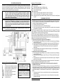
elmes electronic SLIDING GATE AUTOMATION CONTROLLER (230VAC powered) - Elmes STP The controller is designed to use in remote (radio) controlled sliding gate automation system powered by one 230VAC single phase inductive motor capable of moving gate in two directions. It provides the following operating functions and features: Hopping (rolling) code KEELOQ® transmission allowing high level of control command security; Operation with up to 112 Elmes Electronic made 433,92MHz band hand transmitters and/or wired wall switch; Remote control accepting one or two transmitter’s buttons control command; Operation modes: manual, auto-close and two „auto-parking” modes; Auto-close mode with preset PAUSE time (from 1 second up to 4 minutes); Operation with end-of-line switches NO or NC types (normally opened or normally closed at standby); Programmable motor operation time allowing controller use in gate automation without installed endof-line switches; Operation with NC type (normally closed) output Infrared (IR) protective barrier; Auto-open function on IR barrier disturbance while in gate close movement; Gate „STOP” security switch input halting gate’s movement in any direction; Courtesy lamp output – warning (flashing) or steady lighting modes; Separated, auxiliary relay output NO/NC type controlled by additional hand transmitter button; Installation facility function allowing reverse gate movement and reverse end-of-line switches functionality set by jumpers. OPERATION MODES Elmes STP controller operation modes are set by 10pos DIP-Switch placed on controller’s board: JP1 – sets courtesy lamp output operation mode: OFF - flashing warning lamp: flashing slower in gate opening movement and faster in closing movement, ON - lighting lamp – lights steady on gate’s movement; Courtesy lamp output operating mode depends on settings made with JP1 and selected gate operation mode (JP2 & JP3): Gate Operation Mode Warning Lamp Mode (JP1 – OFF) Lighting Lamp Mode (JP1 – ON) Manual Gate opening – flashes slow, Gate closing – Lamp lights in gate movement and JP2 – OFF, JP3 – OFF flashes fast, Sets OFF on gate stop PAUSE time after gate stop All Other Modes G. opening-flashes slow, PAUSE-flashes Lamp lights in gate movement and slow, PAUSE ends–flashes fast, G. clos60 seconds after gate stop ing–flashes fast, G. closed–sets OFF JP2, JP3 – determine the way gate is controlled by hand transmitter or wired wall switch: JP2 - OFF 1. Manual Mode – gate starts moving on transmitter button use. Next use stops the gate. JP3 - OFF Opened gate will not auto-close. Gate closing is made by transmitter button use. JP2 - ON 2. Auto-Close Mode – the use of transmitter button starts gate cycle operation with OPENJP3 - OFF PAUSE-CLOSE steps. The gate can be stopped at any time by transmitter button use. If the gate is fully opened then, after PAUSE time, will auto-close. The use of transmitter button in PAUSE time sets off pause time count and next use of the button closes the gate. JP2 - ON 3. Parking Mode 1 – the use of transmitter button starts gate cycle operation with OPENJP3 - ON PAUSE-CLOSE steps. The use of transmitter button while gate is opening has no effect while in PAUSE mode starts the pause time count again. The use of transmitter button while gate is closing stops the gate and, after 1 second break, starts opening.. In this control mode gate is operated by one transmitter button only (state of JP6 has no meaning). JP2 - OFF 4. Parking Mode 2 (with gate stopping command) – the use of transmitter button starts JP3 - ON gate opening cycle with OPEN-PAUSE-CLOSE steps. The use of transmitter button while gate is moving stops the gate. Next use of transmitter button starts the opening cycle again. The use of transmitter button in PAUSE time stops pause time count and next button use starts PAUSE time count again. In this control mode gate is operated by one transmitter button only (state of JP6 has no meaning). JP4 – limits PAUSE time to 5 seconds on photo-barrier disturbance. IR-barrier disturbance while in PAUSE time stops pause time count. On IR-barrier clearance gate control is resumed in one of two ways, depending on JP4 state: OFF - PAUSE time count is continued if mode 2 (Auto-Close) is selected or, PAUSE time is restarted if mode 3 or 4 are selected; ON - after 5 seconds gate starts closing (in mode 2 only). In control modes 1, 2 & 3 JP4 should be set OFF. JP5 – defines type of used end-of-line switches: OFF - NC type output switches, closed at standby – active when opened; ON - NO type output switches, opened at standby – active when closed; JP6 – defines the way gate is controlled by the use of transmitter buttons (inactive in modes 3 i 4 – see table above): OFF - operates with one transmitter button only in OPEN-STOP-CLOSE-STOP-OPEN… cycle. ON - operates with two transmitter buttons where button one controls OPEN-STOP-OPEN cycle and button two controls CLOSE-STOP-CLOSE… cycle. JP7 – used to reverse directions of gate movement (facilitates controller installation): OFF - controller delivers live phase supply to OPEN terminal at gate opening and to CLOSE terminal at gate closing: ON - reverse: live phase supply is delivered to CLOSE terminal at gate opening and to OPEN terminal at gate closing; JP8 – used to reverse functionality of end-of-line (EOL) switches (facilitates controller installation): OFF - EOL switch KO stops gate opening and EOL switch KC stops gate closing; ON - reverse: EOL switch KO stops gate closing and EOL switch KC stops gate opening; JP9 – flashing of warning courtesy lamp before gate movement: OFF - gate movement and warning flashing of courtesy lamp start simultaneously on hand transmitter or wall switch use; ON - flashing of warning courtesy lamp starts 3 seconds before gate movement; JP10 – reaction on IR-barrier disturbance at gate close movement: OFF - gate stops and starts backwards movement; ON - gate stops; NOTE! When “Parking Mode 1” or “Parking Mode 2” is selected, JP10 should be set to OFF. Infrared-barrier (input FK). IR-barrier disturbance while in gate opening movement has no effect. In closing movement the reaction is described at JP10 setting. The effect of IR-barrier disturbance in PAUSE time is explained at JP4 description. Emergency STOP input. Activation of emergency input STOP stops the gate in opening as well as closing movements. For as long as the input remains activated the gate can not be operated. TECHNICAL SPECIFICATION Controller power supply: mains 230VAC; power draw 4VA maximum. Gate motor relay rating: 2 x NO, 16A/250VAC maximum. Courtesy lamp output: 5A/250VAC maximum. Auxiliary relay output CH2 rating: NO or NC (jumper selected), galvanic separated, 1A/24VDC or 0,5A/125VAC. IR barrier power supply output: 24VDC, 150mA max. polymer fuse protected. IR barrier input NC type (normally closed at standby). Emergency STOP input NC type (normally closed at standby). EOL switches input NC type (normally closed) or NO type (normally opened). Gate motor rotation timing: 1s up to 4 min. – the same in open or close rotation. Auxiliary control output CH2 timing: 0,5s up to 2 min. Gate PAUSE time: 1s up to 4 min. Controller superhet receiver for 434 MHz band. Controller board dimensions: (l/w/h): 95/90/34 mm. Manufacturer’s Limited Warranty: Elmes Electronic products carry two year manufacturer’s warranty as from date of purchase. The warranty is limited to the replacement of faulty original parts or repair defects of improper manufacture. Damage, faulty use or improper handling by the user or installer as well as any changes in product’s hardware or software caused by the user violets the warranty and all due repair costs will be charged. Elmes Electronic shall not be responsible for any damage human or material caused by its products failure to operate correctly. Manufacturer: ELMES ELECTRONIC, 54-611 Wroclaw, Poland ul. Avicenny 2, tel. (+48)717845961, fax: (+48)717845963. Elmes Electronic reserves the right to change product specification without prior notice. KEELOQ® is a registered trademark of Microchip Technology Inc. STP CONTROLLER INSTALLATION The Elmes STP controller is delivered without casing and is intended for direct installation inside gate gear motor shelter housing. Installation should well protect the controller against harsh environmental conditions such as water, high humidity, heat and dust. In order to extend operating range of remote control hand transmitters an external antenna suitable for 434 MHz radio band should be used with its coaxial cable connected to antenna terminals ANT on board of the controller. NOTE! The controller is only a part of automatic gate installation and it is entirely a responsibility of the installer to follow respective EU regulations and standards, in particular compliance with EN 12453, EN 12445, EN12635, EN12604, EN 60204-1, EN60335-1 standards and machinery directive 98/37/WE related to gate automation. Manufacturer of the controller declares compliance of the product with respective EU standards (Manufacturer’s CE Declaration included). CAUTION! Automated sliding gate can cause danger to humans and objects within range of its operation. To avoid accidental injury or damage it is necessary to fit protective photo (infrared) barriers on both sides (recommended) of the gate. Barriers must be installed in such a way as to secure that in no circumstances human or moving object access to moving gate is possible. Barriers installed on both sides of gate should be connected in series. CAUTION! The controller is 230VAC mains powered. Installation with power connected is dangerous and can cause electric shock. Description of STP mains 230VAC connection terminals: L - live phase wire terminal of 23VAC mains cable, N - neutral wire terminal of 230VAC mains cable, PE - ground wire terminal of 230VAC mains cable, PE - ground wire terminal of gate 230VAC motor, OPEN - start-up capacitor terminal , OPEN - open rotation motor phase wire terminal, middle - motor neutral wire terminal , CLOSE - close rotation motor phase wire terminal, CLOSE - start-up capacitor terminal, - courtesy lamp output. NOTICE! Live (phase) wire of mains supply cable MUST be connected to „L” terminal and Neutral wire of mains cable to „N” terminal of the controller. NOTICE! Inputs FK and STOP should be connected to COM, if not used. If EOL switches are not used, inputs KC and KO should be left disconnected with JP5 set ON. Description of STP control terminals: ZFK - infrared barrier supply, (+24V, 150mA max), COM - ground terminal, FK - infrared barrier signal (connect to COM if not used) STOP - gate stop security input (connect to COM if not used), WR - gate control wall switch input, COM - ground terminal, KO - End Of Line open switch, (if EOL switches are not used, set JP5 to ON), KC - End Of Line close switch, (if EOL switches are not used, set JP5 to ON), CH2 - auxiliary relay control output: opened at standby, if jumper „NC NO” is set NO, or closed if jumper is set NC. PROGRAMMING PROCEDURES 1. Learning remote control transmitters to controller’s memory (up to 112 transmitters max.): NOTICE! If the transmitter will be used to control gate operation and auxiliary output CH2, JP1 should be set ON, if gate only - JP1 should be set OFF. After transmitters are learned, the JP1 should be set according to selected operating mode of courtesy lamp. a) Press shortly PRG switch - LED lights on. b) Press selected transmitter button once - PRG LED switches off. c) Press the same transmitter button again. Slowly flashing LED in controller confirms the transmitter is learned and end of procedure. NOTICE! Number of transmitters learned to controller’s memory is limited to 112, learning 113th will remove the first, learning 114th will remove second, etc. Removing lost or stolen transmitter from memory requires deleting all transmitters and learning the remaining ones again. NOTICE! If, while in transmitter learning mode, JP1 was set ON and transmitter button 1 was used, the button will control gate operation while button 2 will control aux. output CH2. In later need to control gate operation with two transmitter buttons (JP6 should be set ON), buttons 1 & 2 would control gate operation while button 3 of the transmitter would control CH2 output. 2. Programming electric tube motor rotation time and PAUSE time: a) Press control unit PRG switch (LED lights on) for more than 2 and less than 8 seconds. Releasing the switch PRG LED sets off. b) Press on hand transmitter button or wired wall switch to start motor rotation (PRG LED lights on). c) When required motor rotation time has lapsed (max. 4 minutes) press the transmitter button (or wired wall switch) again – LED sets OFF and the electric motor stops (if not stopped by EOL switch earlier). d) After required PAUSE time has lapsed press transmitter button again – the PRG LED flashing slowly confirms end of the procedure. 3. Programming set on time of auxiliary output CH2: a) Press control unit PRG switch (LED lights on) for more than 2 and less than 8 seconds. Releasing the switch PRG LED sets off. b) Press transmitter button designated to control CH2 output – LED sets on and the CH2 relay output sets on. c) After required CH2 set on time has lapsed press the same transmitter button again – flashing LED confirms end of the procedure. NOTICE! If time between second and third transmitter button pressing is shorter than 0,5 second then the CH2 output is programmed for bistable operation (set ON – set OFF). 4. Deleting all transmitters in controller’s memory – this procedure should be performed if a transmitter is lost or stolen: Press control unit PRG switch (PRG LED lights on) and hold (over 8 seconds) until PRG LED starts flashing and then release the switch. Flashing LED confirms end of procedure. Transmitter memory in is deleted and controller does not respond to transmitter’s control signals. Programmed motor and CH2 timings remain unchanged. To learn transmitter/s to controller follow pt. 1 of programming procedures. NOTES: 1. Performing procedures 2 & 3 above is possible with wall switch or transmitter already learned to controller’s memory. 2. Gate motor rotation timing is manufacturer set to ca 4 seconds. Required motor timing should be programmed individually. [email protected] www.elmes.pl ©Elmes Electronic 10.2014. All rights reserved.