1
PTZ-35 MS
PTZ-50 MS
Installation and Operation Manual
May 2008
FLIR Systems, Inc.
70 Castilian Drive
Goleta, CA 93117
Phone: 888.747.FLIR (888.747.3547)
International: +1.805.964.9797
427-0016-00-10 Revision 120
http:// www.flir.com
Copyright © 2008 FLIR Systems, Inc.
1
FLIR Systems Inc.
70 Castilian Dr.
Goleta, CA 93117-3027
888.747.FLIR (888.747.3547)
Intl.: +1.805.964.9797
FAX 805 685-2711
www.flir.com
Document Number:
Revision Number:
Date:
427-0016-00-10
120
March, 2008
EXPORT RESTRICTIONS
The information contained in this document may be controlled for export purposes by the
United States Government. Diversion contrary to US law is prohibited. For more
information, contact FLIR Systems, Inc. This document and data disclosed herein or
herewith is not to be reproduced, used, or disclosed in whole or in part to anyone without
the permission of FLIR Systems, Inc.
PROPRIETARY
The data in this publication shall not be disclosed without permission and shall not be
duplicated, used, or disclosed in whole or in part except to the extent provided in any
contract of which this document is made a part. This restriction does not limit the
customer’s right to use information contained in this document if it is obtainable from
another source without restriction. The data subject to this restriction are contained in all
sheets of this document and related drawings and document specifications herein. FLIR
reserves the right to make changes to its products or specifications at any time, without
notice, in order to improve design or performance and to supply the best possible product.
COPYRIGHT
Copyright © 2008 by FLIR Systems, Inc. All rights reserved. This publication, or any parts
thereof, may not be reproduced in any form without the express written permission of FLIR
Systems, Inc.
Pelco is a registered trademark of Pelco. Windows is a registered trademark of Microsoft Corporation.
427-0016-00-10 Revision 120
Copyright © 2008 FLIR Systems, Inc.
2
TABLE OF CONTENTS
1.0 WARNINGS AND CAUTIONS ...................................................................... 5
2.0 INTRODUCTION ........................................................................................... 6
2.1
Advantages of Thermal Imaging......................................................................... 7
2.2
Package Contents .............................................................................................. 8
3.0 QUICK-START INFORMATION.................................................................... 9
4.0 PTZ-35 MS / PTZ-50 MS USER INTERFACE............................................. 10
Communication Panel ................................................................................................. 11
Pan/Tilt Panel .............................................................................................................. 13
Infrared Panel .............................................................................................................. 14
DLTV Panel ................................................................................................................. 16
Manual Control Panel .................................................................................................. 17
5.0 PTZ-35 MS / PTZ-50 MS PHYSICAL INTERFACE .................................... 19
Dimension Drawings ................................................................................................... 19
Integrated Interface Cable Connector ......................................................................... 21
Break-Out Connector Cable ........................................................................................ 22
6.0 MAINTENANCE .......................................................................................... 23
6.1
Lens Cleaning................................................................................................... 23
7.0 PTZ-35 MS / PTZ-50 MS SPECIFICATIONS .............................................. 24
8.0 OPTIONAL JOYSTICK DISPLAY UNIT ..................................................... 26
8.1
Joystick Control w/ Display Unit ....................................................................... 26
Joystick operation........................................................................................................ 26
Joystick drift................................................................................................................. 27
9.0 SOFTWARE CONTROL FUNCTIONS........................................................ 28
9.1
Software Interface Description ......................................................................... 28
9.2
IR Imager.......................................................................................................... 28
9.3
Daylight Camera............................................................................................... 31
9.4
Pan/Tilt Mechanism .......................................................................................... 32
10.0
USER CONTROLS FOR KBD300A ..................................................... 35
427-0016-00-10 Revision 120
Copyright © 2008 FLIR Systems, Inc.
3
TABLE OF FIGURES
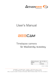
Figure 1: PTZ-35 MS and PTZ-50 MS provide 24/7 threat detection .................................................4
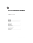
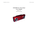
Figure 2: Daylight camera on left; Thermal image on right .................................................................6
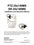
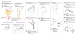
Figure 3: Backlit daylight camera on left; thermal image on right .......................................................7
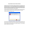
Figure 4: PTZ-35 MS / PTZ-50 MS camera foot and mounting bracket shoe.....................................8
Figure 5: Quick Connect Interface Cable w/ break-out pigtail shown at bottom insert........................9
Figure 6: PTZ-35 MS / PTZ-50 MS User Interface ...........................................................................10
Figure 8: PTZ-35 MS / PTZ-50 MS Communication panel ...............................................................11
Figure 9: PTZ-35 MS / PTZ-50 MS Pan/Tilt panel ............................................................................13
Figure 10: PTZ-35 MS / PTZ-50 MS Infrared panel..........................................................................15
Figure 11: PTZ-35 MS / PTZ-50 MS Infrared panel..........................................................................16
Figure 12: PTZ-35 MS / PTZ-50 MS DLTV panel .............................................................................17
Figure 13: PTZ-35 MS / PTZ-50 MS Manual Control........................................................................18
Figure 14: PTZ-35 MS / PTZ-50 MS Dimension Drawing .................................................................19
Figure 15: PTZ-35 MS / PTZ-50 MS Dimension Drawing with hole pattern......................................20
Figure 16: PTZ-35 MS / PTZ-50 MS Interface Cable Connector ......................................................21
Figure 18: IR Video Output
Figure 19: DLTV video output .........................................................22
Figure 20: RS-232 DB-9 (Female)
Figure 21: RS-422 DB-9 (Male) ...........................................22
Figure 22: Joystick Display Unit........................................................................................................26
Figure 23: Operational Directions on back of Joystick Display Unit..................................................27
Figure 1: PTZ-35 MS and PTZ-50 MS provide 24/7 threat detection
427-0016-00-10 Revision 120
Copyright © 2008 FLIR Systems, Inc.
4
1.0
WARNINGS AND CAUTIONS
Caution! This guide uses the term Caution! to indicate a potentially hazardous situation, which, if
not avoided, may result in bodily harm or injury, damage to the camera, or other property damage.
Protect Your Investment
The enclosure of the PTZ-35 MS and PTZ-50 MS visible camera is pressurized with nitrogen to
eliminate fogging of the camera lens due to sudden changes in temperature.
The camera should be installed by a trained professional according to local codes and industrystandard safe practices.
Proper ESD protocol should be followed while working with the unit.
Do not disassemble the PTZ-35 MS and PTZ-50 MS enclosures. Disassembly can cause
permanent damage and will void the warranty.
Operating the PTZ-35 MS or PTZ-50 MS outside of its specified operating temperature range or
voltage range can cause permanent damage and will void the warranty.
The camera is a precision optical instrument and should not be exposed to excessive shock or
vibration.
When not in use, replace the lens cap over the objective lens. When the lens cap is not in place,
avoid pointing the system directly at extremely high-intensity radiation sources, such as the sun,
lasers, arc welders, etc. This warning applies whether or not the system is powered.
Great care should be used with your camera’s optics. They are delicate and can be damaged by
improper cleaning. Only clean the lens in the manner described in section 6.0 Maintenance.
Legal Considerations
Camera and audio surveillance may be prohibited by laws that vary from country to country. Check
the laws in your local region before using this product for surveillance purposes.
Support
If you have questions that are not covered in this manual, or need service, contact FLIR Customer
Support at (805) 964-9797 for additional information prior to returning your PTZ-35/-50 MS thermal
camera. In the US, you can also reach FLIR Customer Support at (888) 747-FLIR (747-3547).
All thermal imaging systems are subject to export control. Please contact FLIR for export
compliance information concerning your application or geographic area.
427-0016-00-10 Revision 120
Copyright © 2008 FLIR Systems, Inc.
5
2.0
INTRODUCTION
The PTZ-35 MS and PTZ-50 MS are high-resolution multi-sensor camera systems designed
specifically for the security market. These small, pan/tilt systems feature a powerful thermal
camera, with 35mm or 50mm lens, as well as a standard high resolution low-light video camera1,
integrated into a compact weather tight pan and tilt enclosure. The systems can be configured for
portable or point-to-point use, and are compatible with Pelco D protocol (using RS-232 or RS422,
depending on the configuration ordered) and Nexus communications. They are perfect for security
and surveillance applications that demand compact size and rugged performance.
The FLIR system you have purchased includes a sophisticated thermal imaging camera that
provides excellent night visibility and situational awareness, even in absolute darkness. The camera
has a standard video output that works with digital video recording devices, video motion detection
software or off-the-shelf video encoders. Thermal imagers are well suited to video analytics – a
combination of best-in-class intruder detection cameras with intelligent 24-hour automated
monitoring. Day or night, thermal cameras provide excellent scene contrast, critical for highreliability and reduced false alarms, even during daylight hours.
FLIR’s powerful thermal security cameras compliment and complete your security camera network.
They turn night into day, allowing you to see intruders invisible to the naked eye. FLIR PTZ
cameras create video images from infrared thermal energy (heat), and perform well at night and
day, in good weather and bad. The thermal camera system is intended for various commercial and
industrial uses, including security and surveillance applications, such as border / perimeter patrol
and security inspection.
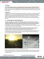
Figure 2: Daylight camera on left; Thermal camera on right
Observe that the image on the left from an ordinary daylight camera is obscured by fog; the thermal
image on the right provides clear details.
The PTZ-35/-50 MS camera is designed for simple, intuitive installation and operation. Each
thermal camera is based on FLIR’s widely-deployed uncooled microbolometer imaging core. All
cameras include FLIR’s advanced image processing techniques which deliver excellent contrast
regardless of scene dynamics.
This camera has a sealed outdoor enclosure that is designed to protect the camera and lens
components in adverse environmental conditions. The sealed enclosure increases the camera
reliability and reduces the cost of maintenance.
1
The standard video camera is referred to in this manual generally as a daylight camera or DLTV.
427-0016-00-10 Revision 120
Copyright © 2008 FLIR Systems, Inc.
6
PTZ-35 MS
The PTZ-35 MS camera features a focal length of 35mm, providing a short to medium field of view
of 20° and is well-suited for short range threat detection in all circumstances. It gives you a wide
field of view, so you can cover a large area and keep excellent situational awareness. Like all FLIR
thermal cameras, the PTZ-35 MS provides crisp, clear thermal imagery in total darkness, haze, light
fog or smoke.
PTZ-50 MS
Utilizing a 50mm lens, the PTZ-50 MS serves as a medium- to long-range surveillance camera and
provides a 14° HFOV. This focal length is widely deployed because it provides an even balance
between situational awareness and detailed perspective. Like the PTZ-35 MS camera, the PTZ-50
MS has a standard resolution focal plane array (FPA) with 320 (H) x 240 (V) pixels, the same
thermal imaging technology found in many of FLIR’s most sophisticated security and surveillance
systems.
2.1 Advantages of Thermal Imaging
Originally developed for the military, thermal imaging cameras are now deployed in numerous
commercial applications where it is impractical or too expensive to use active illumination (lights). It
is perfect for wide-area surveillance in critical infrastructure or high-value residence installations
where lighting is unwelcome or impractical. The camera also provides improved daytime
surveillance in environments where traditional CCTV security camera performance suffers, such as
in shadows, backlit scenes or through foliage.
Low-cost infrared illuminated cameras rely on near infrared (NIR) lamps to illuminate threats,
resulting in shadows, reflections, backscatter, higher power consumption, narrow areas of
illumination and much shorter ranges than passive thermal camera technology.
Unlike other night vision systems that require low amounts of light to generate an image, the PTZ35/-50 MS thermal imagers need no light at all. The choice of lenses for the cameras allow for
short- or medium-range surveillance capability.
Figure 3: Backlit daylight camera on left; thermal camera on right
Observe that the setting sun in the backlit image on the left makes it difficult to discern any objects
of interest; the thermal image on the right is not affected by the bright sun and therefore provides
detail and contrast.
427-0016-00-10 Revision 120
Copyright © 2008 FLIR Systems, Inc.
7
The PTZ-35/-50 MS is designed to be compatible with standard security systems employing
ordinary daylight cameras. A variety of connection options are available. Each system includes a
standard breakout cable that allows connection to power, analog video (one output for the thermal
camera and one for the standard video camera) and control (RS-232 and RS-422 are provided, with
only one or the other useable at any given time, depending on the configuration ordered).
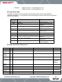
2.2 Package Contents
Refer to the Shipping Check List that is shipped with each camera for a description of the parts and
components that are included with the camera. If there is any discrepancy between the list and the
contents of your shipment, please contact FLIR Systems Customer Support immediately using the
contact information at the front of this manual.
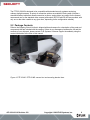
Figure 4: PTZ-35 MS / PTZ-50 MS camera foot and mounting bracket shoe
427-0016-00-10 Revision 120
Copyright © 2008 FLIR Systems, Inc.
8
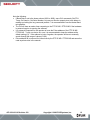
Figure 5: Quick Connect Interface Cable w/ break-out pigtail shown at bottom insert
3.0
QUICK-START INFORMATION
The following instructions will get you started with basic operation of the PTZ-35 MS / PTZ-50 MS.
1. Firmly secure mounting bracket shoe to designated frame or structure able to support and allow
for device travel.
2. Insert camera head foot into the mounting bracket shoe as shown in Figure 4 being careful to
align the pin side of camera head before sliding into shoe. Depress release button on side to fit.
3. Next, tighten tamper resistant set screw to secure camera in place. Screw is shown on far right
side of Figure 4.
4. Remove any lens cap. (Remember to replace the lens cap when the cameras are not in use to
prevent accidental scratching and dust contamination.)
5. Attach the other end of the sealed interface cable to the break-out pigtail.
6. Plug a standard RCA video cable into the connection labeled “DLTV” on the break-out pigtail for
the daylight camera.
7. Plug a standard RCA video cable into the connection labeled “Infrared” on the break-out pigtail
for the infrared camera.
8. If the camera model supports RS-232 communications and you intend to use the User Interface
software for remote control of the device, attach a standard RS-232 cable to the connection
labeled “RS-232” on the break-out pigtail. Connect the other end of the RS-232 cable to an
available COM port slot on the PC. (Be sure to note the COM port number for communication
settings!)
9. Plug the AC/DC converter into an electrical outlet. Insert the circular plug of the power converter
to the connection labeled “POWER” on the break-out pigtail.
10. Now the PTZ-35 MS / PTZ-50 MS camera is ready for use. Note that the device will immediately
zero itself and return back to home position upon applying power.
427-0016-00-10 Revision 120
Copyright © 2008 FLIR Systems, Inc.
9
You have now completed the basic steps for setup of the PTZ-35 MS / PTZ-50 MS. However, it is
recommended that you read the rest of this User’s Manual to learn how to adjust the PTZ-35 MS /
PTZ-50 MS system settings according to your preferences.
4.0
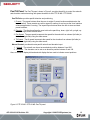
PTZ-35 MS / PTZ-50 MS USER INTERFACE
The User Interface provides the basic pan/tilt control, the infrared camera control and the daylight
camera control as well as communication settings. It also provides an indicator showing read/write
confirmation to the infrared camera after each command in the lower-right corner. Detailed
descriptions for using these controls are described herein.
Figure 6: PTZ-35 MS / PTZ-50 MS User Interface
427-0016-00-10 Revision 120
Copyright © 2008 FLIR Systems, Inc.
10
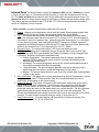
Communication Panel The Communication Panel tab, shown in Figure 6, is located on the
left-side of the About tab. The PTZ-35 MS / PTZ-50 MS can communicate at the 2400, 4800, 9600
& 57600 baud rates and both pan/tilt as well as camera control can be accessed. To access the
device, simply choose the camera control switch and select the correct COM port that is connected
to your PC. Once the correct COM port has been selected then communication can proceed. Note
that selecting the Pelco address will only configure the GUI and not change the device address
itself.
Figure 7: Select COM Port and Pelco Address
If you are having trouble communicating with the device, be sure to check all connections and
confirm the COM port selection at the PC and the device. Also, confirm the standard RS-232 cable
is a working cable and not faulty.
Figure 8: PTZ-35 MS / PTZ-50 MS Communication panel
427-0016-00-10 Revision 120
Copyright © 2008 FLIR Systems, Inc.
11
Note the following:
• If Baud Rate is set to the slower values (2400 or 4800), some GUI commands (Get FPA
Temp, Get Version, Get Serial Number, etc) may not function properly due to the delays in
reading and writing the long command packets. It is recommended to use the fastest baud
rate possible.
• The GUI will have an easier time connecting to the PTZ-35 MS / PTZ-50 MS if the hardware
is powered up prior to opening the software.
• It is extremely important for the operator to know the Pelco address of the PTZ-35 MS /
PTZ-50 MS . If only one device is in use, it is recommended to keep the address at the
default setting (01). If the address is lost or forgotten, the operator will have to manually
search through the range of values (01-99).
• Pelco address 08 is reserved for internal use by the PTZ-35 MS / PTZ-50 MS and cannot be
used anywhere else in the network.
427-0016-00-10 Revision 120
Copyright © 2008 FLIR Systems, Inc.
12
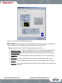
Pan/Tilt Panel The Pan/Tilt panel, shown in Figure 9, provides the ability to control the azimuth
and elevation mechanism along with preset locations for the PTZ-35 MS / PTZ-50 MS.
Pan/Tilt Drive: provides pan/tilt direction and positioning
1. Presets. The preset buttons allow the user to set/get 3 preset locations and determine the
home location. These presets are valid or stored in memory for as long as the User Interface
software application is running. The Import/Export buttons allow the user to store and load
preset locations.
2. Direction. The direction allows the user to drive the pan/tilt up, down, right, left, up-right, upleft, down-right, down-left and home.
3. Pan Speed. The pan speed increments the speed for the azimuth from slowest (left side) to
the fastest (right side) using the slider arrow.
4. Tilt Speed. The tilt speed increments the speed for the elevation from slowest (left side) to
the fastest (right side) using the slider arrow.
Manual Control: provides discrete pan/tilt azimuth and elevation input
1. Azimuth. The azimuth can be set as an absolute position between 0 and 550
2. Elevation. The elevation can be set as an absolute position between 0 and 190
Also, an elevation display dial and azimuth display dial are used to indicate current positions.
Figure 9: PTZ-35 MS / PTZ-50 MS Pan/Tilt panel
427-0016-00-10 Revision 120
Copyright © 2008 FLIR Systems, Inc.
13
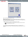
Infrared Panel The Infrared panel contains the Video and AGC tab and a General tab, shown
in Figure 10 and Figure 11. These tabs provide the ability to control the infrared camera from the
PC. The Video and AGC tab provides for basic image optimization along with camera control. The
General tab allows for further camera control to set power-on defaults and get further camera data.
The infrared camera commands for the PTZ-35 MS / PTZ-50 MS software interface are listed in
section 9.0 Software Control Functions.
Video and AGC: provides infrared camera video and AGC settings
1. Polarity. Imagery can be displayed in either white-hot (hotter objects appear brighter than
cooler objects) or black-hot (hotter objects appear darker than cooler objects.
2. FFC. The infrared camera includes an internal shutter for periodically improving image
quality via a process called “flat-field correction” (FFC). During an FFC, a small calibration
flag rotates in front of the detector array, presenting a uniform temperature (i.e. a “flat field”)
to every detector element. Auto mode performs the FFC based on a change in ambient
temperature and Manual mode only performs the FFC when input by the user. Both modes
allows for an instantaneous FCC by depressing the “Do FFC” button.
3. Electronic Zoom. The camera will perform a 2X zoom controlled by the user.
4. AGC Type. The image can be optimized using an Automatic Gain Control or AGC type
algorithm. The three AGC types available are Plateau Equalization, Linear Histogram and
Logarithmic. Definitions for each are described below.
a. Plateau Equalization: The plateau equalization uses a histogram equalization
algorithm (HEQ) to analyze the scene content in real time and redistributes the
dynamic range of the scene.
b. AutoBright: The auto bright algorithm allows for the contrast and brightness bias to
be set while maintaining the offset automatically.
c. Linear Histogram: The linear histogram algorithm uses scene statistics to set a
global linear gain and offset (contrast and brightness) for the image.
d. Manual: The manual setting allows for user control for contrast (gain) and brightness
(offset) for the image.
5. AGC Parameters. The image can be further optimized using the AGC Parameters to control
the Plateau Value, Mid ITT Offset and Max Gain. All of these terms allow the user to
optimize the image based on the scene content.
6. Region Of Interest. The Region Of Interest or ROI determines what portion of the screen
will be used for the AGC calculations. The Full Screen option applies the AGC algorithm
based on scene content on the full screen. The Horizon Optimized applies horizontally
across the screen but uses only the middle third in the vertical direction. The Sky Optimized
applies horizontally across the screen but only the top half in the vertical direction. The
Ground Optimized applies horizontally across the screen but on the lower half in the vertical
direction. The other modes are applied using the center of the screen as 0, 0.
7. Detail Enhancement. This option applies a Bi-Lateral filter to enhance the image. The
default values are 16, 24, 32, 64, 96 and 128.
427-0016-00-10 Revision 120
Copyright © 2008 FLIR Systems, Inc.
14
Figure 10: PTZ-35 MS / PTZ-50 MS Infrared panel
General: provides the user to save the default settings and monitor sensor or FPA temp
1. FPA Temperature. This command gets the FPA or sensor temperature and displays in
degrees C. The FPA Temperature can also be monitored by depressing the “Monitor FPA
Temp?” button.
2. No-Op. The No-Op command sends a non-operational command to the infrared camera.
This can be used to verify camera connectivity.
3. Reset Camera. The Reset Camera command causes the infrared camera to reboot.
4. Set Power-on Defaults. This command will save the image optimization and other settings
into the camera to use upon start-up.
5. Restore Factory Defaults. This command will restore the infrared camera to its factory set
defaults.
6. Array Size. The array size only effects the ROI settings based on either the Photon Block 1
(320x120) or Photon Block 2 (320x240).
7. Get S/N and Get Version. These commands will return the infrared camera serial number
and the software/FPGA versions.
427-0016-00-10 Revision 120
Copyright © 2008 FLIR Systems, Inc.
15
Figure 11: PTZ-35 MS / PTZ-50 MS Infrared panel
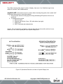
DLTV Panel The DLTV panel contains the daylight camera settings as shown in the Figure 12.
These commands provide the ability to control the daylight camera from the PC.
Zoom: provides the user to control the daylight camera zoom and focus.
1. Optical Zoom In/Out. These commands allow the user to zoom in/out the daylight camera.
2. Digital Zoom On/Off. These commands allow the user to turn on/off the digital zoom.
3. Slow/Fast Slider. This slider allows the user to input the speed of the zoom from slow to
fast.
4. Focus Mode. This command allows for either manual focus or auto focus of the daylight
camera.
5. Focus Near. This command allows the user to focus at objects that are near when in
manual mode.
6. Focus Far. This command allows the user to focus for far away objects when in manual
mode.
7. One-Shot. This command allows the user to auto focus on the objects once with this button
when in manual mode.
427-0016-00-10 Revision 120
Copyright © 2008 FLIR Systems, Inc.
16
Figure 12: PTZ-35 MS / PTZ-50 MS DLTV panel
Manual Control Panel The Manual Control panel, shown in Figure 13, allows the user to
manually send command words to control the pan/tilt, the infrared camera and the daylight camera.
Also, view the system response command word.
Write: provides the user to send hex commands the device for control.
1. Send. Enter the appropriate hex command and this will send the command to the device.
2. Reset. This will reset the entry to all zeros.
A list of commands is in Section 9.0 Software Control Functions. For a complete list of the
commands refer to the PTZ-35 MS / PTZ-50 MS Software Interface Control Document or ICD 1021270-151.
427-0016-00-10 Revision 120
Copyright © 2008 FLIR Systems, Inc.
17
Figure 13: PTZ-35 MS / PTZ-50 MS Manual Control
427-0016-00-10 Revision 120
Copyright © 2008 FLIR Systems, Inc.
18
5.0
PTZ-35 MS / PTZ-50 MS PHYSICAL INTERFACE
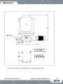
Dimension Drawings The following figures show a dimensional drawing of the PTZ-35 MS /
PTZ-50 MS.
Remember to firmly secure the unit and allow for device travel (pan and tilt).
Figure 14: PTZ-35 MS / PTZ-50 MS Dimension Drawing
427-0016-00-10 Revision 120
Copyright © 2008 FLIR Systems, Inc.
19
Figure 15: PTZ-35 MS / PTZ-50 MS Dimension Drawing with hole pattern
427-0016-00-10 Revision 120
Copyright © 2008 FLIR Systems, Inc.
20
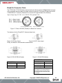
Integrated Interface Cable Connector The PTZ-35 MS / PTZ-50 MS uses an electricalmechanical engagement system that requires only one integrated cable to interface with the sensor.
The interface cable is 12.5 meters (± 0.5) long and is terminated with a MIL-C-26482 Series 1
Connector (Male). The table below describes the specifications:
MIL-C-26482 Series 1
Shell Size
Insert Arrangement
Finish
Contacts
Shell Style
Insert Position
Interface cable connector front view (Male)
18
32
Olive drab
chromate over
cadmium
Pines
Cable plug
Keyring
Chassis connector front view (Female)
Figure 16: PTZ-35 MS / PTZ-50 MS Interface Cable Connector
Function
Power
Pin
Signal Name
j
b
f
h
g
Z
427-0016-00-10 Revision 120
VDC1
VDC1 RTN
VDC2
VDC2 RTN
VDC3
VDC3 RTN
Function
Pin
Signal Name
Comms
N
M
c
A
T
U
S
Video
K
L
H
J
Tx RS-232 (COM1)
Rx RS-232 (COM1)
GND RS-232 (COM1)
Tx (-)RS-422 (COM3)
Rx (-)RS-422 (COM3)
Tx (+)RS-422 (COM3)
Rx (+)RS-422
(COM3)
Video 1
Video 1 Shield
Video 2
Video 2 Shield
Copyright © 2008 FLIR Systems, Inc.
21
Break-Out Connector Cable
The PTZ-35 MS / PTZ-50 MS also include a break-out cable (as shown in Figure 5) that connects
to the integrated interface cable with single terminal connectors. The break-out cable has the MILC-26482 Series 1 Connector (Female) on one end and five pig-tail leads of the following:
Input voltage range: 24 VDC ±10 % with 24 VDC optimum value
Figure 17: Fisher 103-A032 (Female) on Break-Out Connector
Two leads are for the IR and DLTV video as shown here:
Figure 18: IR Video Output
Figure 19: DLTV video output
Finally, two leads for communication as shown here:
Figure 20: RS-232 DB-9 (Female)
Figure 21: RS-422 DB-9 (Male)
RS-422 DB9 Pin
RS-232 DB9 Socket
COM 1 Tx
COM 1 Rx
COM 1 GND
Pin 2
Pin 3
Pin5
427-0016-00-10 Revision 120
COM 3 Tx (+)
Pin 8
COM 3 Tx (-)
Pin 9
COM 3 Rx (+)
Pin 6
COM3 Rx (-)
Pin 7
Note: With RS-422 communications,
the transmit (Tx) connections from
the camera go to the receive (Rx)
connections at the other end, and
vice versa.
Copyright © 2008 FLIR Systems, Inc.
22
6.0
MAINTENANCE
6.1 Lens Cleaning
Materials:
•
•
•
Optical-grade tissue (e.g., Edmund Industrial Optics part number 52105 or any similar
product)
pure water (de-ionized or other)
isopropyl alcohol (IPA)
Procedure:
1. Saturate a piece of the lens tissue with the water and drape it over the lens. Let the surface
tension of the water pull the tissue onto the lens surface and then drag the tissue across the
lens surface. Repeat several times with different pieces of tissue.
2. Repeat the same step using IPA instead of water. Drag the final piece of tissue over the
lens several times to prevent pooling, which could leave a residue behind.
427-0016-00-10 Revision 120
Copyright © 2008 FLIR Systems, Inc.
23
7.0
PTZ-35 MS / PTZ-50 MS SPECIFICATIONS
•
Power/Weight :
Input Voltage Range:
Sensor Weight w/o
cable:
•
Pan/Tilt Specifications:
Motion Range (º)
Angular Velocity
(º/sec)
Resolution (º)
Accuracy (º)
•
•
24 VDC ±10 %
3628 g (8 lbs)
Azimuth
Elevation
± 200
1 to 80
± 60
1 to 40
0.5
1.0, 1σ
0.5
1.0, 1σ
DLTV Camera Specifications:
o
Array >800,000 pixels (PAL) and >680,000 pixels (NTSC)
o
FOV Horizontal 45° to 2°, Optical
o
Focus Automatic
o
Iris Automatic
o
Shutter Automatic
o
Balance Automatic
o
IR cut filter Automatic
o
Image Stabilization 5 to 75 Hz, <1gm.
o
Digital Zoom 12X
o
Spectral Response 400 to 750 nm with IR cut filter
Infrared Camera Specifications:
Wide FOV 30 mm
Focal Plane
Array
Format
Pixel Size
Aperture
Field of View
IFOV
Focus
Temporal NEdT
Range
Uncooled
microbolometer
320 x 240
38µm
f/1.6
23° HFOV x 11° VFOV
1.26 mrad
Manual
50 mK< btw <85 mK
400 meters
o
Frame Rate 30 Hz
o
Spectral Response 7.5µm to 13.5µm
427-0016-00-10 Revision 120
Narrow FOV50 mm
Uncooled
microbolometer
320 x 240
38µm
f/2.0
14° HFOV x 5° VFOV
0.76 mrad
Manual
50 mK< btw <85 mK
700 meters
Copyright © 2008 FLIR Systems, Inc.
24
o
Turn-on time: < 4 sec above -10°C (14°F)
<75 sec at -40°C (-40°F)
•
Image Boresight Requirements – The visible image shall be aligned with the IR image to
within 10% of the equivalent IR FOV.
• Environmental Requirements:
Caution: Sustained storage at high-temperature will degrade vacuum life of the camera core.
o
Storage Temperature -50ºC to +85ºC
o
Operating Temperature -32ºC to + 55ºC
o
Moisture IP-X6
o
Sand/Dust MIL-STD-810E, Method 510.3, procedure II
o
Vibration MIL-STD-810E, Method 514.4
o
Shock (transportation) 30g, 11 msec.
o
EMI/EMC
CE
FCC
o
Solar Thermal Loading MIL-STD-810E, Method 505.3, procedure I, paragraph 1
3.2.b1
o
External Icing MIL-STD-810E, Method 521.1, 6 mm ice thickness
o
Wind Load 35 mph
Note: These specifications are subject to change without notice.
427-0016-00-10 Revision 120
Copyright © 2008 FLIR Systems, Inc.
25
8.0
OPTIONAL JOYSTICK DISPLAY UNIT
8.1 Joystick Control w/ Display Unit
The Joystick Display Unit, also called the LOOK display controller, is shown below in Figure 22.
Figure 22: Joystick Display Unit
The operation directions for the Joystick Display Unit can also be found on the back of unit. An
example of this is shown in Figure 23.
Joystick operation: When pushed left or right, forward (up) or back (down), the camera
moves in that direction. When twisted clockwise, the camera zooms in; zooming in lowers the
pan/tilt speed in three steps. When twisted counterclockwise, the camera zooms out; zooming out
increases the pan/tilt speed. The top two white buttons (GEAR) are used to set the maximum speed
manually.
Low Light Toggle On/Off (DISPLAY) “LO” button the GREEN LED will flash quickly. This mode
applies a slow shutter & the motion will be blurred.
Vibration Press & hold YELLOW 2ND button & press (DISPLAY) “HI” – the top GREEN LED will
flash slowly & the Vibration should decrease.
427-0016-00-10 Revision 120
Copyright © 2008 FLIR Systems, Inc.
26
Tips: When zooming place target in center of display, then zoom. Use “Stabilize Image” when
vehicle is in motion –see Vibration above.
Joystick drift: If the camera moves or zooms without touching the joystick, this is called “drift”.
Follow these instructions to correct the problem:
1. Recycle power without touching joystick during the flashing LED portion of the turn-on
sequence.
2. To recalibrate the joystick:
a. Remove power.
b. Depress and hold the ‘Gear – DN’ white button (top right).
c. Apply power.
d. Wait 10 seconds and release button.
Caution: The unit should be operated by a person other than the driver while vehicle is in use.
When not in use, remove power jack from Joystick Display Unit.
Figure 23: Operational Directions on back of Joystick Display Unit
427-0016-00-10 Revision 120
Copyright © 2008 FLIR Systems, Inc.
27
9.0
SOFTWARE CONTROL FUNCTIONS
9.1 Software Interface Description
The Sensor software interface is accomplished across a single hardware communications channel.
This channel is factory selectable to be either RS-422 or RS-232. The channel baud rate is set at
2400k, 9600k. This channel carries command/status data for all three devices; IR Imager, visible
imager and the pan/tilt mechanism.
The RS-232 configuration is as follows:
Baud Rate
9600
Data Bits
8
Parity
None
Stop Bits
1
Flow Control None
9.2 IR Imager
This section describes the structure of the commands of the IR imager on the PTZ-35 MS / PTZ-50
MS. Note that all data values are called out in hexadecimal. The command and response strings of
the IR imager interface are of variable length, ranging from 10 bytes to 32 bytes. The byte
descriptions are as follows:
Byte 1
Byte 2
Byte 3
Byte 4
Byte 5
Byte 6
Byte 7
Byte 8
Byte
Process Code
Status
Reserved
Function Code
Data Byte Count (MSB)
Data Byte Count (LSB)
CRC 1 (MSB)
CRC 1 (LSB)
Data Byte i (first byte)
…
Byte
Byten
Byten+1
{Variable, 0 to 22 data bytes total}
Data Byte j (last Byte)
CRC 2 (MSB)
CRC 2 (LSB)
where: n = 8 + Data Byte Count
427-0016-00-10 Revision 120
Copyright © 2008 FLIR Systems, Inc.
28
Examples:
If data byte count = 0, total string bytes = 10
If data byte count = 8, total string bytes = 18
IR Imager Status Byte
The status byte (Byte 2) of all commands to the IR Imager should, under normal operating
conditions, contain 00H. For all responses, the thermal imager will set the status byte in accordance
with the following table:
Status Byte
Value (hex)
Definition
Description
0x00
CAM_OK
Function executed
0x01
CAM _BUSY
Camera busy processing serial
command
0x02
CAM _NOT_READY
Camera not ready to execute
specified serial command
0x03
CAM _RANGE_ERROR
Data out of range
0x04
CAM _CHECKSUM_ERROR
Header or message-body
checksum error
0x05
CAM _UNDEFINED_PROCESS_ERROR
Unknown process code
0x06
CAM _UNDEFINED_FUNCTION_ERROR
Unknown function code
0x07
CAM _TIMEOUT_ERROR
Timeout executing serial
command
0x09
CAM _BYTE_COUNT_ERROR
Byte count incorrect for the
function code
0x0A
CAM _FEATURE_NOT_ENABLED
Function code not enabled in the
current configuration.
IR Imager Commands / Responses:
Command Value Command Word
System Response
Notes
No-Op
6E0000000000DFBB0000
6E0000000000DFBB0000
Set Camera
Defaults
6E0000010000EB8B0000
6E0000010000EB8B0000
Reset
Factory
Defaults
6E000003000086EB0000
6E000003000086EB0000
Get Serial
Number
6E0000650000AF200000
6E0000650004EFA4000(aabbccdd)0E
S/N aabbccdd
Get Version
6E0000050000344B0000
6E0000050008B543(abcdefghijklmnop)0DF7
Software
ab.cd.ef.gh
FPGA
ij.kl.mn.op
Auto
6E00000B00020F0800000000
6E00000B00020F0800000000
Manual
6E00000B00020F0800011022
6E00000B00020F0800011022
Set FFC
Mode
Do FFC
6E00000C0000AADA0000
E-Zoom
1x
6E00000F0002D3C800000000
427-0016-00-10 Revision 120
6E00000F0002D3C800000000
Copyright © 2008 FLIR Systems, Inc.
29
2x
6E00000F0002D3C800044084
6E00000F0002D3C800044084
White-Hot
6E0000100002BC9A00000000
6E0000100002BC9A00000000
Black-Hot
6E0000100002BC9A00011021
6E0000100002BC9A00011021
Plateau
Equalization
6E0000130002E5CA00000000
6E0000130002E5CA00000000
Linear
Histogram
6E0000130002E5CA000550A5
6E0000130002E5CA000550A5
6E0000130002E5CA000660C6
6E0000130002E5CA000660C6
Command Word
System Response
Notes
6E0000200002793F00000000
6E0000200002793F(abcd)XXXX
ab cd Hex Deg
C XXXX is
CRC 2
Open
6E0000790002B96000000000
6E0000790002B96000000000
Closed
6E0000790002B96000011021
6E0000790002B96000011021
Video
Polarity
AGC Type
Logarithmic
Command
Get FPA
Temp
Value
Shutter
Position
Set Max Gain
2 6E00006A0002A3529302202
6E00006A0002A3529302202
3 6E00006A0002A35300033063
6E00006A0002A35300033063
4 6E00006A0002A35300044084
6E00006A0002A35300044084
5 6E00006A0002A353000550A5
6E00006A0002A353000550A5
6 6E00006A0002A3530660C6
6E00006A0002A3530660C6
7 6E00006A0002A35000770E7
6E00006A0002A35000770E7
8 6E00006A0002A3500088108
6E00006A0002A3500088108
9 6E00006A0002A35300099129
6E00006A0002A35300099129
10 6E00006A0002A353000BB16B
6E00006A0002A353000BB16B
11 6E00006A0002A353000CC18C
6E00006A0002A353000CC18C
12 6E00006A0002A353000DD1AD
6E00006A0002A353000DD1AD
13 6E00006A0002A353000EE1CE
6E00006A0002A353000EE1CE
14 6E00006A0002A353000FF1EF
6E00006A0002A353000FF1EF
15 6E00006A0002A35300101231
6E00006A0002A35300101231
Set ROI Size
Full Screen
6E00004C0008367FFF60FFC400A0003C8317
6E00004C0008367FFF60FFC400A0003C8317
Horizon
Optimized
6E00004C0008367FFF60FFE200A0001E4206
6E00004C0008367FFF60FFE200A0001E4206
Sky
Optimized
6E00004C0008367FFF60FFC400A0000074C8
6E00004C0008367FFF60FFC400A0000074C8
Ground
Optimized
6E00004C0008367FFF60000000A0003C6D16
6E00004C0008367FFF60000000A0003C6D16
Center 75%
6E00004C0008367FFF88FFD30078002DA5F2
6E00004C0008367FFF88FFD30078002DA5F2
Center 50%
6E00004C0008367FFFB0FFE20050001EE03A
6E00004C0008367FFFB0FFE20050001EE03A
Center 25%
6E00004C0008367FFFD8FFF10028000F59BC
6E00004C0008367FFFD8FFF10028000F59BC
Set Detail
Enhancemen
t
10 6E0000D30008627700003090106400043967
427-0016-00-10 Revision 120
6E0000D30000E37F0000
Copyright © 2008 FLIR Systems, Inc.
30
20 6E0000D3000862770000309020640004158E
6E0000D30000E37F0001
30 6E0000D300086277000030903064000422C0
6E0000D30000E37F0002
Photon
Reboot
6E0000020000B1DB0000
6E0000020000B1DB0000
Plateau
Value
0
Command
100 6E00003F0002166D00000000
6E00003F0002166D00000000
200 6E00003F0002166D00642C22
6E00003F0002166D00642C22
300 6E00003F0002166D00C85844
6E00003F0002166D00C85844
400 6E00003F0002166D012CDFD6
6E00003F0002166D012CDFD6
500 6E00003F0002166D0190B088
6E00003F0002166D0190B088
600 6E00003F0002166D0258BD9F
6E00003F0002166D0258BD9F
700 6E00003F0002166D02BC0035
6E00003F0002166D02BC0035
800 6E00003F0002166D03207131
6E00003F0002166D03207131
900 6E00003F0002166D0384845F
6E00003F0002166D0384845F
1000 6E00003F0002166D03E82975
6E00003F0002166D03E82975
Value
Command Word
System Response
Notes
Mid ITT
Offset
10 6E00005500024AC7000AA14A
6E00005500024AC7000AA14A
20 6E00005500024AC7001452B5
6E00005500024AC7001452B5
30 6E00005500024AC7001EF3FF
6E00005500024AC7001EF3FF
40 6E00005500024AC70028A56A
6E00005500024AC70028A56A
50 6E00005500024AC700321611
6E00005500024AC700321611
60 6E00005500024AC7003CF7DF
6E00005500024AC7003CF7DF
70 6E00005500024AC700462802
6E00005500024AC700462802
80 6E00005500024AC700505AF5
6E00005500024AC700505AF5
90 6E00005500024AC7005AFBBF
6E00005500024AC7005AFBBF
100 6E00005500024AC700642C22
6E00005500024AC700642C22
110 6E00005500024AC7006E8D68
6E00005500024AC7006E8D68
125 6E00005500024AC7007DAF3A
6E00005500024AC7007DAF3A
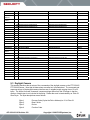
9.3 Daylight Camera
This section describes the structure of the commands of the daylight camera on the PTZ-35 MS /
PTZ-50 MS Sensor. Note that all data values are called out in hexadecimal. The command and
response strings of the daylight camera interface are of variable length, ranging from of 5 to 32
bytes. The format for these command / response strings differs from the IR Imager in that the
number of data bytes is not included in the string. Rather the word is terminated by an “End-OfWord” byte. The byte descriptions are as follows:
Byte 1
Byte 2
Byte 3
Byte 4
427-0016-00-10 Revision 120
Process Code (8 plus the Pelco Address) ie. 81 is Pelco 01
Read / Write
Device
Function Code
Copyright © 2008 FLIR Systems, Inc.
31
Byte
Byte
Byten
Data Byte i (first byte)
…
{Variable, 0 to 27 data bytes total}
Data Byte j (last Byte)
End Of Word
where: n = 5 + Number of Data Bytes
Visible Imager Commands/Responses:
Command
Command Word
System Response
Notes
In
81 01 04 07 2Z FF
90 41 FF 90 51 FF
Z=Speed, 2-7
Out
81 01 04 07 3Z FF
90 41 FF 90 51 FF
Stop
81 01 04 07 00 FF
90 41 FF 90 51 FF
81 09 04 47 FF
90 50 0Z 0Z 0Z 0Z FF
ZZZZ = Position
LSB = 0.5 deg.
Z=Speed, 2-7
Zoom
Get Zoom Position
Focus
Near
81 01 04 08 2Z FF
90 41 FF 90 51 FF
Far
81 01 04 08 3Z FF
90 41 FF 90 51 FF
Stop
81 01 04 08 00 FF
90 41 FF 90 51 FF
Auto
81 01 04 38 02 FF
90 41 FF 90 51 FF
Focus
81 01 04 38 03 FF
90 41 FF 90 51 FF
One-Shot Focus
Manual
81 01 04 18 01 FF
90 41 FF 90 51 FF
Get Focus Position
81 09 04 48 FF
90 50 0Z 0Z 0Z 0Z FF
ZZZZ = Position
LSB = 0.5 deg.
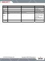
9.4 Pan/Tilt Mechanism
This section describes the structure of the commands for the Pan/Tilt on the PTZ-35 MS / PTZ-50
MS Sensor. Note that all data values are called out in hexadecimal. The command and response
strings of the Pan / Tilt Mechanism interface are of variable length, ranging from 5 to 32 bytes. The
format for these command / response strings differs from the IR Imager in that the number of data
bytes is not included in the string. Rather the word is terminated by an “End-Of-Word” byte. The
byte descriptions are as follows:
Byte 1
Byte 2
Byte 3
Byte 4
Byte
Byte
Byten
427-0016-00-10 Revision 120
Process Code (8 plus the Pelco Address) ie. 81 is Pelco 01
Read / Write
Device
Function Code
Data Byte i (first byte)
…
{Variable, 0 to 27 data bytes total}
Data Byte j (last Byte)
End Of Word
Copyright © 2008 FLIR Systems, Inc.
32
where: n = 5 + Number of Data Bytes
Pan/Tilt Commands/Responses
Command
Command Word
System Response
Notes
Up
81010601VVWW030 FF
90 41 FF 90 51 FF
VV=Pan Speed, 0 to FEH,
FEH = fastest
WW=Tilt Speed, 0 to FEH,
FEH = fastest
Min value = 28H typical
Down
81010601VVWW0302FF
90 41 FF 90 51 FF
VV=Pan Speed, 0 to FEH,
FEH = fastest
WW=Tilt Speed, 0 to FEH,
FEH = fastest
Min value = 28H typical
Left
81010601VVWW0103 FF
90 41 FF 90 51 FF
VV=Pan Speed, 0 to FEH,
FEH = fastest
WW=Tilt Speed, 0 to FEH,
FEH = fastest
Min value = 28H typical
Right
81010601VVWW0203 FF
90 41 FF 90 51 FF
VV=Pan Speed, 0 to FEH,
FEH = fastest
WW=Tilt Speed, 0 to FEH,
FEH = fastest
Min value = 28H typical
Up Left
81010601VVWW0101 FF
90 41 FF 90 51 FF
VV=Pan Speed, 0 to FEH,
FEH = fastest
WW=Tilt Speed, 0 to FEH,
FEH = fastest
Min value = 28H typical
Up Right
81010601VVWW0201 FF
90 41 FF 90 51 FF
VV=Pan Speed, 0 to FEH,
FEH = fastest
WW=Tilt Speed, 0 to FEH,
FEH = fastest
Min value = 28H typical
Down Left
81010601VVWW0102 FF
90 41 FF 90 51 FF
VV=Pan Speed, 0 to FEH,
FEH = fastest
WW=Tilt Speed, 0 to FEH,
FEH = fastest
Min value = 28H typical
Down Right
81010601VVWW0202 FF
90 41 FF 90 51 FF
VV=Pan Speed, 0 to FEH,
FEH = fastest
WW=Tilt Speed, 0 to FEH,
FEH = fastest
Min value = 28H typical
Stop
81010601VVWW0303 FF
90 41 FF 90 51 FF
427-0016-00-10 Revision 120
Copyright © 2008 FLIR Systems, Inc.
33
Home
Goto
80 01 06 04 03 FF
90 41 FF 90 51 FF
Go to Home Position
Set
81 01 06 04 02 FF
90 41 FF 90 51 FF
Set Home position to current
P/T position
81 09 06 12 FF
90 50 0P0Q 0R 0S 0T 0U 0V 0W 0V 0W FF
PQR.S=Pan, TUV.W=Tilt,
HEX, LSB=1/2deg
81 01 06 02 GG HH 0a 0b 0c 0d 0e 0f 0g
0h FF
90 41 FF 90 51 FF
PQRS=Pan Posit., PQR.SH
°
TUVW=Tilt Posit., TUV.WH °
example 135.5 = 00 08 07
08, LSB=1/2°
GG=Pan Speed, 00H to
18H, 18H= 86 deg/s, 00H=5
deg/s
90 41 FF 90 51 FF
HH= Tilt Speed
Get Pan/Tilt
Position
Presets
Go To
(Absolute
Position)
Set (Current
Position)
427-0016-00-10 Revision 120
Copyright © 2008 FLIR Systems, Inc.
34
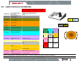
10.0
USER CONTROLS FOR KBD300A
To start type Pelco Address then CAM
CW
Joystick
CCW
Joystick
PTZ-35 MS / PTZ-50
MS Function
Increments DLTV
Focus closer
Increments DLTV
Focus farther
Increments DLTV
Zoom closer
Increments DLTV
Zoom farther
1, Aux On
IR Polarity to Black Hot
1, Aux Off
IR Polarity to White
Hot
2, Aux On
Set IR to 2X ezoom
2, Aux Off
Set IR to 1X ezoom
3, Aux On
Toggle: Plateau Values
250, 300, 400, 50, 150, 200
3, Aux Off
Toggle: AGC Type
Plateau, AutoBright, Linear, Plateau,
AutoBright, Linear
4, Aux Off
IR FFC
5, Aux Off
Toggle: LUT Palette
6, Aux On
Toggle: DDE gain in
photon
32, 64, 96, 128, 16, 24
6, Aux Off
Toggle: AGC ROI
Full,Horizon, Sky, Ground, Center,
Center(smaller)
7, Aux On
Toggle:MID ITT in
Photon
140, 160, 200, 60, 100, 120
7, Aux Off
Toggle: Max gain value
8, 10, 12, 2, 4, 6
Keystrokes
Near button
Far button
Toggle Values (default to first
value)
AUX
ON
NEAR
White, Black, Sepia, Color1, FireIce,
Rain
1
2
3
4
5
6
7
8
9
CAM
0
CLEAR
Note: If communication unsuccessful either type 0,1 CAM or disconnect and then reconnect the keyboard
427-0016-00-10 Revision 100
Copyright © 2008 FLIR Systems, Inc.
35
FAR
AUX
OFF