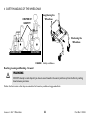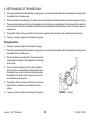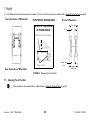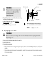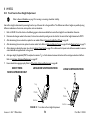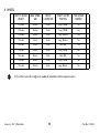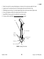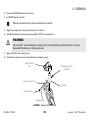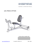
1
Invacare® A-4® Wheelchair User Manual This manual MUST be given to the user of the product. BEFORE using this product, read this manual and save for future reference. EN © 2010 Invacare Corporation. All rights reserved. Republication, duplication or modification in whole or in part is prohibited without prior written permission from Invacare. Trademarks are identified by ™ and ®. All trademarks are owned by or licensed to Invacare Corporation or its subsidiaries unless otherwise noted. Natural Fit is a registered trademark of Three Rivers. Spinergy is a registered trademark of Spinergy, Inc. 3-in-1 oil is a registered trademark of American Home Products Corporation. WD-40 is a registered trademark of WD-40 Company. Loctite 242 is a trademark of the Loctite Corporation. Teflon is a registered trademark of E.I. Du Pont De Nemours and Company. Schwalbe is a registered trademark of Ralf Bohle Gmbh & Co. KG Corporation, Germany. Invacare® A-4® Wheelchair 2 Part No 1110545 CONTENTS 1 GENERAL 7 2 Symbols .................................................................................................................................................................................................................................................... 7 Limited Warranty .................................................................................................................................................................................................................................. 8 SAFETY 9 3 General Guidelines ................................................................................................................................................................................................................................ 9 OVERVIEW 15 4 Label Locations..................................................................................................................................................................................................................................... 15 Component Identification .................................................................................................................................................................................................................. 16 Typical Product Parameters .............................................................................................................................................................................................................. 17 SAFETY/HANDLING OF THE WHEELCHAIR 20 5 Safety/Handling of the Wheelchair .................................................................................................................................................................................................. 20 Stability and Balance ............................................................................................................................................................................................................................ 20 Coping with Everyday Obstacles...................................................................................................................................................................................................... 23 A Note to Wheelchair Assistants.................................................................................................................................................................................................... 23 Tipping .................................................................................................................................................................................................................................................... 24 Tipping - Curbs..................................................................................................................................................................................................................................... 24 Stairways ................................................................................................................................................................................................................................................ 25 Escalators ............................................................................................................................................................................................................................................... 27 Transferring To and From Other Seats.......................................................................................................................................................................................... 27 SAFETY INSPECTION 28 Safety Inspection Checklist ................................................................................................................................................................................................................ 28 Troubleshooting................................................................................................................................................................................................................................... 31 Maintenance .......................................................................................................................................................................................................................................... 31 Part No 1110545 3 Invacare® A-4® Wheelchair CONTENTS 6 UPHOLSTERY 34 7 Removing/Installing Standard Back Upholstery............................................................................................................................................................................. 34 Adjustable Tension Back Upholstery .............................................................................................................................................................................................. 35 Removing/Installing Adjustable Tension Back Upholstery.......................................................................................................................................................... 36 Seat Upholstery Replacement........................................................................................................................................................................................................... 37 Unfolding/Folding the Back ................................................................................................................................................................................................................ 38 FRAME 40 8 Back Angle Adjustment ...................................................................................................................................................................................................................... 40 Back Height Adjustment..................................................................................................................................................................................................................... 42 Rear Seat-to-Floor Height Adjustment........................................................................................................................................................................................... 43 Replacing Seat Frame .......................................................................................................................................................................................................................... 44 Opening/Closing Camber Clamps.................................................................................................................................................................................................... 46 Determining Toe In/Toe Out. .......................................................................................................................................................................................................... 47 Adjusting Toe In/Toe Out ................................................................................................................................................................................................................. 48 Axle Tube Positioning For 0°/3°, 0°/6°, 3°/6° or 9°/12° Camber Inserts .............................................................................................................................. 49 Axle Tube Positioning for 0°/9°, 0°/12°, 3°/9°, 6°/9°, 3°/12° or 6°/12° Camber Inserts ................................................................................................... 49 Adjusting The Axle Tube. .................................................................................................................................................................................................................. 52 Repositioning Camber Inserts (Adjusting Rear Wheel Camber). ............................................................................................................................................ 54 Adjusting Wheelbase Length (Adjusting Center Of Gravity).................................................................................................................................................... 56 Adjusting Wheelbase Width ............................................................................................................................................................................................................. 59 Replacing Axle Tube............................................................................................................................................................................................................................ 60 WHEELS 63 Removing/Installing Rear Wheels..................................................................................................................................................................................................... 63 Adjusting Quick- Release Axle ......................................................................................................................................................................................................... 64 Installing Quad-release Axle.............................................................................................................................................................................................................. 64 Invacare® A-4® Wheelchair 4 Part No 1110545 CONTENTS 9 Adjusting The Quad-release Handle ............................................................................................................................................................................................... 65 Removing The Play From The Rear Wheels ................................................................................................................................................................................. 66 Handrim Replacement ........................................................................................................................................................................................................................ 67 Wheel Lock Adjustment/Replacement ........................................................................................................................................................................................... 68 Replacing/Adjusting Casters .............................................................................................................................................................................................................. 69 Replacing Forks..................................................................................................................................................................................................................................... 71 Adjusting Caster Height ..................................................................................................................................................................................................................... 72 Adjusting Front Seat-To-Floor Height ............................................................................................................................................................................................ 73 Determining Frame Size ..................................................................................................................................................................................................................... 73 Front Seat-to-floor Height Adjustment .......................................................................................................................................................................................... 74 FOOTREST 85 Replacing the Footrest........................................................................................................................................................................................................................ 85 Footplate Angle Adjustment.............................................................................................................................................................................................................. 85 Footplate Depth Adjustment ............................................................................................................................................................................................................ 85 10 ANTI-TIPPER 87 Anti-tipper Adjustment/Replacement ............................................................................................................................................................................................. 87 Anti-tipper Adjustment....................................................................................................................................................................................................................... 87 Anti-tipper Replacement .................................................................................................................................................................................................................... 88 11 ARMS 90 Installing The T-arm Sockets............................................................................................................................................................................................................. 90 Installing/Removing T-arms................................................................................................................................................................................................................ 91 Adjusting The T- Arms ....................................................................................................................................................................................................................... 92 Adjusting T-Arm Sockets ................................................................................................................................................................................................................... 94 Adjusting T-arm Transfer Assists and/or Side Guards................................................................................................................................................................ 96 Replacing T-arm Locking Lever ........................................................................................................................................................................................................ 96 Part No 1110545 5 Invacare® A-4® Wheelchair CONTENTS Installing The Half Arm Socket ......................................................................................................................................................................................................... 98 Adjusting Half Arm Height...............................................................................................................................................................................................................100 12 SUSPENSION 101 Elastomers And Suspension.............................................................................................................................................................................................................101 Replacing Rear Elastomers...............................................................................................................................................................................................................101 Replacing Front Elastomers .............................................................................................................................................................................................................102 Invacare® A-4® Wheelchair 6 Part No 1110545 1 GENERAL 1 General 1.1 Symbols Warnings Signal words are used in this manual and apply to hazards or unsafe practices which could result in personal injury or property damage. See the information below for definitions of the signal words. DANGER WARNING CAUTION ! Danger indicates an imminently hazardous situation which, if not avoided, will result in death or serious injury. Warning indicates a potentially hazardous situation which, if not avoided, could result in death or serious injury. Caution indicates a potentially hazardous situation which, if not avoided, may result in property damage or minor injury or both. IMPORTANT Indicates a hazardous situation that could result in damage to property if it is not avoided. Gives useful tips, recommendations and information for efficient, trouble-free use. Part No 1110545 7 Invacare® A-4® Wheelchair 1 GENERAL 1.2 Limited Warranty PLEASE NOTE: THE WARRANTY BELOW HAS BEEN DRAFTED TO COMPLY WITH FEDERAL LAW APPLICABLE TO PRODUCTS MANUFACTURED AFTER JULY 4, 1975. This warranty is extended only to the original purchaser/user of our products. This warranty gives you specific legal rights and you may also have other legal rights which vary from state to state. Invacare warrants the frame to be free from defects in materials and workmanship for a lifetime from date of purchase; all remaining components for one (1) year from date of purchase except upholstered materials, padded materials and tires/wheels. If within such warranty period any such product shall be proven to be defective, such product shall be repaired or replaced at Invacare's option. This warranty does not include any labor or shipping charges incurred in replacement part installation or repair of any such product. Invacare’s sole obligation and your exclusive remedy under this warranty shall be limited to such repair and/or replacement. For warranty service, please contact the dealer from whom you purchased your Invacare product. In the event you do not receive satisfactory warranty service, please write directly to Invacare at the address below, provide dealer’s name, address, and the date of purchase, indicate nature of the defect and, if the product is serialized, indicate the serial number. Do not return products to our factory without our prior consent. Limitations and Exclusions: The foregoing warranty shall not apply to serial numbered products if the serial number has been removed or defaced, products subjected to negligence, accident, improper operation, maintenance or storage, products modified without Invacare’s express written consent including, but not limited to, modification through the use of unauthorized parts or attachments; products damaged by reason of repairs made to any component without the specific consent of Invacare, or to a product damaged by circumstances beyond Invacare’s control, and such evaluation will be solely determined by Invacare. The warranty shall not apply to problems arising from normal wear or failure to adhere to these instructions. THE FOREGOING EXPRESS WARRANTY IS EXCLUSIVE AND IN LIEU OF ANY OTHER WARRANTIES WHATSOEVER, WHETHER EXPRESS OR IMPLIED, INCLUDING THE IMPLIED WARRANTIES OF MERCHANTABILITY AND FITNESS FOR A PARTICULAR PURPOSE, AND THE SOLE REMEDY FOR VIOLATIONS OF ANY WARRANTY WHATSOEVER, SHALL BE LIMITED TO REPAIR OR REPLACEMENT OF THE DEFECTIVE PRODUCT PURSUANT TO THE TERMS CONTAINED HEREIN. THE APPLICATION OF ANY IMPLIED WARRANTY WHATSOEVER SHALL NOT EXTEND BEYOND THE DURATION OF THE EXPRESS WARRANTY PROVIDED HEREIN. INVACARE SHALL NOT BE LIABLE FOR ANY CONSEQUENTIAL OR INCIDENTAL DAMAGES WHATSOEVER. THIS WARRANTY SHALL BE EXTENDED TO COMPLY WITH STATE/PROVINCIAL LAWS AND REQUIREMENTS. Invacare® A-4® Wheelchair 8 Part No 1110545 2 SAFETY 2 Safety The safety section contains important information for the safe operation and use of this product. 2.1 WARNING After and adjustments, repair or service and before use, make sure all attachment hardware is tightened securely - otherwise, injury or damage may result. General Guidelines ! WARNING DO NOT use this product or any available optional equipment without first completely reading and understanding these instructions and any additional instructional material such as owner’s manuals, service manuals or instruction sheets supplied with this product or optional equipment. If you are unable to understand the warnings, cautions or instructions, contact a healthcare professional, dealer or technical personnel before attempting to use this equipment - otherwise, injury or damage may occur. ACCESSORIES WARNINGS Invacare products are specifically designed and manufactured for use in conjunction with Invacare accessories. Accessories designed by other manufacturers have not been tested by Invacare and are not recommended for use with Invacare products. NOTICE THE INFORMATION CONTAINED IN THIS DOCUMENT IS SUBJECT TO CHANGE WITHOUT NOTICE. Check all parts for shipping damage and test before using. In case of damage, DO NOT use. Contact Invacare/Carrier for further instruction. Part No 1110545 9 Invacare® A-4® Wheelchair 2 SAFETY WARNING Wheelchair User As a manufacturer of wheelchairs, Invacare endeavors to supply a wide variety of wheelchairs to meet many needs of the end user. However, final selection of the type of wheelchair to be used by an individual rests solely with the user and his/her healthcare professional capable of making such a selection. Wheelchair Tie Down Restraints Invacare recommends that wheelchair users not be transported in vehicles of any kind while in wheelchairs. As of this date, the Department of Transportation has not approved any tie-down systems for transportation of a user while in a wheelchair, in a moving vehicle of any type. It is Invacare’s position that users of wheelchairs should be transferred into appropriate seating in vehicles for transportation and use be made of the restraints made available by the auto industry. Invacare cannot and does not recommend any wheelchair transportation systems. Stability The position of the footrest, seat angle, back angle, seating system/upholstery, caster size and position, rear wheel size and position, use of anti-tippers, as well as the user condition directly relate to the stability of the wheelchair. Any change to one or any combination of the ten may cause the wheelchair to decrease in stability. EXTREME care must be taken when changing the stability of the wheelchair. To maintain maximum stability, the rear wheels should be left in the factory setting. Moving the rear wheels forward causes the wheelchair to decrease in stability. ALWAYS ensure stability before moving the rear wheels forward. Test wheelchair before it is occupied by the end user to ensure safety. Invacare® A-4® Wheelchair 10 Part No 1110545 ✓ ● ✓ ✓ N/A N/A N/A N/A N/A ✓ BACK ANGLE N/A ✓ ● ✓ N/A N/A N/A N/A N/A ✓ ✓ ✓ ✓ ● N/A N/A N/A N/A N/A ✓ SEATING SYSTEM/UPHOLSTERY N/A N/A N/A N/A N/A N/A ✓ ✓ ✓ ✓ N/A ● ✓ ✓ ✓ ✓ N/A ✓ ✓ ● ✓ ✓ ✓ N/A ✓ ✓ ✓ ● ✓ ✓ N/A ✓ ✓ ✓ ✓ ● ✓ ✓ ✓ ✓ ✓ ✓ ✓ N/A N/A N/A CASTER POSITION N/A N/A N/A N/A REAR WHEEL SIZE N/A N/A N/A REAR WHEEL POSITION N/A N/A N/A ANTI-TIPPERS N/A N/A N/A N/A Part No 1110545 ✓ 11 ✓ ✓ ✓ ✓ ● CASTER SIZE USER CONDITION USER CONDITION SEAT ANGLE ANTI-TIPPERS ✓ REAR WHEEL SIZE ✓ CASTER POSITION BACK ANGLE ● When changes to the left hand column occur, follow across the chart and refer to the ✓ procedure to maintain the proper stability, safety and handling of the wheelchair. CASTER SIZE SEAT ANGLE FOOTREST POSITION SEATING SYSTEM FOOTREST POSITION REAR WHEEL POSITION 2 SAFETY ✓ Invacare® A-4® Wheelchair 2 SAFETY NOTE: Additional adjustments may be needed according to the wheelchair type. Refer to the wheelchair owner’s manual for these procedures. WARNING Repair and Service Information Unless otherwise noted, all service and adjustments should be performed while the wheelchair is unoccupied. Operating Information To determine and establish your particular safety limits, practice bending, reaching and transferring activities in several combinations in the presence of a qualified healthcare professional before attempting active use of the wheelchair. DO NOT attempt to reach objects if you have to move forward in the seat. DO NOT attempt to reach objects if you have to pick them up from the floor by reaching down between your knees. DO NOT lean over the top of the back upholstery to reach objects from behind as this may cause the wheelchair to tip over. DO NOT shift your weight or sitting position toward the direction you are reaching as the wheelchair may tip over. DO NOT tip the wheelchair without assistance. DO NOT attempt to stop a moving wheelchair with wheel locks. Wheel locks are not brakes. Never leave an unoccupied wheelchair on an incline. DO NOT use an escalator to move a wheelchair between floors. Serious bodily injury may occur. DO NOT operate on roads, streets or highways. DO NOT climb, go up or down ramps or traverse slopes greater than 9°. DO NOT attempt to move up or down an incline with a water, ice or oil film. DO NOT attempt to ride over curbs or obstacles. Doing so may cause your wheelchair to turn over and cause bodily harm or damage to the wheelchair. DO NOT attempt to lift the wheelchair by any removable (detachable) parts. Lifting by means of any removable (detachable) parts of a wheelchair may result in injury to the user or damage to the wheelchair. DO NOT stand on the frame of the wheelchair. ALWAYS keep hands and fingers clear of moving parts to avoid injury. Invacare® A-4® Wheelchair 12 Part No 1110545 2 SAFETY WARNING Check all Allen screws that secure the footrest/raised footrest system to the wheelchair frame before using the wheelchair, especially if engaging in any contact sport. Anti-tippers MUST be used at all times. When outdoors on wet, soft ground or on gravel surfaces, anti-tippers may not provide the same level of protection against tip over. Extra caution MUST be observed when traversing such surfaces. Inasmuch as the anti-tippers are an option on this wheelchair (you may order with or without the anti-tippers), Invacare strongly recommends ordering the anti-tippers as an additional safeguard for the wheelchair user. Engaging the wheel locks may not prevent the wheelchair from moving on all floor surfaces including those that may be wet or slick. ALWAYS exercise caution when transferring into or out of the wheelchair. ALWAYS use the handrims for self-propulsion. Inasmuch as the handrims are an option on this wheelchair (you may order with or without the handrims), Invacare strongly recommends ordering the handrims as an additional safeguard for the wheelchair user. DO NOT use the footplate as a platform when getting in or out of the wheelchair. Seat Positioning Straps ALWAYS wear your seat positioning strap. Inasmuch as the seat positioning strap is an option on this wheelchair (you may order with or without the seat positioning strap), Invacare strongly recommends ordering the seat positioning strap as an additional safeguard for the wheelchair user. The seat positioning strap is a positioning strap only. It is not designed for use as a safety device withstanding high stress loads such as auto or aircraft safety belts. If signs of wear appear, strap MUST be replaced IMMEDIATELY. With regards to seat/chest positioning straps - it is the obligation of the DME dealer, therapists and other healthcare professionals to determine if a seat/chest positioning strap is required to ensure the safe operation of this equipment by the user. Serious injury can occur in the event of a fall from a wheelchair. Tire Pressure and Information DO NOT use your wheelchair unless it has the proper tire pressure (p.s.i.). DO NOT overinflate the tires. Failure to follow these suggestions may cause the tire to explode and cause bodily harm. The recommended tire pressure is on the sidewall of the tire. Replacement of the tire or tube MUST be performed by a qualified technician. Part No 1110545 13 Invacare® A-4® Wheelchair 2 SAFETY WARNING Weight Training Invacare DOES NOT recommend the use of its wheelchairs as a weight training apparatus. Invacare wheelchairs have not been designed or tested as a seat for any kind of weight training. If occupant uses said wheelchair as a weight training apparatus, Invacare shall not be liable for bodily injury and the warranty is void. Weight Limitation The Invacare A-4 wheelchair has a weight limitation of 300 lbs. (136 kg). Invacare® A-4® Wheelchair 14 Part No 1110545 3 OVERVIEW 3 Overview 3.1 Label Locations WARNING WARNING DO NOT OPERATE WITHOUT THE ANTI-TIP TUBES INSTALLED. P/N 60106X144 REV. 5/98 WARNING Refer to Owner's Manual for proper anti-tipper setting. 1085379 Detent balls should extend beyond the diameter of the axle bushing for a positive lock. Keep detent balls P/N 1026960 Rev D clean. FIGURE 1 Label Locations Part No 1110545 15 Invacare® A-4® Wheelchair 3 OVERVIEW 3.2 Component Identification Back Upholstery Seat Upholstery Rear Wheel Wheelchair Frame Rear Wheel Axle Front Caster Handrim Wheel Lock Invacare® A-4® Wheelchair 16 Part No 1110545 3 OVERVIEW 3.3 Typical Product Parameters A-4 FRAME TYPE Tapered or “V” SEAT WIDTH 12 to 22 inches CAMBER WIDTH (add the inches listed in the chart to the wheelchair width to obtain the overall width of the wheelchair at the widest point) Camber 0 3 6 9 12 Rear Wheel Type: Spoke 6-3/4 8 10 12-1/4 14-1/4 Composite 7 8-1/4 10-1/4 12-1/2 14-1/2 14 to 22 inches SEAT DEPTH SEAT-TO-FLOOR (APPROX) 17 to 21 inches (in 1 inch increments) FRONT REAR Possible Rear Seat-to-Floor Rear Wheel Size 14-1/2 to 19 inches 22 inch 15-1/2 to 20 inches 24 inch 16-1/2 to 20 inches 26 inch Fold down BACK STYLE BACK HEIGHT FOOTREST Part No 1110545 8 to 20 inches (adjustable) (8-11, 10-14, 12-16, 14-18 or 16-20 inch ranges) 5 inch, adjustable height, adjustable angle or tubular 17 Invacare® A-4® Wheelchair 3 OVERVIEW A-4 SIDE WHEEL CLEARANCE 1 /2 to 2-1/2 inches (1 inch standard) Quick-release, Quad-release REAR AXLE REAR WHEEL CAMBER Custom - 0°, 3°, 6°, 9° and 12° SINGLE DUAL REAR WHEELS Custom 0° and 3°, 0° and 6°, 0° and 9°, 3° and 6°, 3° and 9°, 3° and 12°, 6° and 9°, 6° and 12°, 9° and 12° 22 or 24 inch composite, Spoke or Spinergy (24 inch Spoke standard) 26 inch Spoke or Spinergy, 559 mm Spoke or 700 C Spoke HANDRIMS Aluminum Welded Tab (Standard), Plastic Coated or Projections WHEEL LOCKS Push to Lock, Pull to Lock, Hill Holder or Hideaway Undermount CASTER SIZE 3 inch Rollarblade, 4 or 5 inch Soft Roll, 5 inch Urethane, 6 inch Urethane, or 6 inch SemiPneumatic (“V” front only) 2 or 3 inch SEAT CUSHION BACK UPHOLSTERY U240 Black (standard) or Adjustable Tension Half (Swingaway Padded) or “T” ARMS (OPTIONAL) WEIGHT** SHIPPING WEIGHT** (APPROX) Invacare® A-4® Wheelchair 22 pounds - 16 x 16 frame, with anti-tippers, 24 inch spoke wheels, and dual camber inserts 34 pounds - 15 x 15 seat frame with complete package 18 Part No 1110545 3 OVERVIEW *The seat-to-floor heights are based on pneumatic tires and pneumatic tires with flat-free inserts. If the wheelchair is equipped with urethane tires, subtract 1/4” from the measurements listed above. All heights are measured with properly inflated new tires. These heights can vary ±1/4 inch due to tire wear. Add one (1) inch for wheelchairs with the suspension option. **Subtract one (1) pound for Titanium models. Subtract one-half (1/2) pound for single camber inserts. Add one (1) pound for wheelchairs with the suspension option. Part No 1110545 19 Invacare® A-4® Wheelchair 4 SAFETY/HANDLING OF THE WHEELCHAIR 4 Safety/Handling of the Wheelchair 4.1 Safety/Handling of the Wheelchair “Safety and Handling” of the wheelchair requires the close attention of the wheelchair user as well as the assistant. This manual points out the most common procedures and techniques involved in the safe operation and maintenance of the wheelchair. It is important to practice and master these safe techniques until you are comfortable in maneuvering around the frequently encountered architectural barriers. Use this information only as a “basic” guide. The techniques that are discussed on the following pages have been used successfully by many. Individual wheelchair users often develop skills to deal with daily living activities that may differ from those described in this manual. Invacare recognizes and encourages each individual to try what works best for him/her in overcoming architectural obstacles that they may encounter, however, ALL WARNINGS and CAUTIONS given in this manual MUST be followed. Techniques in this manual are a starting point for the new wheelchair user and assistant with “safety” as the most important consideration for all. 4.2 Stability and Balance WARNING ALWAYS wear your seat positioning strap. Inasmuch as the seat positioning strap is an option on this wheelchair (you may order with or without the seat positioning strap), Invacare strongly recommends ordering the seat positioning strap as an additional safeguard for the wheelchair user. The seat positioning strap is a positioning strap only. It is not designed for use as a safety device withstanding high stress loads such as auto or aircraft safety belts. If signs of wear appear, strap MUST be replaced IMMEDIATELY. ALWAYS check hand grips for looseness before using the wheelchair. If loose and/or worn, replace IMMEDIATELY. Be aware that carrying heavy objects on your lap while occupying the wheelchair may adversely affect the stability of the wheelchair, resulting in serious bodily injury to the user, damage to the wheelchair and surrounding property. This wheelchair has been designed to accommodate one individual. If more than one individual occupies the wheelchair this may adversely affect the stability of the wheelchair, resulting in serious bodily injury to the user and passenger and damage the wheelchair and surrounding property. To assure stability and proper operation of your wheelchair, you MUST at all times maintain proper balance. Your wheelchair has been designed to remain upright and stable during normal daily activities as long as you DO NOT move beyond the center of gravity. Invacare® A-4® Wheelchair 20 Part No 1110545 4 SAFETY/HANDLING OF THE WHEELCHAIR Virtually all activities which involve movement in the wheelchair have an effect on the center of gravity. Invacare recommends using seat positioning straps for additional safety while involved in activities that shift your weight. DO NOT lean forward out of the wheelchair any further than stability will allow. Make sure casters are pointing in the forward position whenever you lean forward. This can be achieved by advancing the wheelchair and then reversing it in a straight line. WARNING DO NOT attempt to reach objects if you have to move forward in the seat or pick them up from the floor by reaching down between your knees. The position of the footrest, camber tube, back angle, the tautness of the back upholstery as well as the user's condition are directly related to the wheelchair's stability. Any change to one or any combination of the five may cause the wheelchair to decrease in stability. Use EXTREME caution when using a new seating position. The addition of anti-tippers may be required. Many activities require the wheelchair owner to reach, bend and transfer in and out of the wheelchair. These movements will cause a change to the normal balance, the center of gravity, and the weight distribution of the wheelchair. To determine and establish your particular safety limits, practice bending, reaching and transferring activities in several combinations in the presence of a qualified health-care professional before attempting active use of wheelchair. Proper positioning is essential for your safety. When reaching, leaning, bending forward, it is important to use the front casters as a tool to maintain stability and balance. • Lengthening the wheelbase will increase the stability and maintain standard maneuverability of wheelchair. • Shortening the wheelbase will decrease the stability, increase the maneuverability and distribute additional weight onto the rear wheels. Part No 1110545 21 Invacare® A-4® Wheelchair 4 SAFETY/HANDLING OF THE WHEELCHAIR Lengthening the Wheelbase CENTER OF GRAVITY Shortening the Wheelbase UNOCCUPIED OCCUPIED FIGURE 1 Stability and Balance Reaching, Leaning and Bending - Forward WARNING DO NOT attempt to reach objects if you have to move forward in the seat or pick them up from the floor by reaching down between your knees. Position the front casters so that they are extended as far forward as possible and engage wheel locks. Invacare® A-4® Wheelchair 22 Part No 1110545 4 SAFETY/HANDLING OF THE WHEELCHAIR Reaching, Leaning - Backwards WARNING DO NOT lean over the top of the back upholstery. This will change your center of gravity and may cause you to tip over. Position the wheelchair as close as possible to the desired object. Position the casters so that they are extended away from the drive wheels to create the longest possible wheelbase. Reach back only as far as your arm will extend without changing your sitting position. FIGURE 2 Reaching, Leaning and Bending - Forward/Backward 4.3 Coping with Everyday Obstacles Coping with the irritation of everyday obstacles can be alleviated somewhat by learning how to manage your wheelchair. Keep in mind your center of gravity to maintain stability and balance. 4.4 A Note to Wheelchair Assistants When assistance to the wheelchair user is required, remember to use good body mechanics. Keep your back straight and bend your knees whenever tilting the wheelchair or traversing curbs, or other impediments. WARNING Do not attempt to lift a wheelchair by lifting on any removable (detachable) parts. Lifting by means of any removable (detachable) parts of a wheelchair may result in injury to the user or damage to the wheelchair. Part No 1110545 23 Invacare® A-4® Wheelchair 4 SAFETY/HANDLING OF THE WHEELCHAIR Also, be aware of any removable (detachable) parts. These MUST NEVER be used to move the wheelchair or as lifting supports, as they may be inadvertently released, resulting in possible injury to the user and/or assistant(s). When learning a new assistance technique, have an experienced assistant help you before attempting it alone. 4.5 Tipping WARNING DO NOT tip the wheelchair without assistance. Do not let the wheelchair drop the last few inches to the ground. This could result in injury to the occupant. When tipping the wheelchair, an assistant should grasp the back of the wheelchair on a non-removable (non-detachable) part. Inform the wheelchair occupant before tilting the wheelchair and remind him/her to lean back. Be sure the occupant’s feet and hands are clear of all wheels and/or pinch points. Apply a continuous motion until the balance point is achieved. At this point, the assistant will feel a difference in the weight distribution. Turn the wheelchair in the desired direction if necessary. Slowly lower the wheelchair in one continuous movement. 4.6 Tipping - Curbs WARNING Invacare does not recommend that sport wheelchairs be used where traversing curbs present an obstacle. Possible injury to occupant and/or assistant(s) can occur. Transfer to an everyday use wheelchair is recommended if any such obstacles may be encountered. After mastering the techniques of tipping the wheelchair, use the following method to tackle curbs, short stairs, etc. Turn the anti-tippers, if equipped, so the wheels are facing UP. Unless the first assistant has exceptional upper body strength, it is recommended that two assistants perform this operation. The second assistant should be positioned at the front of the wheelchair lifting upward on a non-removable (non-detachable) part of the wheelchair frame when lifting the wheelchair and stabilizing the wheelchair when the wheelchair is being lowered to the ground. Invacare® A-4® Wheelchair 24 Part No 1110545 4 SAFETY/HANDLING OF THE WHEELCHAIR The first assistant should stand on the sidewalk and turn the wheelchair so that the rear wheels are against the curb. The wheelchair should be tilted back to the balance point and, in one continuous upward movement, the rear wheels should be pulled up and over the curb. DO NOT return the front casters to the ground until the wheelchair has been pulled backward far enough for the front casters to clear the edge of the curb. WARNING When lowering the front casters of the wheelchair, Do not let the wheelchair drop the last few inches to the ground. This could result in injury to the occupant and/or damage to the wheelchair. Roll the wheelchair backward and slowly lower the wheelchair in one continuous movement. DO NOT let the wheelchair drop the last few inches to the ground. This could result in injury to the occupant. Turn the anti-tippers so the wheels are facing down. FIGURE 3 4.7 Tipping - Curbs Stairways WARNING Extreme caution is advised when it is necessary to move an occupied wheelchair up or down a stairway. Invacare recommends that, if possible, the user be removed from the wheelchair prior to moving. Invacare recommends using two assistants and making thorough preparations. Make sure to use only secure, non-detachable parts for hand-held supports. Follow this procedure for moving the wheelchair between floors when an elevator is NOT available: Moving Up Stairs 1. If necessary, rotate the anti-tippers so the wheels are facing up. Part No 1110545 25 Invacare® A-4® Wheelchair 4 SAFETY/HANDLING OF THE WHEELCHAIR 2. One assistant (positioned behind the wheelchair), securely grasps a non-removable (non-detachable) part of the wheelchair for leverage and tilts the wheelchair back to the balance point. 3. After the wheelchair has been tilted back to the balance point, the assistant behind the wheelchair backs the wheelchair up against the first step. 4. The second assistant (positioned in the front of the wheelchair), with a firm hold on a non-detachable part of the framework, lifts the wheelchair up and on to the next stair above and steadies the wheelchair as the assistant behind the wheelchair places one foot on the next stair above and repeats process. 5. The wheelchair should not be lowered until the last stair has been negotiated and the wheelchair has been rolled away from the stairway. 6. If necessary, rotate the anti-tippers so the wheels are facing down. Moving Down Stairs 1. If necessary, rotate the anti-tippers so the wheels are facing up. 2. One assistant (positioned behind the wheelchair), securely grasps a non-removable (non-detachable) part of the wheelchair for leverage and tilts the wheelchair back to the balance point. 3. After the wheelchair has been tilted back to the balance point, the assistant behind the wheelchair rolls the wheelchair up to the edge of the first step. 4. The second assistant (positioned in the front of the wheelchair), with a firm hold on a non-detachable part of the framework, lowers the wheelchair down and on to the next stair below and steadies the wheelchair as the assistant in the rear places one foot on the next stair below and repeats process. 5. The wheelchair should not be lowered until the last stair has been negotiated and the wheelchair has been rolled away from the stairway. 6. If necessary, rotate the anti-tippers so the wheels are facing down. Invacare® A-4® Wheelchair FIGURE 4 26 Stairways Part No 1110545 4 SAFETY/HANDLING OF THE WHEELCHAIR 4.8 Escalators 4.9 WARNING DO NOT use an escalator to move a wheelchair between floors. Serious bodily injury may occur. Transferring To and From Other Seats WARNING BEFORE attempting to transfer in or out of the wheelchair, every precaution should be taken to reduce the gap distance. Turn both casters parallel to the object you are transferring onto. Also be certain the wheel locks are engaged to help prevent the wheels from moving. When transferring, position yourself as far back as possible in the seat. This will prevent damaged upholstery and the possibility of the wheelchair tipping forward. This activity may be performed independently provided you have adequate mobility and upper body strength. Position the wheelchair as close as possible along side the seat to which you are transferring, with the front casters parallel to it. Remove the armrest, if installed. Engage wheel locks. Shift body weight into seat with transfer. During independent transfer, little or no seat platform will be beneath you. Use a transfer board if at all possible. FIGURE 5 Part No 1110545 27 Transferring To and From Other Seats Invacare® A-4® Wheelchair 5 SAFETY INSPECTION 5 Safety Inspection 5.1 Every six months, take your wheelchair to a qualified technician for a thorough inspection and servicing. Regular cleaning will reveal loose or worn parts and enhance the smooth operation of your wheelchair. To operate properly and safely, your wheelchair MUST be cared for just like any other vehicle. Routine maintenance will extend the life and efficiency of your wheelchair. Clean upholstery with mild soap and water or spray disinfectant using a sponge. DO NOT use bleach or wash in a washing machine. Safety Inspection Checklist CAUTION As with any vehicle, the wheels and tires should be checked periodically for cracks and wear, and should be replaced if damaged. Initial adjustments should be made to suit your personal body structure and preference. Thereafter follow these maintenance procedures: Inspect Initially ❑ Ensure wheelchair rolls straight (no excessive drag/pull to one side). ❑ Ensure wheel locks DO NOT interfere with tires when rolling. ❑ Ensure pivot points are free of wear and looseness. ❑ Ensure wheel locks are easy to engage and prevent the wheels from moving. ❑ Ensure that the casters are free of debris. ❑ Inspect seat and back upholstery for rips or sagging. ❑ Inspect upholstery fastening flaps to ensure they securely latch. ❑ Inspect seat positioning strap for any signs of wear. Ensure buckle latches. Verify hardware that attaches strap to frame is secure and undamaged. Replace if necessary. ❑ Ensure hand grips (if equipped) are not loose. Invacare® A-4® Wheelchair 28 Part No 1110545 5 SAFETY INSPECTION ❑ Ensure quick release axles and camber inserts are clean. ❑ Ensure camber bar mounting clamps are securely tightened. ❑ Ensure quick/quad release axles lock properly. ❑ Ensure no excessive side movement or binding when lifted and spun. ❑ Inspect handrims for signs of rough edges or peeling. ❑ Inspect spokes for bent or broken spokes. ❑ Ensure all spokes are uniformly tight. ❑ Clean upholstery and armrests. ❑ Inspect wheel/fork assembly for proper tension by spinning caster; caster should come to a gradual stop. ❑ Loosen/tighten locknut if wheel wobbles noticeably or binds to a stop. ❑ Ensure wheel bearings are clean and free of moisture. ❑ Inspect tires for flat spots and wear. ❑ If pneumatic tires check for proper inflation. ❑ Check that all labels are present and legible. Replace if necessary. Inspect/Adjust Weekly ❑ Ensure wheel locks are easy to engage and prevent the wheels from moving. ❑ Ensure that the casters are free of debris. ❑ Ensure hand grips (if equipped) are not loose. ❑ Ensure quick release axles and camber inserts are clean. ❑ Ensure quick/quad release axles lock properly. ❑ Inspect handrims for signs of rough edges or peeling. ❑ Inspect spokes for bent or broken spokes. ❑ Ensure All spokes uniformly tight. ❑ Inspect wheel/fork assembly for proper tension by spinning caster; caster should come to a gradual stop. Part No 1110545 29 Invacare® A-4® Wheelchair 5 SAFETY INSPECTION ❑ Inspect tires for flat spots and wear. ❑ If pneumatic tires check for proper inflation. Inspect/Adjust Monthly ❑ Ensure wheel locks DO NOT interfere with tires when rolling. ❑ Ensure that the casters are free of debris. ❑ Ensure pivot points are free of wear and looseness. ❑ Inspect upholstery fastening flaps to ensure they securely latch. ❑ Inspect seat positioning strap for any signs of wear. Ensure buckle latches. Verify hardware that attaches strap to frame is secure and undamaged. Replace if necessary. ❑ Ensure camber bar mounting clamps are securely tightened. ❑ Loosen/tighten locknut if wheel wobbles noticeably or binds to a stop. ❑ Ensure wheel bearings are clean and free of moisture. Inspect/Adjust Periodically ❑ Ensure wheelchair rolls straight (no excessive drag/pull to one side). ❑ Ensure wheel locks are easy to engage. ❑ Ensure that the casters are free of debris. ❑ Inspect seat and back upholstery for rips or sagging. ❑ Ensure camber bar mounting clamps are securely tightened. ❑ Ensure no excessive side movement or binding when lifted and spun. ❑ Inspect handrims for signs of rough edges or peeling. ❑ Clean upholstery and armrests. ❑ Ensure wheel bearings are clean and free of moisture. ❑ Check that all labels are present and legible. Replace if necessary. Invacare® A-4® Wheelchair 30 Part No 1110545 5 SAFETY INSPECTION CASTER FLUTTERS X X X X 5.3 X X X X LOOSENESS IN CHAIR SLUGGISH TURN OR PERFORMANCE X SQUEAKS AND RATTLES CHAIR VEERS LEFT Troubleshooting CHAIR VEERS RIGHT 5.2 SOLUTIONS Check tires for correct and equal pressure. X X Check for loose stem nuts. X X Check spokes and nipples. Check that both casters contact the ground at the same time. Maintenance Maintenance Safety Precautions WARNING After any adjustments, repair or service and before use, make sure all attaching hardware is tightened securely - otherwise injury or damage may occur. Replace any labels that are missing, worn, or torn. Refer to Label Locations on page 12 for a listing of the labels and their locations CAUTION DO NOT overtighten hardware attaching to the frame. This could cause damage to the frame tubing. Part No 1110545 31 Invacare® A-4® Wheelchair 5 SAFETY INSPECTION Suggested Maintenance Procedures 1. Before using your wheelchair, make sure all nuts and bolts are tight. 2. Check all parts for damage or wear and replace. 3. Check all parts for proper adjustment. 4. Keep quick/quad-release axles free of dirt and lint to ensure positive locking and proper operation. Refer to Adjusting Quick- Release Axle on page 64 or Adjusting The Quad-release Handle on page 65. 5. WARNING Do Not use WD-40®, 3-in-1 oil®, or other penetrating lubricants on quick-release axles or camber inserts. Otherwise, binding and/or damage to the wheelchair may occur. Clean quick-release axles and camber inserts once a week with a Teflon® lubricant. WARNING DO NOT use your wheelchair unless it has the proper tire pressure (p.s.i.). DO NOT overinflate the tires. Failure to follow these suggestions may cause the tire to explode and cause bodily harm. The recommended tire pressure is on the sidewall of the tire. CAUTION As with any vehicle, the wheels and tires should be checked periodically for cracks and wear, and should be replaced if damaged. Invacare® A-4® Wheelchair 32 Part No 1110545 5 SAFETY INSPECTION 6. Periodically adjust wheel locks in correlation to tire wear. Refer to Replacing/Adjusting the Wheel Locks on page 59. Tire wear is excessive if: • • • Pneumatic Tires - there is missing tread or the tires are bald. Urethane Tires - there are cuts, surface defects or the tires are loose on the rims. Rubber Tires - 30% or more of the tire has worn away. Invacare recommends that rear wheel tire/tube and caster tire/tube be replaced every five years. 7. Regularly check for loose spokes in the rear wheels. If loose, have them adjusted. Contact a qualified technician or Invacare customer support at the telephone numbers on the back of this manual. 8. Periodically check handrims to ensure they are secured to the rear wheels. Refer to Handrim Replacement on page 67. 9. Periodically check caster wheel bearings to make sure they are clean and free from moisture. Use a Teflon® lubricant if necessary. 10. Check upholstery for sagging, rips or tears. 11. Clean upholstery with mild soap and water. Replacing/Repairing Rear Wheel Tire/Tube WARNING Replacement of solid urethane tires is not recommended. If the solid urethane tire needs repaired, Invacare recommends replacing the complete wheel assembly. Replacement of rear wheel tube must be performed by a qualified technician. Replacing/Repairing Caster Tire/Tube WARNING Replacement of solid urethane or semi-pneumatic tires is not recommended. If the solid urethane or semi-pneumatic tires need replaced, Invacare recommends replacing complete caster assembly. For pneumatic tires, replacement of the tube must be performed by a qualified technician. Part No 1110545 33 Invacare® A-4® Wheelchair 6 UPHOLSTERY 6 Upholstery 6.1 WARNING After any adjustments, repair or service and before use, make sure all attaching hardware is tightened securely - otherwise injury or damage may occur. Removing/Installing Standard Back Upholstery WARNING The position of the footrest, seat angle, back angle, seating system/upholstery, caster size and position, rear wheel size and position, use of anti-tippers, as well as the user condition directly relate to the stability of the wheelchair. Any change to one or any combination of the ten may cause the wheelchair to decrease in stability. EXTREME care must be taken when changing the stability of the wheelchair. Refer to General Guidelines on page 9 of this manual. Removing Standard Back Upholstery 1. Unfasten the two fastening flaps that secure the bottom of the existing back upholstery to the back canes. 2. Unfold the top of the back upholstery. 3. Lift up on the existing back upholstery and remove from the wheelchair. Installing Standard Back Upholstery 1. Install the new back upholstery onto the back canes. 2. Wrap the end of a fastening flap around the back cane. 3. Insert the end of the fastening flap through the loop. 4. Wrap the fastening flap around the back cane again and press firmly to secure. 5. Fold the top of the back upholstery down over the back canes towards the front of the wheelchair. 6. Press firmly to secure the fastening strips. Invacare® A-4® Wheelchair 34 Part No 1110545 6 UPHOLSTERY Back Upholstery Fastening Strips Fold Fastening Flap Fastening Flap Loops Rear of Wheelchair Front of Wheelchair Back Canes FIGURE 1 Removing/Installing Standard Back Upholstery 6.2 Adjustable Tension Back Upholstery WARNING The position of the footrest, seat angle, back angle, seating system/upholstery, caster size and position, rear wheel size and position, use of anti-tippers, as well as the user condition directly relate to the stability of the wheelchair. Any change to one or any combination of the ten may cause the wheelchair to decrease in stability. EXTREME care must be taken when changing the stability of the wheelchair. Refer to General Guidelines on page 9. After the adjustable tension back upholstery has been positioned to the end-user's individual needs, the fastening straps MUST be securely fastened before applying the back upholstery cover. The adjustable tension back should be checked whenever entering the wheelchair to ensure that the fastening/adjuster straps are securely fastened. Part No 1110545 35 Invacare® A-4® Wheelchair 6 UPHOLSTERY The adjustable tension straps can be adjusted at various levels of tension to accommodate individual end-users. The bottom two straps can be adjusted tightly to support and/or assist the extensor muscles. The back upholstery cover is designed for three reasons: • The first is as a modesty cover. • The second is to keep the cushion from sliding out of the back of the wheelchair. • The third is a sacral support depending upon how far or tight the seat portion of the back upholstery cover is pulled under the seat cushion. 6.3 Removing/Installing Adjustable Tension Back Upholstery To remove adjustable tension back upholstery, reverse steps 2-4. 1. Remove the existing back upholstery from the wheelchair. Refer to Removing/Installing Standard Back Upholstery on page 34. 2. Stand behind the wheelchair and perform the following: A. 3. Slide anchor loop section of adjustable tension back upholstery over the left back cane with the grommet hole facing the rear of the wheelchair. B. Slide adjuster strap section of adjustable tension back upholstery over the right back cane with the grommet hole facing the rear of the wheelchair. Adjust the adjuster straps to the desired tension. 4. Secure adjustable tension back upholstery to the back canes with the mounting screws. Torque to 20-25 in./lbs. Clean the upholstery with warm water and mild detergent to remove superficial soil. Invacare® A-4® Wheelchair 36 Part No 1110545 6 UPHOLSTERY Back Upholstery Cover Fastening Strap Seat Portion of Back Upholstery Cover Fastening Strap Back Cane Mounting Hole Back Upholstery Anchor Loops Back Upholstery Adjuster Straps Mounting Screw FIGURE 2 Removing/Installing Adjustable Tension Back Upholstery 6.4 Seat Upholstery Replacement 1. Remove the seat cushion from the wheelchair. 2. Remove the phillips screws that secure the existing seat upholstery to the seat frame. 3. Remove the existing seat upholstery. 4. Install the NEW seat upholstery by reversing the above steps. 5. Reinstall the seat cushion onto the wheelchair. Part No 1110545 37 Invacare® A-4® Wheelchair 6 UPHOLSTERY Phillips Screws Wheelchair Depth Number of Screws 14 to 15 inches 10 16 to 17 inches 12 18 inches 14 19 to 20 inches 16 22 inches 18 Seat Upholstery Seat Frame FIGURE 3 Removing/Installing Adjustable Tension Back Upholstery 6.5 Unfolding/Folding the Back WARNING Back MUST be locked securely in place before using the wheelchair. 1. To unfold the back, lift up on the back canes and pull back towards the rear of the wheelchair until it locks into place. 2. To fold the back, pull up on the cord and push the back canes forward towards the front of the wheelchair. Invacare® A-4® Wheelchair 38 Part No 1110545 6 UPHOLSTERY Back Cane Rear of Wheelchair Back Upholstery removed for clarity. Front of Wheelchair Back Release Cord (Not Shown) FIGURE 4 Unfolding/Folding the Back Part No 1110545 39 Invacare® A-4® Wheelchair 7 FRAME 7 Frame 7.1 After ANY adjustments, repair or service and BEFORE use, make sure all attaching hardware is tightened securely otherwise injury or damage may occur. Back Angle Adjustment 1. WARNING Perform this procedure on both sides of the wheelchair at the same time. Loosen, but DO NOT remove the locknuts and hex screws that secure the back angle bracket to the seat rail and the back cane. 2. Loosen the top locknut and slide the top hex screw away from the back angle bracket to adjust the cam. 3. Adjust back canes to back angle required. 4. Adjust cam to achieve desired position. 5. An indexing notch has been put on the cam to help determine cam position for desired back angle adjustment. Secure cam in desired position. Tighten hex screws and locknuts securely. DO NOT distort frame tube. As shown in FIGURE 1, the adjustment cam can be rotated to several different positions thus changing the overall back angle relative to the seat rail. Invacare® A-4® Wheelchair 40 Part No 1110545 7 FRAME 95° BACK ANGLE TO SEAT RAIL Back Cane 90° BACK ANGLE TO SEAT RAIL Back Cane Indexing Notch Top Hex Screw and Locknut Indexing Notch Indexing Notch Top Hex Screw and Locknut Indexing Notch Back Angle Bracket Back Angle Bracket Seat Rail Seat Rail 85° BACK ANGLE TO SEAT RAIL Back Cane 80° BACK ANGLE TO SEAT RAIL Back Cane Indexing Notch Indexing Notch Top Hex Screw and Locknut Back Angle Bracket Seat Rail Indexing Notch Indexing Notch Top Hex Screw and Locknut 75° BACK ANGLE TO SEAT RAIL Back Cane Indexing Notch Top Hex Screw and Locknut Back Angle Bracket Seat Rail Indexing Notch Back Angle Bracket Seat Rail FIGURE 1 Back Angle Adjustment Part No 1110545 41 Invacare® A-4® Wheelchair 7 FRAME 7.2 Back Height Adjustment 1. Observe the tautness of the back upholstery/adjustable tension back upholstery adjuster straps for proper reinstallation. Remove the back upholstery by performing one of the following: A. B. Standard Back Upholstery - Refer to Removing/Installing Standard Back Upholstery on page 34. Adjustable Tension Back Upholstery - Refer to Removing/Installing Adjustable Tension Back Upholstery on page 36. WARNING Push pin of the back cane insert bar MUST be protruding through hole in each back cane. Ensure that both back cane insert bars are at same height before reassembling the wheelchair. 2. Press the push pin on the back cane insert bar in and adjust the back height to one of five heights depending on original back height: BACK HEIGHT (IN INCHES) 3. HOLE # 8-11 10-14 12-16 14-18 16-20 1 8 10 12 14 16 2 10 11 13 15 17 3 11 12 14 16 18 4 N/A 13 15 17 19 5 N/A 14 16 18 20 Hole Number Back Cane Insert Bar 5 4 3 2 1 FIGURE 2 Back Cane Back Angle Adjustment Reinstall back upholstery by performing one of the following: A. B. Standard Back Upholstery - Refer to Removing/Installing Standard Back Upholstery on page 34. Adj. Tension Back Upholstery - Refer to Removing/Installing Adjustable Tension Back Upholstery on page 36. Invacare® A-4® Wheelchair 42 Part No 1110545 7 FRAME 7.3 Rear Seat-to-Floor Height Adjustment 1. 2. 3. WARNING After making adjustments, always make sure that ALL parts are properly tightened BEFORE using the wheelchair. All A-4 wheelchairs are manufactured with the rear seat-to-floor height 1 inch lower than the front seat-to-floor height. Rear seat-to-floor height adjustment slots are in 1/2 inch increments. The number of available adjustment slots depends on the configuration of the wheelchair. Refer to specifications in this manual for complete information Remove the two screws, nylon washers and locknuts that secure the seat frame to the wheelchair frame. Reposition the seat frame so the mounting hole is aligned with the desired mounting position in the wheelchair frame. Secure the seat frame to the wheelchair frame with the two screws, nylon washers and locknuts. Wheelchair Frame Screw Nylon Washer Seat Frame Mounting Positions Locknut FIGURE 3 Rear Seat-to-Floor Height Adjustment Part No 1110545 43 Invacare® A-4® Wheelchair 7 FRAME 7.4 1. 2. 3. 4. 5. 6. 7. 8. 9. 10. 11. 12. 13. 14. 15. 16. 17. 18. Replacing Seat Frame Remove the rear wheels from the wheelchair. Refer to Removing/Installing Rear Wheels on page 63. Remove the seat upholstery from the wheelchair. Refer to Removing/Installing Adjustable Tension Back Upholstery on page 37. Remove the wheel locks from the wheelchair. Refer to Wheel Lock Adjustment/Replacement on page 68. Make note of the installation position of the rear seat frame for proper reinstallation. Remove the locknut, nylon washer and screw securing each side of the rear seat frame to the wheelchair frame (Detail “A”). Remove two allen screws and washers that secure front seat frame to the wheelchair front frame (DETAIL “B”). Remove the locknut, two washers, stop and bolt from the rear of the seat frame (Detail “C”). Remove the locknut, washer, coved spacer, nylon spacer, washer and bolt securing the front of the back angle bracket to the seat frame (Detail “C”). Repeat STEPS 7-8 for the opposite side of the wheelchair. Remove the back canes with back angle brackets from the seat frame. Align FRONT of seat frame with wheelchair front frame (Detail “B”). Install two allen screws and locknuts to secure front of seat frame to wheelchair front frame (Detail “B”). Install the screw, nylon washer and locknut to secure the rear of the seat frame to the wheelchair frame in the position noted in STEP 4. Install the bolt, stop, two washers and locknut onto the rear of the seat frame (Detail “C”). Repeat for opposite side of the wheelchair. Align the latches on the back angle brackets with the stops installed in STEP 14 (Detail “D”). secure the front of the back angle brackets to the seat frame with the bolts, washers, nylon spacers, coved spacers, washers and locknuts (Detail “C”). Reverse STEPS 1-3 to install wheel locks, seat upholstery and rear wheels. Invacare® A-4® Wheelchair 44 Part No 1110545 7 FRAME Wheelchair Frame DETAIL “A” - REAR SEAT FRAME Allen Screw Front of Seat Frame Screw Screw Nylon Washer Rear of Seat Frame DETAIL “B” FRONT SEAT FRAME Locknuts Wheelchair Frame Locknut DETAIL “C” REMOVING/ INSTALLING THE BACK Back Angle Bracket DETAIL “D” INSTALLING THE BACK Hook Washers Back Angle Bracket Seat Frame Locknuts Stop Stop Bolt Washer Coved Spacer Hook Nylon Spacer Seat Rail FIGURE 4 Replacing Seat Frame Part No 1110545 45 Invacare® A-4® Wheelchair 7 FRAME 7.5 Opening/Closing Camber Clamps WARNING Quick-Release Levers - Make sure the quick-release levers are in the closed position before using the wheelchair, otherwise personal injury or damage to the wheelchair may occur. Standard and Suspension Camber Clamps - Make sure the hex screws are securely tightened before using the wheelchair, otherwise personal injury or damage to the wheelchair may occur. CAUTION DO NOT close the quick-release levers or tighten the socket screws or hex screws without camber inserts in the axle tube. Damage to the axle tube will occur. 1. Perform one of the following to open a camber clamp: 2. A. Quick-Release Levers - Pull the quick-release lever to the open position. B. Standard Camber Clamps - Loosen, but do not remove the socket screw on the camber clamp. C. Suspension Camber Clamps - Loosen, but do not remove the hex screw on the bottom rear of the camber clamp. Perform one of the following to close a camber clamp: A. B. C. Quick-Release Levers - Secure the quick-release lever to the camber clamp by threading it completely into the camber clamp. Push the quick-release lever on the camber clamps to the closed position. Standard Camber Clamps - Securely tighten the socket screw to secure the axle tube. Suspension Camber Clamps - Securely tighten the hex screw on the bottom rear of the camber clamp to secure the axle tube. Invacare® A-4® Wheelchair 46 Part No 1110545 7 FRAME SIDE VIEW OF QUICK RELEASE LEVER SIDE VIEW OF STANDARD CAMBER CLAMP REAR VIEW OF SUSPENSION CAMBER CLAMP Axle Tube Camber Clamp Camber Insert Camber Clamp Quick Release Lever Socket Screw Open Position Closed Position Camber Clamp Hex Screw FIGURE 5 Opening/Closing Camber Clamps 7.6 Determining Toe In/Toe Out. 1. Inflate all pneumatic tires to recommended tire pressures (listed on the sidewall of the tire). 2. Measure the distance between the rear of the rear wheels and front of the rear wheels at the centerline of the rear wheels. 3. For optimum accuracy, perform STEP 2 with the wheelchair occupied. Determine the difference between the two measurements. If the difference between the two measurements is not within +1/8 inch, one of two conditions exists: A. B. If the back centerline measurement of the rear wheels is smaller than the front centerline measurement of the rear wheels, a toe-out condition exists. If the back centerline measurement of the rear wheels is larger than the front centerline measurement of the rear wheels, a toe-in condition exists. Part No 1110545 47 Invacare® A-4® Wheelchair 7 FRAME If the difference between the measurements is not within +1/8 inch, correct the toe-in/toe-out condition. Refer to Adjusting Toe In/Toe Out on page 48. 4. Front Centerline of Wheelchair TOP VIEW OF WHEELCHAIR DETAIL “A” - SIDE VIEW OF WHEELCHAIR Front of Wheelchair Toe - Out Toe - In Centerline of the Rear Wheel Measure Here Smaller Than Front Rear Centerline of Wheelchair Larger Than Front FIGURE 6 Determining Toe In/Toe Out. 7.7 Adjusting Toe In/Toe Out If the axle tube has been repositioned or replaced, Refer to Adjusting The Axle Tube. on page 52. Invacare® A-4® Wheelchair 48 Part No 1110545 7 FRAME 7.8 Axle Tube Positioning For 0°/3°, 0°/6°, 3°/6° or 9°/12° Camber Inserts CAUTION DO NOT rotate the axle tube if the axle tube is locked out by the toe adjustment rings. If a locked out axle tube is rotated, damage to the toe adjustment rings will occur. Refer to FIGURE 7 for a description of a locked out axle tube. There is NO adjustment required to maintain a correct toe in/toe out measurement. The axle tube will be locked out by the toe adjustment rings and will NOT rotate. 7.9 Axle Tube Positioning for 0°/9°, 0°/12°, 3°/9°, 6°/9°, 3°/12° or 6°/12° Camber Inserts Stand behind the wheelchair to determine left or right. WARNING Quick-Release Levers - Make sure the quick-release levers are in the closed position before using the wheelchair, otherwise personal injury or damage to the wheelchair may occur. Standard and Suspension Camber Clamps - Make sure the hex screws are securely tightened BEFORE using the wheelchair, otherwise personal injury or damage to the wheelchair may occur. CAUTION DO NOT close the quick-release levers or tighten the socket screws or hex screws without camber inserts in the axle tube. Damage to the axle tube will occur. 0°, 3° or 6° Camber 1. Open the camber clamps. Refer to Opening/Closing Camber Clamps on page 46. 2. Slowly rotate the axle tube until the tab on the left toe adjustment ring is stopped against the LOWER edge of the camber clamp. 3. Close the camber clamps. Refer to Opening/Closing Camber Clamps on page 46. Part No 1110545 49 Invacare® A-4® Wheelchair 7 FRAME 9° or 12° Camber 1. Open the camber clamps. Refer to Opening/Closing Camber Clamps on page 46. 2. Slowly rotate the axle tube until the tab on the RIGHT toe adjustment ring is stopped against the UPPER edge of the camber clamp (FIGURE 7). 3. Close the camber clamps. Refer to Opening/Closing Camber Clamps on page 46. AXLE TUBE POSITIONING FOR 0°/3°, 0°/6°, 3°/6° or 9°/12° CAMBER INSERTS - no adjustment required Left Tab Stopped Against Lower Edge Of Camber Clamp Left Toe Adjustment Ring Right Tab Stopped Against Upper Edge Of Camber Clamp Right Toe Adjustment Ring Axle Tube (Locked Out By Toe Adjustment Rings And Will Not Rotate) FIGURE 7 Adjusting Toe In/Toe Out Invacare® A-4® Wheelchair 50 Part No 1110545 7 FRAME AXLE TUBE POSITIONING FOR 0°/9°, 0°/12°, 3°/9°, 3°/12°, 6°/9° or 6°/12° CAMBER INSERTS 0°, 3° OR 6° CAMBER 9° OR 12° CAMBER Left Toe Adjustment Left Toe Adjustment Left Tab Stopped Against Lower Edge Of Camber Clamp Camber Clamp Camber Clamp Axle Tube will Axle rotateTube up only - Will Right Toe Adjustment Ring Rotate UP Only Right Toe Adjustment Ring Camber Clamp Axle Tube will rotate down only Right Tab Stopped Against Upper Edge Of Camber Clamp FIGURE 8 Adjusting Toe In/Toe Out Part No 1110545 51 Invacare® A-4® Wheelchair 7 FRAME 7.10 Adjusting The Axle Tube. WARNING Quick-Release Levers - Make sure the quick-release levers are in the closed position before using the wheelchair, otherwise personal injury or damage to the wheelchair may occur. Standard and Suspension Camber Clamps - Make sure the hex screws are securely tightened BEFORE using the wheelchair, otherwise personal injury or damage to the wheelchair may occur. CAUTION DO NOT close the quick-release levers or tighten the socket screws or hex screws without camber inserts in the axle tube. Damage to the axle tube will occur. Before performing this procedure, make sure the camber inserts are positioned to the lowest degree of camber. Refer to Repositioning Camber Inserts (Adjusting Rear Wheel Camber).. Stand behind the wheelchair to determine left or right. 1. If necessary, open both camber clamps. Refer to Opening/Closing Camber Clamps on page 46. 2. Loosen the set screw that secures each toe adjustment ring to the axle tube. 3. Using an "L" square, rotate the axle tube until the flat edge of the camber insert is at a 90° angle with the ground/floor. 4. Close the right camber clamp. Refer to Opening/Closing Camber Clamps on page 46. 5. Rotate the left toe adjustment ring until the tab stops against the lower edge of the camber clamp. 6. Securely tighten set screw on left toe adjustment ring. 7. Measure the distance between the rear of the rear wheels and front of the rear wheels at the centerline of the rear wheels. Refer to Determining Toe In/Toe Out. on page 47. 8. Perform one of the following: 9. Toe In/Toe Out measurement is within ±1/8 inch - Proceed to STEP 9. Invacare® A-4® Wheelchair 52 Part No 1110545 7 FRAME 10. Toe In/Toe Out measurement is not within ±1/8 inch - Repeat STEPS 1-7 until measurement is within ±1/8 inch. 11. Open the right camber clamp. Refer to Opening/Closing Camber Clamps on page 46. 12. Reposition the camber inserts to the highest degree of camber. Refer to Repositioning Camber Inserts (Adjusting Rear Wheel Camber). on page 54. 13. Repeat STEP 3. 14. Close the left camber clamp. Refer to Opening/Closing Camber Clamps on page 46. 15. Rotate the right toe adjustment ring until the tab stops against the upper edge of the camber clamp. 16. Securely tighten set screw on right toe adjustment ring. LOWER DEGREE OF CAMBER Flat Edge of Camber Insert “L” Square 90° Angle Ground/Floor Left Toe Adjustment Ring Left Tab Stopped against lower edge of camber clamp HIGHER DEGREE OF CAMBER Axle Tube will rotate down only Right Toe Adjustment Ring Axle Tube will rotate up only Right Tab Stopped against upper edge of camber clamp FIGURE 9 Adjusting The Axle Tube. 17. Repeat STEP 7. Part No 1110545 53 Invacare® A-4® Wheelchair 7 FRAME 18. Perform one of the following: A. B. Toe in/toe out measurement is within ±1/8 inch - Proceed to step 17. Toe in/toe out measurement is not within ±1/8 inch: i. Repeat step 1. ii. Loosen the set screw on the right toe adjustment ring. iii. Repeat step 3. iv. Repeat steps 12-16 until toe in/toe out measurement is within ±1/8 inch. 19. If desired, reposition camber inserts to the desired degree of camber. Refer to Repositioning Camber Inserts (Adjusting Rear Wheel Camber).. 7.11 Repositioning Camber Inserts (Adjusting Rear Wheel Camber). 1. Perform this procedure on one side of the wheelchair at a time for ease of adjustment. Open the camber clamp. Refer to Opening/Closing Camber Clamps on page 46. 2. Pull one rear wheel with the camber insert out of the axle tube. 3. Remove the rear wheel from the camber insert. Refer to Removing/Installing Rear Wheels on page 63. 4. Rotate the camber insert 180°. 5. Reinstall the rear wheel into the camber insert. Refer to Removing/Installing Rear Wheels on page 63. WARNING NEVER position the camber inserts in the axle tube with more than 3 inches (12 indexing marks showing) of the camber insert outside of the axle tube. Otherwise, the camber inserts will not be securely tightened in the axle tube resulting in possible injury to the user or damage to the wheelchair. 6. Position camber insert to desired position. Make sure there are no more than 3 inches (12 indexing marks) of the camber inserts outside of axle tube. 7. Slide the indexing ring on the camber insert until it is flush with the camber clamp. Invacare® A-4® Wheelchair 54 Part No 1110545 7 FRAME WARNING Quick-Release Levers - Make sure the quick-release levers are in the closed position before using the wheelchair, otherwise personal injury or damage to the wheelchair may occur. Standard and Suspension Camber Clamps - Make sure the hex screws are securely tightened before using the wheelchair, otherwise personal injury or damage to the wheelchair may occur. CAUTION DO NOT close the quick-release levers or tighten the socket screws or hex screws without camber inserts in the axle tube. Damage to the axle tube will occur. 8. Close the camber clamp. Refer to Opening/Closing Camber Clamps on page 46. 9. Repeat STEPS 1-8 for opposite side of wheelchair. Before using the wheelchair, make sure both camber inserts are set to the same indexing mark. This will make sure the distance between the rear wheel and the wheelchair is the same on both sides. 10. Wheelchairs equipped with 0°/9°, 0°/12°, 3°/9°, 6°/9°, 3°/12° or 6°/12° camber inserts - Adjust the toe in/toe out of the wheelchair. Refer to Adjusting Toe In/Toe Out on page 48. WARNING Make sure the detent pin and locking pins of the quick/quad-release axle are fully released before operating the wheelchair. The locking pins MUST be protruding past the inside of the rear wheel axle bushing for a positive lock. Keep locking pins clean. 11. If the locking pins of the quick/quad-release axles are not protruding past the inside of the axle bushing or there is too much movement of the rear wheel assembly in a back and forth position, Refer to Adjusting The Quad-release Handle on page 65 or Removing The Play From The Rear Wheels on page 66. 12. Ensure the wheelchair is parallel to the floor. Refer to Adjusting Caster Height on page 72. Part No 1110545 55 Invacare® A-4® Wheelchair 7 FRAME 13. Ensure anti-tippers are adjusted properly. Refer to Anti-tipper Adjustment/Replacement on page 87. Indexing Marks Axle Tube Camber Insert - Rotate 180° Indexing Ring Camber Clamp FIGURE 10 Repositioning Camber Inserts (Adjusting Rear Wheel Camber). 7.12 Adjusting Wheelbase Length (Adjusting Center Of Gravity). WARNING The position of the footrest, seat angle, back angle, seating system/upholstery, caster size and position, rear wheel size and position, use of anti-tippers, as well as the user condition directly relate to the stability of the wheelchair. Any change to one or any combination of the ten may cause the wheelchair to decrease in stability. EXTREME care must be taken when changing the stability of the wheelchair. Refer to General Guidelines on page 9. 1. The camber bar is always mounted to the bottom of the wheelchair frame. Perform one of the following: A. B. Non-suspension - Loosen, but do not remove the hex screw that secures each of the top clamps to the wheelchair frame. Suspension - Loosen, but do not remove the two hex screws that secure each of the top clamps to the wheelchair frame. Invacare® A-4® Wheelchair 56 Part No 1110545 7 FRAME 2. Position the camber clamps on the wheelchair frame at the desired position. A. B. 3. A. Non Suspension - securely tighten the hex screw that secures one of the top clamps to the wheelchair frame. B. Suspension - securely tighten the two hex screws that secure one of the top clamps to the wheelchair frame. Securely tightening one socket screw at a time ensures that the camber clamps will sit flush on the wheelchair frame. Repeat STEP 3 for the opposite side of the wheelchair. 5. The performance of the wheelchair will be affected if the camber clamps do not sit flush on the wheelchair frame. Perform one of the following: 4. Lengthening The Wheelbase - will increase the stability and maintain standard maneuverability of the wheelchair. Shortening The Wheelbase - will increase the maneuverability, distribute additional weight onto the rear wheels, and make the wheelchair less stable. The distance between the front of the back post and the back of the top clamp on each side of the wheelchair can be measured as an additional check to make sure the camber clamps sit flush on the wheelchair frame (the measurements should be the same) (Detail "A"). Roll the wheelchair before using to make sure there is no excessive drag to either side. If drag to either side occurs, refer to Determining Toe In/Toe Out. on page 47. Part No 1110545 57 Invacare® A-4® Wheelchair 7 FRAME DETAIL “A” Measure this distance Back Post Top Clamp NON-SUSPENSION - TOP VIEW LENGTHENING Socket Screw - Loosen But Do Not Remove Back Post Hex Screws Top Clamp Wheelchair Frame WheelchaIr Frame Axle Tube Top Clamp NON-SUSPENSION - SIDE VIEW Camber Clamp Axle Tube SHORTENING FIGURE 11 Adjusting Wheelbase Length (Adjusting Center Of Gravity). Invacare® A-4® Wheelchair 58 Part No 1110545 7 FRAME 7.13 Adjusting Wheelbase Width 1. Perform this procedure on one side of the wheelchair at a time for ease of adjustment. Open the camber clamp. Refer to Opening/Closing Camber Clamps on page 46. WARNING NEVER position the camber inserts in the axle tube with more than 3 inches (12 indexing marks showing) of the camber insert outside of the axle tube. Otherwise, the camber inserts will not be securely tightened in the axle tube resulting in possible injury to the user or damage to the wheelchair. 2. Position the camber insert to the desired position. Make sure there are no more than 3 inches (12 indexing marks showing) of the camber inserts outside of the axle tube. 3. Slide the indexing ring on the camber insert until it is flush with the camber clamp. Before using the wheelchair, make sure both camber inserts are set at the same indexing mark. This will make sure the distance between the rear wheel and the wheelchair is the same on both sides. WARNING Quick-Release Levers - Make sure the quick-release levers are in the closed position before using the wheelchair, otherwise personal injury or damage to the wheelchair may occur. Standard and Suspension Camber Clamps - Make sure the hex screws are securely tightened before using the wheelchair, otherwise personal injury or damage to the wheelchair may occur. CAUTION DO NOT close the quick-release levers or tighten the socket screws or hex screws without camber inserts in the axle tube. Damage to the axle tube will occur. 4. Close the camber clamp.Refer to Opening/Closing Camber Clamps on page 46. Part No 1110545 59 Invacare® A-4® Wheelchair 7 FRAME 5. Repeat STEPS 1-4 for the opposite side of the wheelchair. Indexing Marks Camber Insert Axle Tube Camber Insert Indexing Rings Camber Clamp FIGURE 12 Adjusting Wheelbase Width 7.14 Replacing Axle Tube 1. There is no need to remove the two camber clamps when replacing the axle tube. Note the position of the camber inserts so they can be installed to the original position in the new axle tube. 2. Open the camber clamps. Refer to Opening/Closing Camber Clamps on page 46. 3. Remove the two rear wheels and camber inserts positioned in the axle tube. 4. Loosen, but do not remove the two set screws that secure the toe adjustment rings to the axle tube. 5. Pull the existing axle tube through one of the camber clamps. 6. Remove the toe adjustment rings from the existing axle tube. 7. Pull the existing axle tube through the other camber clamp and remove from the wheelchair. 8. Slide the new axle tube through one of the camber clamps. Make sure the notches in the axle tube are towards the rear of the wheelchair and the slots in the axle tube are facing up. Invacare® A-4® Wheelchair 60 Part No 1110545 7 FRAME 9. Install the toe adjustment rings onto the new axle tube. Make sure the stops on the toe adjustment rings are facing towards the outside of the wheelchair. DO NOT tighten the set screws that secure the toe adjustment rings to the axle tube at this time. 10. Slide the new axle tube through the other camber clamp until the end of the axle tube is flush with the outside of the camber clamp.. DO NOT close the quick-release levers or tighten the socket screws that secure the axle tube to the camber clamps at this time. WARNING NEVER position the camber inserts in the axle tube with more than 3 inches (12 indexing marks showing) of the camber insert outside of the axle tube. Otherwise, the camber inserts will not be securely tightened in the axle tube resulting in possible injury to the user or damage to the wheelchair. 11. Install the rear wheels and camber inserts into the new axle tube and slide the camber inserts to the position noted in STEP 1. Make sure there are no more than 3 inches (12 indexing marks) of the camber inserts outside of the axle tube. 12. Slide the indexing ring on the camber insert until it is flush with the camber clamp. Before using the wheelchair, make sure both camber inserts are set to the same indexing notch. This will make sure the distance between the rear wheel and the wheelchair is the same on both sides. 13. Adjust the axle tube. Refer to Adjusting The Axle Tube. on page 52. The performance of the wheelchair will be affected if the axle tube has not been adjusted to correct the toe in/toe out of the wheelchair. 14. Ensure the camber clamps are closed. Refer to Opening/Closing Camber Clamps on page 46 Part No 1110545 61 Invacare® A-4® Wheelchair 7 FRAME Notch in Axle Tube Rear of Wheelchair Slot in Axle Tube Toe Adjustment Ring Camber Insert Axle Tube Camber Clamp Camber Clamp Set Screw Indexing Ring Camber Insert FIGURE 13 Replacing Axle Tube Invacare® A-4® Wheelchair 62 Part No 1110545 8 WHEELS 8 Wheels 8.1 WARNING After any adjustments, repair or service and before use, make sure all attachment hardware is tightened securely otherwise, injury or damage may result. Removing/Installing Rear Wheels 1. Push and hold in the tip of the quick-release axle and pull the axle with rear wheel out of the wheelchair frame. 2. Push in the tip of the quick-release axle again and pull the axle out of the existing rear wheel. 3. Repeat STEPS 1-2 for the opposite rear wheel. 4. To reinstall the existing or install the new rear wheel onto the wheelchair, reverse STEPS 1-3. WARNING Wheelchair Frame Pull the rear wheel to ensure that the detent pin and locking pins of the quick/quad-release axle are fully released before operating the wheelchair. Quick Release Axle The locking pins MUST be protruding past the inside of the rear wheel axle bushing for a positive lock. Keep locking pins clean. 5. If locking pins are not protruding past the inside of axle bushing or there is too much movement of rear wheel assembly in a back and forth position, refer to Adjusting Quick- Release Axle on page 64 or Removing The Play From The Rear Wheels on page 66. Part No 1110545 FIGURE 1 63 Removing/Installing Rear Wheels Invacare® A-4® Wheelchair 8 WHEELS 8.2 Adjusting Quick- Release Axle 1. Remove rear wheel and quick-release axle from the wheelchair. 2. Depress detent pin in the quick-release axle and slide axle through the wheel hub. 3. Release detent pin ensuring that the locking pins are fully released. 4. Increase or decrease end play by adjusting the locknut on the end of the quick-release axle. Camber Bushing Locking Pins WARNING 8.3 Detent Pin Quick Release Axle Make sure the detent pin and locking pins of the quick-release axle are fully released before operating the wheelchair. Wheel Hub Keep locking pins clean. 5. Locknut Reinstall rear wheel onto the wheelchair. FIGURE 2 Adjusting Quick- Release Axle Installing Quad-release Axle 1. Remove rear wheel and existing quick-release axle from wheelchair. 2. Remove existing quick-release axle from rear wheel hub. 3. Insert new quad-release axle through rear wheel hub. 4. Slide locking collar onto quad-release axle until it is snug against rear wheel and tighten securely with allen screw. 5. Reinstall rear wheel and the quad-release axle onto the wheelchair. Invacare® A-4® Wheelchair 64 Part No 1110545 8 WHEELS Allen Screw Quad Release Axle WARNING Make sure the detent pin and locking pins of the quick-release axle are fully released before operating the wheelchair. Camber Bushing Keep locking pins clean. 6. Flip handle of quad-release axle down to release detent pin ensuring that locking pins are fully released. 7. If detent pin does not fully release, Refer to Adjusting The Quad-release Handle on page 65. 8. Repeat STEPS 1-7 for the opposite rear wheel. Rear Wheel Hub End of Quick-Release axle is shown for reference only. It is not visible when inserted into camber bar. FIGURE 3 8.4 Locking Collar Installing Quad-release Axle Adjusting The Quad-release Handle WARNING Make sure the detent pin and locking pins of the quick-release axle are fully released before operating the wheelchair. Keep locking pins clean. 1. Remove rear wheel and the quad-release axle from the wheelchair. 2. Loosen the locking screw. 3. Make the following adjustments: • If the quad-release handle is not releasing the locking pins completely, rotate the quad-release handle approximately one-quarter (1/4) turn clockwise. • If the quad-release handle hits the spokes of the rear wheel when assembled, rotate the quad-release handle approximately one-quarter (1/4) turn counterclockwise. Part No 1110545 65 Invacare® A-4® Wheelchair 8 WHEELS 4. Tighten the locking screw. 5. Reinstall the rear wheel and quad-release axle onto the wheelchair. 6. Flip the handle of the quad-release axle down to release the detent pin ensuring that the locking pins are fully released. 7. Repeat the above procedures until the quad-release axle locks correctly. Quad Release Handle Locking Pins Camber Bushing Locking Screw FIGURE 4 Adjusting The Quad-release Handle - In or Out 8.5 Removing The Play From The Rear Wheels 1. The adjusting nut on the quick-release axles originally performed this function. With the rear wheel and quad-release axle still mounted onto the wheelchair, tighten the length adjusting screw until there is no in and out movement of the quad-release axle and rear wheel. Length Adjustment Screw FIGURE 5 Invacare® A-4® Wheelchair 66 Removing The Play From The Rear Wheels Part No 1110545 8 WHEELS 8.6 1. Handrim Replacement Remove rear wheel from the wheelchair. WARNING Tire MUST be deflated before any disassembly procedures are performed. 2. Remove all air from the tire by pressing down on the pin in the center of the valve stem. 3. While carefully holding the tire, bar and rim strip to one side, hold the mounting screws and remove the locknuts that secure the handrim to the rear wheel. 4. Remove the existing handrim. 5. Install the new handrim by reversing the above procedures. 6. WARNING Mounting Screw Handrim DO NOT inflate tire until it is completely assembled. Inflate tire to correct psi rating on the sidewall of tire. WARNING Locknut Make sure detent pin is fully released before operating the wheelchair. 7. Reinstall rear wheel to the wheelchair. 8. Repeat STEPS 1-8 for the remaining rear wheel if necessary. 9. Repeat the procedure for the opposite rear wheel if necessary. Part No 1110545 FIGURE 6 67 Handrim Replacement Invacare® A-4® Wheelchair 8 WHEELS 8.7 Wheel Lock Adjustment/Replacement Invacare recommends under mount wheels locks when engaging in any contact sport. Before adjusting or replacing the High/Under mount wheel locks, ensure that the tires are inflated to the recommended psi on the sidewall of the tire. 1. Loosen the hex screw(s) that secure the High/Under mount wheel locks to the seat frame. 2. Perform one of the following: A. Replacing the High/Under Mount Wheel Lock: i. Remove the hex screws and remove the existing wheel lock from the wheelchair. ii. B. 3. Install the NEW wheel lock. Adjusting the High/Under Mount Wheel Lock - Proceed to STEP 3. Adjust position of wheel lock until the 3/16 inch engagement with the tire is obtained. Any wheel lock adjustment should embed the wheel lock shoe at least 3/16 inch into the pneumatic tire when engaged. 4. Engage the wheel locks and push against the wheelchair and determine if wheel locks engage the rear wheels enough to hold the wheelchair. 5. Repeat the STEPS 3-4 until the wheel locks hold the wheelchair. Invacare® A-4® Wheelchair 68 Part No 1110545 8 WHEELS Hideaway Undermount Wheel Lock Hex Screws Wheelchair Frame FRONT REAR Hex Screw Wheel Lock Shoe HIgh Mount Wheel Lock 3 /16 inch 3 /16 inch Undermount Wheel Lock Shoe High Mount Wheel Lock Shoe Tire Tire FIGURE 7 Wheel Lock Adjustment/Replacement 8.8 Replacing/Adjusting Casters Both casters should be the same size. Non-suspension casters cannot be adjusted as they mount in one position only. 1. Remove the bolt and locknut that secure the front caster to the fork. 2. Remove front caster and axle spacers from fork. Part No 1110545 69 Invacare® A-4® Wheelchair 8 WHEELS 3. Perform one of the following: A. B. Short Fork - Install the NEW caster, bolt, locknut and axle spacers onto the fork and securely tighten. Long Fork - Perform the following steps: i. Determine the desired mounting hole for the caster installation. Refer to DETAIL "A". ii. Line up the front caster and two spacers with the mounting hole in the fork determined in STEP B-1. iii. Reinstall the bolt and locknut through the fork, front caster and two spacers. WARNING 4. Both front casters MUST be positioned to the same corresponding mounting hole, otherwise injury or damage may occur.. Repeat STEPS 1-3 for the opposite caster if necessary. If replacing front casters with a different size than what was originally on the wheelchair, the front caster height MUST be adjusted to keep the wheelchair frame parallel to the floor. Refer to Adjusting Caster Height on page 72. The size of the rear wheels may also need adjustment. Refer to Handrim Replacement on page 67. Fork DETAIL “A” - LONG FORK MOUNTING POSITIONS Locknut Axle Spacer NOTE: Only non-suspension short fork style shown for clarity. All fork styles install in the same way. Suspension Non Suspension Bolt Axle Spacer Top Caster Top Middle Middle Bottom Bottom FIGURE 8 Replacing/Adjusting Casters Invacare® A-4® Wheelchair 70 Part No 1110545 8 WHEELS 8.9 Replacing Forks 1. Remove front casters from wheelchair. Refer to Replacing/Adjusting Casters on page 69. 2. Remove the headtube cap. 3. Remove the locknut and washer(s)/spacer(s). There may be up to four washers/spacers on the fork stem above and/or below the headtube. Note the number and position of these washers for reinstallation. 4. Drop the fork out of the caster headtube. 5. Slide the new fork into the caster headtube. 6. Check bearing assemblies and replace if necessary. 7. Ensure that fork slides completely into caster headtube. 8. Install washer(s)/spacer(s) and secure with locknut. 9. Head Tube Cap WARNING Locknut Improper positioning of the washer will prohibit the free movement of the fork. Caster Head Tube Reinstall existing/install new front casters onto the wheelchair. Refer to Replacing/Adjusting Casters on page 69. Nylon Washer 10. To properly tighten caster journal system and guard against flutter, perform the following check: A. B. C. D. E. Tip front of wheelchair off floor. Pivot forks and casters to top of their arc simultaneously. Let casters drop to bottom of arc (wheels should swing once to one-side, then immediately rest in a straight downward position). Adjust locknuts according to freedom of caster swing. Test wheelchair for maneuverability. Part No 1110545 Fork Spacer FIGURE 9 71 Replacing Forks Invacare® A-4® Wheelchair 8 WHEELS 8.10 Adjusting Caster Height 1. Place the wheelchair on a flat surface. 2. Remove the headtube cap. 3. Remove the locknut that secures the fork to the wheelchair frame. 4. Perform one of the following: A. Installing washer/spacers - Perform the following: i. B. C. Locknut Caster Housing Remove washer/spacer from fork stem. ii. Remove fork stem from caster headtube. iii. Install the washer/spacer onto the fork stem. iv. Install the fork stem through the headtube. v. Loosely secure the fork stem with the locknut. Removing washer/spacers - Perform the following: i. Remove fork stem from caster headtube. ii. Remove the washer/spacer from the fork stem. iii. Install the fork stem through the headtube. iv. Install the washer/spacer onto the fork stem. v. Loosely secure the fork stem with the locknut. “L” Square Washers (Shown) or Spacers (Not Shown) No spacer adjustment necessary - Proceed to step 5. Fork Stem FIGURE 10 NOTE: Headtube cap not shown for clarity. Adjusting Caster Height 5. Position a large right triangle or "L" square on the flat surface and against the caster headtube that is welded to the wheelchair frame. 6. Adjust the height of the casters by either adding or removing washers/spacers on top of the fork stem until the wheelchair frame is parallel with the floor. 7. Reinstall the locknut and head tube cap onto the wheelchair. 8. Repeat this procedure for the opposite front caster. Invacare® A-4® Wheelchair 72 Part No 1110545 8 WHEELS 8.11 Adjusting Front Seat-To-Floor Height WARNING .The position of the footrest, seat angle, back angle, seating system/upholstery, caster size and position, rear wheel size and position, anti-tippers, as well as the user condition directly relate to the stability of the wheelchair. Any change to one or any combination of the ten may cause the wheelchair to decrease in stability. EXTREME care must be taken when changing the stability of the wheelchair. Refer to the chart in Safety on page 9 of this manual. 8.12 Determining Frame Size 1. To determine frame size, measure from the bottom of the caster headtube to the top of the seat rail at the edge of the seat upholstery. 2. Refer to the chart to determine the frame size. LENGTH (INCHES FRAME SIZE 11 17 12 18 13 19 14 20 15 21 Part No 1110545 FIGURE 11 73 Determining Frame Size Invacare® A-4® Wheelchair 8 WHEELS 8.13 Front Seat-to-floor Height Adjustment Refer to General Guidelines on page 9 for warnings concerning wheelchair stability. Seat-to-floor height is determined by measuring from the top of the seat rail to the ground/floor. The different seat-to-floor heights are possible by using different combinations of caster size, caster position, and rear wheel size. 1. Refer to FIGURE 12 and the charts on the following pages to determine available front seat-to-floor heights for each wheelchair frame size. 2. Determine the changes needed to the casters, forks and rear wheels by reading across the chart for the seat-to-floor height determined in STEP 1. 3. After determining the rear wheel size, replace the rear wheels. Refer to Removing/Installing Rear Wheels on page 63. 4. After determining the caster size, replace the casters and/or forks. Refer to Replacing/Adjusting Casters on page 69 and/orReplacing Forks on page 71. 5. After replacing or adjusting the caster size, refer to Adjusting Caster Height on page 72 to add/remove fork spacers and add/remove washers to ensure caster headtubes are perpendicular to the ground. 6. Anti-tipper height (if applicable) MUST be adjusted to maintain 11/2 to 2 inch clearance between the bottom of the anti-tipper wheels and the floor. Refer to Anti-tipper Adjustment/Replacement on page 87. 7. Ensure wheel locks engage properly. Refer to Wheel Lock Adjustment/Replacement on page 68. SHORT FORK NON SUSPENSION ONLY LONG NON SUSPENSION FORK LONG SUSPENSION FORK Top Top Middle Middle Bottom Bottom FIGURE 12 Front Seat-to-floor Height Adjustment Invacare® A-4® Wheelchair 74 Part No 1110545 8 WHEELS 17 inch frame front seat-to-floor height The seat-to-floor heights are based on pneumatic tires and pneumatic tires with flat free inserts. If wheelchair is equipped with urethane tires, subtract 1/4 inch from the measurements listed below. All heights are measured with properly inflated new tires. These heights can vary +1/4 inch due to tire wear. Add one inch for wheelchairs with the suspension option. REAR WHEEL SIZE FRONT CASTER SIZE FRONT CASTER POSITION FORK SPACER NEEDED 16 inches 22 inch 3 inch Short N/A No 16 inches 22 inch 4 inch Short N/A No 17 inches 22 inch 3 inch Short N/A Yes 17 inches 24 inch 3 inch Short N/A Yes 17 inches 22 inch 4 inch Short N/A Yes 17 inches 24 inch 4 inch Short N/A Yes 17 inches 26 inch 4 inch Short N/A Yes 17 inches 22 inch 5 inch Short N/A No 17 inches 24 inch 5 inch Short N/A No 17 inches 26 inch 5 inch Short N/A No 17 inches 24 inch 6 inch Short N/A No 18 inches 24 inch 3 inch Long Middle Yes 18 inches 26 inch 3 inch Long Middle Yes FACTORY SETTINGS SEAT TO FLOOR HEIGHT Part No 1110545 75 FACTORY SETTINGS The entries in the black box in the chart below indicate factory settings for this frame size. All other entries are adjustments which can be made after purchase. Invacare® A-4® Wheelchair 8 WHEELS SEAT TO FLOOR HEIGHT REAR WHEEL SIZE FRONT CASTER SIZE FRONT CASTER POSITION FORK SPACER NEEDED 18 inches 24 inch 4 inch Long Bottom Yes 18 inches 26 inch 4 inch Long Bottom Yes 18 inches 24 inch 5 inch Short N/A Yes 18 inches 24 inch 5 inch Long Middle No 18 inches 26 inch 5 inch Short N/a Yes 18 inches 26 inch 5 inch Long Middle No 18 inches 26 inch 6 inch Long Bottom No A 17 inch front seat-to-floor height is not available for wheelchairs with the suspension option. Invacare® A-4® Wheelchair 76 Part No 1110545 8 WHEELS 18 inch frame front seat-to-floor height The seat-to-floor heights are based on pneumatic tires and pneumatic tires with flat free inserts. If wheelchair is equipped with urethane tires, subtract 1/4 inch from the measurements listed below. All heights are measured with properly inflated new tires. These heights can vary +1/4 inch due to tire wear. Add one inch for wheelchairs with the suspension option. REAR WHEEL SIZE FRONT CASTER SIZE FRONT CASTER POSITION FORK SPACER NEEDED 17 inches 22 inch 3 inch Short N/A No 17 inches 22 inch 4 inch Short N/A No 17 inches 24 inch 3 inch Short N/A No 17 inches 24 inch 4 inch Short N/A No 18 inches 22 inch 3 inch Short N/A Yes 18 inches 24 inch 3 inch Short N/A Yes 18 inches 22 inch 4 inch Short N/A Yes 18 inches 24 inch 4 inch Short N/A Yes 18 inches 26 inch 4 inch Short N/A Yes 18 inches 22 inch 5 inch Short N/A No 18 inches 24 inch 5 inch Short N/A No 18 inches 26 inch 5 inch Short N/A No 18 inches 24 inch 6 inch Long - Top No FACTORY SETTTINGS SEAT TO FLOOR HEIGHT Part No 1110545 77 FACTORY SETTTINGS The entries that are shaded in the chart below indicate factory settings for this frame size. All other entries are adjustments which can be made after purchase. Invacare® A-4® Wheelchair 8 WHEELS SEAT TO FLOOR HEIGHT REAR WHEEL SIZE FRONT CASTER SIZE FRONT CASTER POSITION FORK SPACER NEEDED 19 inches 24 inch 3 inch Long - Middle Yes 19 inches 26 inch 3 inch Long - Middle Yes 19 inches 24 inch 4 inch Long - Bottom Yes 19 inches 26 inch 4 inch Long - Bottom Yes 19 inches 24 inch 5 inch Short N/A Yes 19 inches 24 inch 5 inch Long - Middle No 19 inches 26 inch 5 inch Short N/A Yes 19 inches 26 inch 5 inch Long - Middle No 19 inches 26 inch 6 inch Long - Bottom No A 17 inch front seat-to-floor height is not available for wheelchairs with the suspension option. Invacare® A-4® Wheelchair 78 Part No 1110545 8 WHEELS 19 inch frame front seat-to-floor height The seat-to-floor heights are based on pneumatic tires and pneumatic tires with flat free inserts. If wheelchair is equipped with urethane tires, subtract 1/4 inch from the measurements listed below. All heights are measured with properly inflated new tires. These heights can vary +1/4 inch due to tire wear. Add one inch for wheelchairs with the suspension option. REAR WHEEL SIZE FRONT CASTER SIZE FRONT CASTER POSITION FORK SPACER NEEDED 18 inches 22 inch 3 inch Short N/A No 18 inches 22 inch 4 inch Short N/A No 18 inches 24 inch 3 inch Short N/A No 18 inches 24 inch 4 inch Short N/A No 19 inches 22 inch 3 inch Short N/A Yes 19 inches 24 inch 3 inch Short N/A Yes 19 inches 22 inch 4 inch Short N/A Yes 19 inches 24 inch 4 inch Short N/A Yes 19 inches 26 inch 4 inch Short N/A Yes 19 inches 22 inch 5 inch Short N/A No 19 inches 24 inch 5 inch Short N/A No 19 inches 26 inch 5 inch Short N/A No 19 inches 24 inch 6 inch Long - Top No FACTORY SETTTINGS SEAT TO FLOOR HEIGHT Part No 1110545 79 FACTORY SETTTINGS The entries that are shaded in the chart below indicate factory settings for this frame size. All other entries are adjustments which can be made after purchase. Invacare® A-4® Wheelchair 8 WHEELS SEAT TO FLOOR HEIGHT REAR WHEEL SIZE FRONT CASTER SIZE FRONT CASTER POSITION FORK SPACER NEEDED 20 inches 24 inch 3 inch Long - Middle Yes 20 inches 26 inch 3 inch Long - Middle Yes 20 inches 24 inch 4 inch Long - Bottom Yes 20 inches 26 inch 4 inch Long - Bottom Yes 20 inches 24 inch 5 inch Short N/A Yes 20 inches 24 inch 5 inch Long - Middle No 20 inches 26 inch 5 inch Short N/A Yes 20 inches 26 inch 5 inch Long - Middle No 20 inches 26 inch 6 inch Long - Bottom No Invacare® A-4® Wheelchair 80 Part No 1110545 8 WHEELS 20 inch frame front seat-to-floor height The seat-to-floor heights are based on pneumatic tires and pneumatic tires with flat free inserts. If wheelchair is equipped with urethane tires, subtract 1/4 inch from the measurements listed below. All heights are measured with properly inflated new tires. These heights can vary +1/4 inch due to tire wear. Add one inch for wheelchairs with the suspension option. REAR WHEEL SIZE FRONT CASTER SIZE FRONT CASTER POSITION FORK SPACER NEEDED 19 inches 22 inch 3 inch Short N/A No 19 inches 22 inch 4 inch Short N/A No 19 inches 24 inch 3 inch Short N/A No 19 inches 24 inch 4 inch Short N/A No 20 inches 22 inch 3 inch Short N/A Yes 20 inches 24 inch 3 inch Short N/A Yes 20 inches 22 inch 4 inch Short N/A Yes 20 inches 24 inch 4 inch Short N/A Yes 20 inches 26 inch 4 inch Short N/A Yes 20 inches 22 inch 5 inch Short N/A No 20 inches 24 inch 5 inch Short N/A No 20 inches 26 inch 5 inch Short N/A No 20 inches 24 inch 6 inch Long - Top No FACTORY SETTTINGS SEAT TO FLOOR HEIGHT Part No 1110545 81 FACTORY SETTTINGS The entries that are shaded in the chart below indicate factory settings for this frame size. All other entries are adjustments which can be made after purchase. Invacare® A-4® Wheelchair 8 WHEELS SEAT TO FLOOR HEIGHT REAR WHEEL SIZE FRONT CASTER SIZE FRONT CASTER POSITION FORK SPACER NEEDED 21 inches 24 inch 3 inch Long - Middle Yes 21 inches 26 inch 3 inch Long - Middle Yes 21 inches 24 inch 4 inch Long - Bottom Yes 21 inches 26 inch 4 inch Long - Bottom Yes 21 inches 24 inch 5 inch Short N/A Yes 21 inches 24 inch 5 inch Long - Middle No 21 inches 26 inch 5 inch Short N/A Yes 21 inches 26 inch 5 inch Long - Middle No 21 inches 26 inch 6 inch Long - Bottom No Invacare® A-4® Wheelchair 82 Part No 1110545 8 WHEELS 21 inch frame front seat-to-floor height The seat-to-floor heights are based on pneumatic tires and pneumatic tires with flat free inserts. If wheelchair is equipped with urethane tires, subtract 1/4 inch from the measurements listed below. All heights are measured with properly inflated new tires. These heights can vary +1/4 inch due to tire wear. Add one inch for wheelchairs with the suspension option. REAR WHEEL SIZE FRONT CASTER SIZE FRONT CASTER POSITION FORK SPACER NEEDED 20 inches 22 inch 3 inch Short N/A No 20 inches 22 inch 4 inch Short N/A No 20 inches 24 inch 3 inch Short N/A No 20 inches 24 inch 4 inch Short N/A No 21 inches 22 inch 3 inch Short N/A Yes 21 inches 24 inch 3 inch Short N/A Yes 21 inches 22 inch 4 inch Short N/A Yes 21 inches 24 inch 4 inch Short N/A Yes 21 inches 26 inch 4 inch Short N/A Yes 21 inches 22 inch 5 inch Short N/A No 21 inches 24 inch 5 inch Short N/A No 21 inches 26 inch 5 inch Short N/A No 21 inches 24 inch 6 inch Long - Top No FACTORY SETTTINGS SEAT TO FLOOR HEIGHT Part No 1110545 83 FACTORY SETTTINGS The entries that are shaded in the chart below indicate factory settings for this frame size. All other entries are adjustments which can be made after purchase. Invacare® A-4® Wheelchair 8 WHEELS SEAT TO FLOOR HEIGHT REAR WHEEL SIZE FRONT CASTER SIZE FRONT CASTER POSITION FORK SPACER NEEDED 22 inches 24 inch 3 inch Long - Middle Yes 22 inches 26 inch 3 inch Long - Middle Yes 22 inches 24 inch 4 inch Long - Bottom Yes 22 inches 26 inch 4 inch Long - Bottom Yes 22 inches 24 inch 5 inch Short N/A Yes 22 inches 24 inch 5 inch Long - Middle No 22 inches 26 inch 5 inch Short N/A Yes 22 inches 26 inch 5 inch Long - Middle No 22 inches 26 inch 6 inch Long - Bottom No Invacare® A-4® Wheelchair 84 Part No 1110545 9 FOOTREST 9 Footrest WARNING After and adjustments, repair or service and before use, make sure all attachment hardware is tightened securely otherwise, injury or damage may result. The position of the footrest, seat angle, back angle, seating system/upholstery, caster size and position, rear wheel size and position, use of anti-tippers, as well as the user condition directly relate to the stability of the wheelchair. Any change to one or any combination of the ten may cause the wheelchair to decrease in stability. EXTREME care must be taken when changing the stability of the wheelchair. The footrest assembly MUST be at least 1-3/4 inches above the ground/floor to avoid hitting protruding objects when using this wheelchair. 9.1 Replacing the Footrest 1. Loosen, but do not remove the two allen screws that secure the footrest to the wheelchair frame. 2. Slide the existing footrest tubes out of the wheelchair frame and install new footrest by reversing this step. 3. Position the new footrest to the desired height. 4. Tighten the two allen screws that secure the footrest to the wheelchair frame. 9.2 1. Footplate Angle Adjustment Loosen, but do not remove the four locknuts that secure the footplate to the two footrest tubes. 2. Position the footplate to the appropriate angle for the user. 3. Tighten the four locknuts. 9.3 Footplate Depth Adjustment 1. Note the height of the footrest and the angle of the footplate for reinstallation. 2. Loosen, but do not remove the two allen screws securing the footrest tubes to the wheelchair frame. Part No 1110545 85 Invacare® A-4® Wheelchair 9 FOOTREST 3. Remove the two footrest tubes from the wheelchair frame. 4. Loosen, but do not remove the four locknuts that secure the footplate to the footrest tubes. 5. Remove the footrest tubes from the footrest. 6. Insert the footrest tubes into one of two depth mounting positions appropriate for the user. 7. Adjust the angle of the footrest plate to the position noted in STEP 1. 8. Tighten the four locknuts that secure the footplate to the footrest tubes. 9. Insert the footrest tubes into the wheelchair frame. Allen Screws Flat Screws Footplate Footrest Tube 10. Adjust the footrest tubes to the height noted in STEP 1. 11. Tighten the two allen screws to secure the footrest tubes to the wheelchair frame. Washer Locknut Depth Mounting Positions FIGURE 1 Replacing the Footrest/Footplate Angle Adjustment/Footplate Depth Adjustment Invacare® A-4® Wheelchair 86 Part No 1110545 10 ANTI-TIPPER 10 Anti-Tipper WARNING After ANY adjustments, repair or service and BEFORE use, make sure all attaching hardware is tightened securely otherwise injury or damage may occur. 10.1 Anti-tipper Adjustment/Replacement WARNING Anti-tippers must be attached at all times. Inasmuch as the anti-tippers are an option on this wheelchair (You may order it with or without the anti-tippers), Invacare strongly recommends ordering the anti-tippers as an additional safeguard for the wheelchair user. Anti-tippers must be fully engaged. Ensure the release button of the anti-tipper fully protrudes out of the hole in the anti-tipper socket. Ensure both anti-tippers are adjusted to the same height. To ensure the correct model anti-tipper is used refer to FIGURE 1. Measurements for anti-tippers are approximate and are taken using the top adjustment hole on the anti-tipper (Detail "A"). 10.2 Anti-tipper Adjustment 1. WARNING When anti-tippers are used, anti-tippers MUST be adjusted to maintain a 1-1/2 to 2 inch clearance between the bottom of the anti-tipper wheels and the ground/ floor. This spacing should ALWAYS be checked whenever adjustments/changes are made to the wheelchair. Failure to maintain proper spacing may result in the chair tipping over backward causing serious injury or property damage. Press in the release button that secures the anti-tipper wheels to the anti-tipper bar. Part No 1110545 87 Invacare® A-4® Wheelchair 10 ANTI-TIPPER 2. Adjust the height of the anti-tipper wheels to between 11/2 and 2 inches of the ground/floor. 3. Repeat STEPS 1-2 for the opposite anti-tipper. 10.3 Anti-tipper Replacement WARNING When anti-tippers are used, anti-tippers MUST be adjusted to maintain a 1-1/2 to 2 inch clearance between the bottom of the anti-tipper wheels and the ground/ floor. This spacing should ALWAYS be checked whenever adjustments/changes are made to the wheelchair. Failure to maintain proper spacing may result in the chair tipping over backward causing serious injury or property damage. 1. Press in the release button that secures the existing anti-tipper to the anti-tipper socket and remove the anti-tipper from the anti-tipper socket. 2. Insert the new anti-tipper into the anti-tipper socket until release button engages. 3. Press in the release button on the anti-tipper bar and install the anti-tipper wheels onto the new anti-tipper bar. 4. Repeat STEPS 1-3 for the opposite anti-tipper. 5. Measure the distance between the bottom of the anti-tipper wheels and the ground floor. 6. If necessary, adjust the height of the anti-tippers. Refer to Anti-tipper Adjustment on page 87. PART NUMBER MEASUREMENT 1112178 Invacare® A-4® Wheelchair 21 1/8 inches 88 Part No 1110545 10 ANTI-TIPPER DETAIL “A” - ANTI TIPPER ADJUSTMENT HOLES DETAIL “B” Anti-Tipper Top Adjustment Hole 11/2 to 2 inch clearance Ground/Floor Hole Camber Clamp See Details “A” and “B” Anti-Tipper Socket FIGURE 1 Anti-tipper Replacement Part No 1110545 89 Invacare® A-4® Wheelchair 11 ARMS 11 Arms WARNING After any adjustments, repair or service and before use, make sure all attaching hardware is tightened securely - otherwise injury or damage may occur. NEVER try to lift or tip the wheelchair by T- arm or half arm, serious injury can occur. 11.1 Installing The T-arm Sockets 1. Remove the rear wheels. Refer to Removing/Installing Rear Wheels on page 63. 2. Position the inner T-arm bracket on the wheelchair frame. T-Arm The inner T-arm bracket MUST be positioned on the outside of the wheelchair frame. 3. Install the mounting screws and washers through the inner T-arm bracket and loosely tighten. 4. Tighten the mounting screws and washers that secure the inner Tarm bracket to the wheelchair frame. 5. Position T-arm bracket inserts between inner and outer T-arm brackets. 6. Secure the outer T-arm bracket to the inner T-arm bracket with the socket screws and washers. 7. Repeat STEPS 2-6 for the opposite side of the wheelchair. 8. Install the T-arms into the T-arm sockets. Refer to Removing/ Installing Rear Wheels on page 63. Invacare® A-4® Wheelchair Wheelchair Frame T- Arm Socket FIGURE 1 90 Locking Lever (Towards the front of the wheelchair) Slot Installing The T-arm Sockets Part No 1110545 11 ARMS 11.2 Installing/Removing T-arms Installing T-Arms 1. Position the T-arm over the T-arm socket on the wheelchair frame. Make sure the locking lever is towards the front of the wheelchair. 2. Slide T-arm into T-arm socket until the locking lever is in the slot in the T-arm socket and an audible "click" is heard. 3. Pull up on T-arm to make sure T-arm is locked in place. Washer If the T-arm does not slide in the T-arm socket as desired, adjust the T-arm socket. Refer to Adjusting The T- Arms on page 92. 4. Adjust the T-arm for desired height, width and depth, if necessary. Refer to Adjusting The T- Arms on page 92. 5. Repeat STEPS 1-4 for opposite side of wheelchair. Locknuts Inner T-arm Bracket Mounting Screw Washer Removing T-Arms 1. Press in on the locking lever and lift the T-arm straight up and out of the T-arm socket. 2. Mounting Screw If the T-arm does not slide in the T-arm socket as desired, adjust the T-arm socket. Refer to Adjusting The T- Arms on page 92. T-arm socket Outer T- Arm Bracket Repeat for opposite side of the wheelchair. Part No 1110545 FIGURE 2 91 Socket Screw Installing/Removing T-arms Invacare® A-4® Wheelchair 11 ARMS 11.3 Adjusting The T- Arms Height 1. Unlock the T-arm by flipping the T-arm release lever towards the inside of the wheelchair.. 2. If necessary, pull out on the T-arm release lever and rotate 180° so it can be flipped towards the outside of the wheelchair. Slide the T-arm to one of: • Low Height T-Arms - Nine positions. • High Height T-Arms - Seven positions. If the inside T-arm post does not slide up and down in the outside T-arm post as desired, perform one of the following: A. Tighten - Tightening the set screws on the outside T-arm post will make it more difficult to move the inside T-arm post up and down. B. Loosen - Loosening the set screws on the outside T-arm post will make it easier to move the inside T-arm post up and down. C. Lock the T-arm by flipping the T-arm release lever towards the front of the wheelchair. Inside T-Arm Post T-Arm Release Lever Unlocked Position T-Arm Release Lever Locked Position Set Screws Outside T-Arm Post FIGURE 3 Adjusting The T- Arms - Height Invacare® A-4® Wheelchair 92 Part No 1110545 11 ARMS Width 1. Remove the two mounting screws that secure the arm pad to the arm tube. 2. Turn the arm pad around and reposition the arm pad on the arm tube. 3. Re-secure the arm pad to the arm tube with the two phillips screws. Tighten securely. 4. Repeat for the opposite side, if necessary. Arm Pad Arm Tube Mounting Screws FIGURE 4 Adjusting The T- Arms Width Depth 1. Remove the two mounting screws that secure the arm pad to the arm tube. 2. Remove the two socket screws that secure the arm tube to the T-arm post. 3. Reposition the arm tube on the T-arm post: A. Desk Length Arms - to one of three positions depending on the desired arm pad depth. B. Full Length Arms - to one of five positions depending on the desired arm pad depth. 4. Additional positions are obtainable by turning the arm tube 180°. Re-secure the arm tube to the T-arm post with the two socket screws. Torque to 60-70 in./lbs. Part No 1110545 93 Invacare® A-4® Wheelchair 11 ARMS 5. Reattach the arm pad to the arm tube with the two mounting screws. Tighten securely. 6. Repeat for the opposite side, if necessary. Arm Pad Arm Tube (If necessary, turn arm tube 180° to obtain two positions Socket Screws Mounting Screw Mounting Screw T-Arm Post FIGURE 5 Adjusting The T- Arms - Depth 11.4 Adjusting T-Arm Sockets Perform this procedure if the T-arm is too loose in the socket or does not easily slide up and down in the socket. 1. Remove the rear wheels from the wheelchair, if necessary. Refer to Removing/Installing Rear Wheels on page 63. 2. Loosen, but do not remove the four socket screws and washers that secure outer T-arm bracket to the inner T- arm bracket. The T-arm socket will disassemble if the four socket screws and washers are removed. Invacare® A-4® Wheelchair 94 Part No 1110545 11 ARMS 3. Slide the T-arm into the T-arm socket until the locking lever is in the slot in the T-arm socket and an audible "click" is heard. 4. Squeeze the outer T-arm bracket and the inner T-arm bracket together until the socket is flush with the T-arm. 5. While holding the outer and the inner T-arm brackets together, tighten the four socket screws and washers. Tighten securely. 6. Press in on the locking lever and lift the T-arm straight up and out of the T-arm socket. 7. Repeat STEPS 3-6, if necessary until the T-arm slides in the T-arm socket as desired. 8. If necessary, install rear wheels. Refer to Removing/Installing Rear Wheels on page 63. T-Arm Inner T-Arm Bracket Socket Screws and Washers Socket Screws and Washers Locking Lever Outer T-Arm Bracket Slot FIGURE 6 Adjusting T-Arm Sockets Part No 1110545 95 Invacare® A-4® Wheelchair 11 ARMS 11.5 Adjusting T-arm Transfer Assists and/or Side Guards 1. 2. Transfer Assist Adjusting the side guards will directly affect the position of the transfer assist. 3. T-Arm Remove the T-arm from the wheelchair. Refer to Installing/Removing T-arms on page 91. Remove the two socket screws that secure the side guard to the bottom clamp. Side Guard Perform one of the following: A. Small Side Guards - Move the bottom clamp up one of two mounting positions in the side guard. B. Large Side Guards - Move the bottom clamp up one of three mounting positions in the side guard. 4. Secure the side guard to the bottom clamp with the two socket screws. 5. Install the T-arm onto the wheelchair. Refer to Installing/Removing T-arms on page 91. Socket Screws FIGURE 7 Bottom Clamp Adjusting T-arm Transfer Assists and/or Side Guards 11.6 Replacing T-arm Locking Lever 1. Remove T-arm from wheelchair. Refer to Installing/Removing T-arms on page 91. 2. Remove the mounting screw and locknut that secure the existing locking lever to the bottom bracket. 3. WARNING The locking lever is spring loaded. Place your free hand over the locking lever to prevent the parts from springing off of the bottom bracket, otherwise parts may be lost or injury may occur. Remove existing locking lever and spring from bottom bracket. Invacare® A-4® Wheelchair 96 Part No 1110545 11 ARMS Inspect the spring for damage and replace if necessary. 4. Position spring on bottom bracket. 5. Position new locking lever onto spring and bottom bracket. 6. Make sure the two extended ends of the spring are inside the notch in the locking lever. Line up the mounting holes in the new locking lever, spring and bottom bracket. WARNING DO NOT overtighten locknut that secures locking lever to bottom bracket. Overtightening this locknut will prevent locking lever from operating properly, possibly causing injury. 7. Install mounting screw and tighten securely with locknut. 8. Install the T-arm onto the wheelchair. Refer to Installing/Removing T-arms on page 91. Part No 1110545 97 Invacare® A-4® Wheelchair 11 ARMS Extended Ends DETAIL “A” MOUNTING THE SPRING Mounted Spring Spring Notch Locknut Mounting Screw Locking Lever FIGURE 8 Replacing T-arm Locking Lever 11.7 Installing The Half Arm Socket 1. Position arm socket in line with mounting holes on the wheelchair frame making sure the arm socket is towards the inside of the wheelchair frame. 2. Position the top coved washer between the arm socket and the wheelchair frame. The slot in the arm socket is used with either the top or the bottom mounting holes in the arm socket depending on the half arm height desired. 3. Install top hex screw through the slot in the arm socket, top coved washer, wheelchair frame, and washer and loosely tighten with locknut. 4. Slide the arm socket up and/or down until the bottom mounting hole in the arm socket is in line with the mounting hole in the wheelchair frame. Invacare® A-4® Wheelchair 98 Part No 1110545 11 ARMS 5. Position the bottom coved washer between the arm socket and the wheelchair frame. 6. Install bottom hex screw through the mounting hole in the arm socket, bottom coved washer, wheelchair frame and washer and securely tighten with locknut. 7. Securely tighten the top hex screw that secures the arm socket to the wheelchair frame. 8. Repeat STEPS 1-7 for the opposite arm socket. \ Top Mounting Hole Half Arm Slot Top Hex Screw Arm Socket Top Coved Washer Bottom Hex Screw Bottom Coved Washer Wheelchair Frame Locknut Washer FIGURE 9 Installing The Half Arm Socket Part No 1110545 99 Invacare® A-4® Wheelchair 11 ARMS 11.8 Adjusting Half Arm Height 1. Remove the half arm from the arm socket. 2. Remove the hex screw, two washers and locknut mounted in the arm socket that determine the half arm height. 3. Reposition hex screw and one washer to one of three positions depending on the desired height. 4. Retighten the hex screw and washer to the arm socket with the remaining washer and locknut. 5. Reinstall the half arm into the arm socket. 6. Repeat STEPS 1-5 for the opposite side, if necessary. Half Arm Locknut Three Mounting Positions Washer Washer Hex Screw Arm Socket FIGURE 10 Invacare® A-4® Wheelchair 100 Adjusting Half Arm Height Part No 1110545 12 SUSPENSION 12 Suspension WARNING After any adjustments, repair or service and before use, make sure all attaching hardware is tightened securely - otherwise injury or damage may occur. The following procedures are for wheelchairs with the suspension option ONLY. 12.1 Elastomers And Suspension The performance of the wheelchair will be affected if elastomers are not the same on both sides of the wheelchair. 12.2 Replacing Rear Elastomers 1. Use an allen wrench to hold the outer allen screw. 2. While holding the outer allen screw in position, remove the inner allen screw from the pivot pin. 3. Use the allen wrench to push the pivot pin with outer allen screw out of the mounting hole. 4. Remove the existing elastomer. 5. Position the new elastomer between the recess in the axle bracket and the recess in the suspension base. 6. Compress and hold the elastomer between the axle bracket and the suspension base. 7. Insert the pivot pin into the mounting hole. 8. Install the outer allen screw into the pivot pin. 9. Use an allen wrench to hold the outer allen screw in position. 10. While holding the outer allen screw, install the inner allen screw into the pivot pin. Tighten securely. Part No 1110545 101 Invacare® A-4® Wheelchair 12 SUSPENSION Outer Allen Screw Suspension Base Recess Elastomer Pivot Pin Inner Allen Screw Axle Bracket Mounting Holes Recess FIGURE 1 Replacing Rear Elastomers 12.3 Replacing Front Elastomers 1. DO NOT use excessive force when removing/installing the threaded sleeve from/onto the fork. Damage to the threaded sleeve may occur. Using two allen wrenches, turn mounting screws in opposite directions and remove one mounting screw from fork. 2. CAUTION One mounting screw will not turn. Remove the threaded sleeve and mounting screw assembly from the fork. DO NOT use excessive force. Invacare® A-4® Wheelchair 102 Part No 1110545 12 SUSPENSION 3. Remove the EXISTING elastomer from the fork. 4. Install NEW elastomer into fork. Make sure the elastomer sits in the two recessed areas on the fork. 5. Align the mounting holes in the upper and lower portion of the fork. 6. Reinstall threaded sleeve and mounting screw assembly. DO NOT use excessive force. WARNING Use Loctite 242™ when reinstalling the mounting screw into the threaded sleeve, otherwise the fork can become disassembled. Possible injury or damage could result. 7. Apply Loctite 242 to the mounting screw. 8. Reinstall the mounting screw into the threaded sleeve and tighten securely. Upper Portion of Fork Mounting Screw (Use Loctite 242) Lower Portion of Fork Elastomer Mounting Screw Threaded Sleeve FIGURE 2 Replacing Front Elastomers Part No 1110545 103 Invacare® A-4® Wheelchair Invacare Corporation USA One Invacare Way Elyria, Ohio USA 44036-2125 800-333-6900 Part No 1110545 Rev F - 10/10 www.invacare.com Canada 570 Matheson Blvd E Unit 8 Mississauga Ontario L4Z 4G4 Canada 800-668-5324