1
ACOPOS
MAACP2-E
ACOPOS
User´s Manual
U s e r ´s
Manual
Version 1.2
MAACP2-E
ACOPOS
User's Manual
Version:
Mod. No.:
1.3.1 (April 2004)
MAACP2-E
We reserve the right to change the contents of this manual without warning. The information
contained herein is believed to be accurate as of the date of publication; however, Bernecker +
Rainer Industrie-Elektronik Ges.m.b.H. makes no warranty, expressed or implied, with regards
to the products or the documentation contained within this book. In addition, Bernecker + Rainer
Industrie-Elektronik Ges.m.b.H. shall not be liable in the event of incidental or consequential
damages in connection with or resulting from the furnishing, performance, or use of these
products. The software names, hardware names, and trademarks contained in this document are
registered by the respective companies.
ACOPOS User's Manual V 1.3.1
1
2
ACOPOS User's Manual V 1.3.1
Chapter 1: General Information
Chapter 2: Technical Data
Chapter 3: Installation
Chapter 4: Dimensioning
Chapter 5: Wiring
Chapter 6: Getting Started
ACOPOS User's Manual V 1.3.1
3
4
ACOPOS User's Manual V 1.3.1
Chapter 7: Standards and Certifications
Figure Index
Table Index
Index
Model Number Index
ACOPOS User's Manual V 1.3.1
5
6
ACOPOS User's Manual V 1.3.1
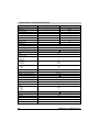
Table of Contents
Chapter 1: General Information ..................................................... 15
1. ACOPOS™ .........................................................................................................................
1.1 Speed and Precision .....................................................................................................
1.2 Maximum Security .........................................................................................................
1.3 Modular, Precise and Communicative ...........................................................................
1.4 Configuring Instead of Programming .............................................................................
1.5 PLCopen Motion Control Function Blocks .....................................................................
1.6 Smart Process Technology ...........................................................................................
1.7 A Unit Made Up of Hardware and Software ..................................................................
1.8 Real-time Movement Analysis .......................................................................................
1.9 ACOPOS™ and CNC Applications ...............................................................................
2. ACOPOS™ Configurations .................................................................................................
2.1 General Information .......................................................................................................
2.2 ACOPOS™ in ETHERNET Powerlink Network ............................................................
2.2.1 Recommended Topology ........................................................................................
2.2.2 Further Literature ....................................................................................................
2.2.3 ACOPOS™ in ETHERNET Powerlink - Star Structure ...........................................
2.2.4 ACOPOS™ in ETHERNET Powerlink - Line Structure ...........................................
2.2.5 ACOPOS™ in ETHERNET Powerlink - Mixed Structure ........................................
2.3 ACOPOS™ on the CAN Bus .........................................................................................
2.3.1 Drive-based Automation with ACOPOS™ ..............................................................
3. Safety Guidelines ................................................................................................................
3.1 General Information .......................................................................................................
3.2 Intended Use .................................................................................................................
3.3 Transport and Storage ..................................................................................................
3.4 Installation .....................................................................................................................
3.5 Operation .......................................................................................................................
3.5.1 Protection Against Coming into Contact with Electrical Parts .................................
3.5.2 Protection from Dangerous Movements .................................................................
3.5.3 Protection from Burns .............................................................................................
3.6 Safety Notices ...............................................................................................................
15
15
15
16
17
18
18
19
20
21
22
22
22
22
23
23
24
25
26
27
28
28
28
29
29
30
30
31
32
32
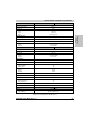
Chapter 2: Technical Data .............................................................. 33
1. ACOPOS Servo Family ......................................................................................................
1.1 Modular Servo Drive Concept .......................................................................................
1.2 General Description .......................................................................................................
1.2.1 24 VDC Supply During Power Failures ...................................................................
1.3 Indications .....................................................................................................................
1.3.1 LED Status ..............................................................................................................
1.4 ACOPOS 1010, 1016 ....................................................................................................
1.4.1 Order Data ..............................................................................................................
1.4.2 Technical Data ........................................................................................................
1.5 ACOPOS 1022, 1045, 1090 ..........................................................................................
1.5.1 Order Data ..............................................................................................................
1.5.2 Technical Data ........................................................................................................
1.6 ACOPOS 1180, 1320 ....................................................................................................
ACOPOS User's Manual V 1.3.1
33
33
34
35
36
37
39
39
40
43
43
44
47
7
Table of Contents
1.6.1 Order Data ..............................................................................................................
1.6.2 Technical Data ........................................................................................................
1.7 ACOPOS 1640, 128M ...................................................................................................
1.7.1 Order Data ..............................................................................................................
1.7.2 Technical Data ........................................................................................................
2. ACOPOS Plug-in Modules ..................................................................................................
2.1 General Information .......................................................................................................
2.2 Overview .......................................................................................................................
2.3 AC110 - CAN Interface ..................................................................................................
2.3.1 General Description ................................................................................................
2.3.2 Order Data ..............................................................................................................
2.3.3 Technical Data ........................................................................................................
2.3.4 CAN Node Number Settings ...................................................................................
2.3.5 Indications ...............................................................................................................
2.3.6 Firmware .................................................................................................................
2.4 AC112 - ETHERNET Powerlink Interface .....................................................................
2.4.1 General Description ................................................................................................
2.4.2 Order Data ..............................................................................................................
2.4.3 Technical Data ........................................................................................................
2.4.4 Powerlink Station Number Settings ........................................................................
2.4.5 Indications ...............................................................................................................
2.4.6 Firmware .................................................................................................................
2.5 AC120 - EnDat Encoder Interface .................................................................................
2.5.1 General Description ................................................................................................
2.5.2 Order Data ..............................................................................................................
2.5.3 Technical Data ........................................................................................................
2.5.4 Indications ...............................................................................................................
2.5.5 Firmware .................................................................................................................
2.6 AC122 - Resolver Interface ...........................................................................................
2.6.1 General Description ................................................................................................
2.6.2 Order Data ..............................................................................................................
2.6.3 Technical Data ........................................................................................................
2.6.4 Indications ...............................................................................................................
2.6.5 Firmware .................................................................................................................
2.7 AC123 - Incremental Encoder and SSI Absolute Encoder Interface .............................
2.7.1 General Description ................................................................................................
2.7.2 Order Data ..............................................................................................................
2.7.3 Technical Data ........................................................................................................
2.7.4 Indications ...............................................................................................................
2.7.5 Firmware .................................................................................................................
2.8 AC130 - Digital Mixed Module .......................................................................................
2.8.1 General Description ................................................................................................
2.8.2 Order Data ..............................................................................................................
2.8.3 Technical Data ........................................................................................................
2.8.4 Indications ...............................................................................................................
2.8.5 Firmware .................................................................................................................
2.9 AC131 - Mixed Module ..................................................................................................
8
47
48
51
51
52
55
55
55
56
56
56
56
57
57
57
58
58
58
58
59
60
61
62
62
63
63
64
64
65
65
65
66
67
67
68
68
68
69
70
70
71
71
71
72
74
74
75
ACOPOS User's Manual V 1.3.1
Table of Contents
2.9.1 General Description ................................................................................................ 75
2.9.2 Order Data .............................................................................................................. 75
2.9.3 Technical Data ........................................................................................................ 76
2.9.4 Indications ............................................................................................................... 78
2.9.5 Firmware ................................................................................................................. 78
2.10 AC140 - CPU Module .................................................................................................. 79
2.10.1 General Description .............................................................................................. 79
2.10.2 Order Data ............................................................................................................ 80
2.10.3 Technical Data ...................................................................................................... 80
2.10.4 Indications ............................................................................................................. 85
2.10.5 CAN Node Number Setting (IF2) .......................................................................... 86
2.10.6 Profibus Station Number Setting (IF3) .................................................................. 86
2.10.7 Ethernet Station Number Setting (IF6) .................................................................. 87
2.10.8 Reset Button ......................................................................................................... 87
2.10.9 Program Memory Slot (Compact Flash) ............................................................... 87
2.10.10 Backup Battery .................................................................................................... 88
2.10.11 Input /Output Register ......................................................................................... 89
3. Cables ................................................................................................................................. 91
3.1 General Information ....................................................................................................... 91
3.1.1 Prefabricated Cables .............................................................................................. 91
3.2 Motor Cables ................................................................................................................. 92
3.2.1 Order Data .............................................................................................................. 92
3.2.2 Technical Data ........................................................................................................ 94
3.3 EnDat Cable .................................................................................................................. 96
3.3.1 Order Data .............................................................................................................. 96
3.3.2 Technical Data ........................................................................................................ 96
3.4 Resolver Cables ............................................................................................................ 98
3.4.1 Order Data .............................................................................................................. 98
3.4.2 Technical Data ........................................................................................................ 98
4. Connectors ....................................................................................................................... 100
4.1 General Information ..................................................................................................... 100
4.2 Motor Connectors ........................................................................................................ 101
4.2.1 Order Data ............................................................................................................ 101
4.2.2 Technical Data for 8PM001.00-1 and 8PM002.00-1 ............................................. 102
4.2.3 Technical Data for 8PM003.00-1 .......................................................................... 103
4.3 Encoder Connectors .................................................................................................... 104
4.3.1 Order Data ............................................................................................................ 104
4.3.2 Technical Data for EnDat connector 8PE001.00-1 ............................................... 105
4.3.3 Technical Data for resolver connector 8PR001.00-1 ............................................ 106
Chapter 3: Installation .................................................................. 107
1. General Information ..........................................................................................................
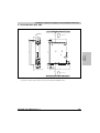
2. Dimension Diagrams and Installation Dimensions ...........................................................
2.1 ACOPOS 1010, 1016 ..................................................................................................
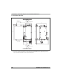
2.2 ACOPOS 1022, 1045, 1090 ........................................................................................
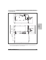
2.3 ACOPOS 1180, 1320 ..................................................................................................
ACOPOS User's Manual V 1.3.1
107
108
108
109
110
9
Table of Contents
2.4 ACOPOS 1640 ............................................................................................................
2.5 ACOPOS 128M ...........................................................................................................
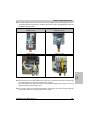
3. Installation and Removal of Plug-in Modules ....................................................................
3.1 General Information .....................................................................................................
3.2 Installation ...................................................................................................................
3.3 Removal ......................................................................................................................
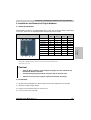
4. Installing Various ACOPOS Series Devices Directly Next to Each Other ........................
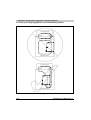
5. Using Cooling Aggregates in Switching Cabinets .............................................................
5.1 General Information .....................................................................................................
5.2 Placing a Cooling Aggregate on Top of the Switching Cabinet ...................................
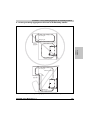
5.3 Placing a Cooling Aggregate on the Front of the Switching Cabinet ...........................
111
112
113
113
113
114
115
117
117
118
119
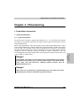
Chapter 4: Dimensioning ............................................................. 121
1. Power Mains Connection ..................................................................................................
1.1 General Information .....................................................................................................
1.1.1 System Configuration ............................................................................................
1.1.2 Supply Voltage Range ..........................................................................................
1.1.3 Protective Ground Connection (PE) ......................................................................
1.2 Dimensioning ...............................................................................................................
1.2.1 Individual ACOPOS Power Mains Connections ....................................................
1.2.2 Implementing ACOPOS Power Mains Connections for Drive Groups ..................
1.3 Fault Current Protection ..............................................................................................
1.3.1 Rated Fault Current ..............................................................................................
1.3.2 Estimating the Discharge Current .........................................................................
1.3.3 Manufacturer Used ...............................................................................................
2. DC Bus .............................................................................................................................
2.1 General Information .....................................................................................................
2.2 Wiring ..........................................................................................................................
2.3 Equal Distribution of the Applied Power via the Power Rectifiers ...............................
2.4 Equal Distribution of the Brake Power on the Braking Resistors ................................
2.5 Connection of External DC Bus Power Supplies .........................................................
3. Motor Connection .............................................................................................................
4. Braking Resistor ...............................................................................................................
4.1 General Information .....................................................................................................
4.2 External Braking Resistor Connection .........................................................................
4.3 Dimensioning the Braking Resistor .............................................................................
4.3.1 Resistance of the External Braking Resistor .........................................................
4.3.2 Power Data for the External Braking Resistor ......................................................
4.3.3 Nominal Voltage of the External Braking Resistor ................................................
4.4 Setting Brake Resistor Parameters .............................................................................
4.4.1 Using the Integrated Braking Resistors ................................................................
4.4.2 Using External Braking Resistors .........................................................................
5. Configuration of ACOPOS Servo Drives ..........................................................................
5.1 Maximum Power Output for All Slots on the ACOPOS Servo Drive ...........................
5.2 24 VDC Current Requirements for the ACOPOS Servo Drive ....................................
6. Formula Variables Used ...................................................................................................
10
121
121
121
122
122
124
124
127
128
128
129
129
130
130
131
132
132
133
134
136
136
137
138
139
140
140
141
141
141
143
143
144
145
ACOPOS User's Manual V 1.3.1
Table of Contents
Chapter 5: Wiring .......................................................................... 147
1. General Information ..........................................................................................................
1.1 Electromagnetic Compatibility of the Installation .........................................................
1.1.1 General Information ..............................................................................................
1.1.2 Installation Notes ..................................................................................................
1.2 Connecting Cables to Plug-in Modules .......................................................................
1.3 Secure Restart Inhibit ..................................................................................................
1.3.1 General Information ..............................................................................................
1.3.2 Principle - Realization of the Safety Function .......................................................
1.3.3 External Wiring ......................................................................................................
1.4 Overview of the Terminal Cross Sections ..................................................................
2. Pin Assignments ACOPOS 1010, 1016 ............................................................................
2.1 Pin Assignments for Plug X1 .......................................................................................
2.2 Pin Assignments for Plug X2 .......................................................................................
2.2.1 8V1010.00-2, 8V1016.00-2 ...................................................................................
2.2.2 8V1010.50-2, 8V1016.50-2 ...................................................................................
2.3 Pin Assignments for Plug X3 .......................................................................................
2.3.1 8V1010.00-2, 8V1016.00-2 ...................................................................................
2.3.2 8V1010.50-2, 8V1016.50-2 ...................................................................................
2.4 Pin Assignments for Plugs X4a, X4b ...........................................................................
2.4.1 Wiring the Output for the Motor Holding Brake .....................................................
2.5 Pin Assignments for Plug X5 .......................................................................................
2.6 Protective Ground Connection (PE) ............................................................................
2.7 Input/Output Circuit Diagram .......................................................................................
3. Pin Assignments ACOPOS 1022, 1045, 1090 .................................................................
3.1 Pin Assignments for Plug X1 .......................................................................................
3.2 Pin Assignments for Plug X2 .......................................................................................
3.3 Pin Assignments for Plug X3 .......................................................................................
3.4 Pin Assignments for Plugs X4a, X4b ...........................................................................
3.4.1 Wiring the Output for the Motor Holding Brake .....................................................
3.5 Pin Assignments for Plug X5 .......................................................................................
3.6 Protective Ground Connection (PE) ............................................................................
3.7 Input/Output Circuit Diagram .......................................................................................
4. Pin Assignments ACOPOS 1180, 1320 ...........................................................................
4.1 Pin Assignments for Plug X1 .......................................................................................
4.2 Pin Assignments for Plug X2 .......................................................................................
4.3 Pin Assignments for Plug X3 .......................................................................................
4.4 Pin Assignments for Plugs X4a, X4b ...........................................................................
4.4.1 Wiring the output for the motor holding brake .......................................................
4.5 Pin Assignments for Plug X5 .......................................................................................
4.6 Pin Assignments for Plug X6 .......................................................................................
4.7 Protective Ground Connection (PE) ............................................................................
4.8 Input/Output Circuit Diagram .......................................................................................
5. Pin Assignments ACOPOS 1640, 128M ..........................................................................
5.1 Pin Assignments for Plug X1 .......................................................................................
5.2 Pin Assignments X2 ....................................................................................................
5.3 Pin Assignments X3 ....................................................................................................
ACOPOS User's Manual V 1.3.1
147
147
147
148
152
153
153
154
155
165
166
167
167
167
168
168
168
169
169
169
171
171
172
174
175
175
176
176
176
178
178
179
181
182
182
183
183
183
185
185
186
187
189
190
190
191
11
Table of Contents
5.4 Pin Assignments for Plugs X4a, X4b ...........................................................................
5.4.1 Wiring the Output for the Motor Holding Brake .....................................................
5.5 Pin Assignments X5 ....................................................................................................
5.6 Pin assignments X6 .....................................................................................................
5.7 Input/Output Circuit Diagram .......................................................................................
6. Pin Assignments Plug-in Modules ....................................................................................
6.1 AC110 - CAN Interface ................................................................................................
6.1.1 Pin Assignments ...................................................................................................
6.1.2 Input/Output Circuit Diagram ................................................................................
6.2 AC112 - ETHERNET Powerlink Interface ...................................................................
6.2.1 Pin Assignments ...................................................................................................
6.2.2 Input/Output Circuit Diagram ................................................................................
6.3 AC120 - EnDat Encoder Interface ...............................................................................
6.3.1 Pin Assignments ...................................................................................................
6.3.2 Input/Output Circuit Diagram ................................................................................
6.4 AC122 - Resolver Interface .........................................................................................
6.4.1 Pin Assignments ...................................................................................................
6.4.2 Input/Output Circuit Diagram ................................................................................
6.5 AC123 - Incremental Encoder and SSI Absolute Encoder Interface ...........................
6.5.1 Pin Assignments ...................................................................................................
6.5.2 Input/Output Circuit Diagram ................................................................................
6.6 AC130 - Digital Mixed Module .....................................................................................
6.6.1 Pin Assignments ...................................................................................................
6.6.2 Input/Output Circuit Diagram ................................................................................
6.7 AC131 - Mixed Module ................................................................................................
6.7.1 Pin Assignments ...................................................................................................
6.7.2 Input/Output Circuit Diagram ................................................................................
6.8 AC140 - CPU Module ..................................................................................................
6.8.1 Application Interface IF1 (RS232) .........................................................................
6.8.2 Application Interface IF2 (CAN) ............................................................................
6.8.3 Application Interface IF3 (Profibus) .......................................................................
6.8.4 X4 Connector (inputs/outputs) ..............................................................................
6.8.5 Application Interface IF6 (Ethernet) .....................................................................
7. Cables ...............................................................................................................................
7.1 Motor Cables ...............................................................................................................
7.1.1 Motor Cable Construction .....................................................................................
7.1.2 Pin Assignments for 8CMxxx.12-1, 8CMxxx.12-3 .................................................
7.1.3 Cable Schematic for 8CMxxx.12-1, 8CMxxx.12-3 ................................................
7.1.4 Pin Assignments for 8CMxxx.12-5 ........................................................................
7.1.5 Cable Schematic for 8CMxxx.12-5 .......................................................................
7.2 EnDat Encoder Cables ................................................................................................
7.2.1 EnDat Encoder Cable Construction ......................................................................
7.2.2 Pin Assignments ...................................................................................................
7.2.3 Cable Schematic ...................................................................................................
7.3 Resolver Cables ..........................................................................................................
7.3.1 Resolver Cable Construction ................................................................................
7.3.2 Pin Assignments ...................................................................................................
12
191
191
193
193
194
196
196
196
196
197
197
198
199
199
200
201
201
202
203
203
204
205
205
206
207
207
208
209
210
210
210
211
211
212
212
212
213
213
214
214
215
215
215
216
217
217
217
ACOPOS User's Manual V 1.3.1
Table of Contents
7.3.3 Cable Schematic ................................................................................................... 218
Chapter 6: Getting Started ........................................................... 219
1. Preparation .......................................................................................................................
1.1 Unpacking the ACOPOS Servo Drive .........................................................................
1.2 Installing and Connecting the ACOPOS Servo Drive ..................................................
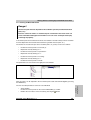
1.3 Connecting the ACOPOS Servo Drive with a B&R PLC .............................................
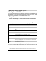
2. Starting Up an ACOPOS Servo Drive ...............................................................................
2.1 General Information .....................................................................................................
2.1.1 Sample project ......................................................................................................
2.1.2 Preparing the Hardware for Sample Project acp10.gdm ......................................
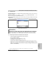
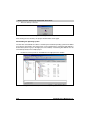
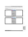
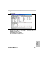
2.2 Commissioning ............................................................................................................
2.2.1 Load Sample Project .............................................................................................
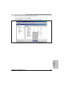
2.2.2 Preset Values for the Sample Project ...................................................................
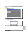
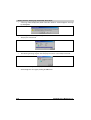
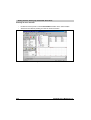
2.2.3 Preset Values Concerning Wiring .........................................................................
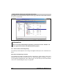
2.2.4 Downloading the Project .......................................................................................
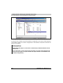
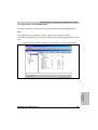
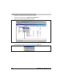
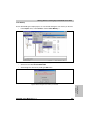
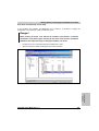
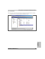
2.2.5 Test Function ........................................................................................................
2.2.6 Starting the Motor Movement ................................................................................
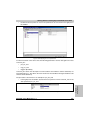
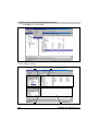
2.3 Network Command Trace ...........................................................................................
219
219
219
219
220
220
221
221
222
222
225
230
236
239
241
248
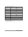
Chapter 7: Standards and Certifications .................................... 249
1. Valid European Guidelines ...............................................................................................
2. Valid Standards ................................................................................................................
3. Environmental Limits ........................................................................................................
3.1 Mechanical Conditions According to IEC 61800-2 ......................................................
3.1.1 Operation ..............................................................................................................
3.1.2 Transport ...............................................................................................................
3.2 Climate Conditions According to IEC 61800-2 ............................................................
3.2.1 Operation ..............................................................................................................
3.2.2 Storage .................................................................................................................
3.2.3 Transport ...............................................................................................................
4. Requirements for Immunity to Disturbances (EMC) .........................................................
4.1 Evaluation Criteria (performance criteria) ....................................................................
4.2 Low Frequency Disturbances According to IEC 61800-3 ............................................
4.2.1 Power Mains Harmonics and Commutation Notches / Voltage Distortions ..........
4.2.2 Voltage Changes, Deviations, Dips and Short-term Interruptions ........................
4.2.3 Asymmetric Voltage und Frequency Changes ......................................................
4.3 High Frequency Disturbances According to IEC 61800-3 ...........................................
4.3.1 Electrostatic Discharge .........................................................................................
4.3.2 Electromagnetic Fields ..........................................................................................
4.3.3 Burst ......................................................................................................................
4.3.4 Surge ....................................................................................................................
4.3.5 High Frequency Conducted Disturbances ............................................................
5. Requirements for Emissions (EMC) .................................................................................
5.1 High Frequency Emissions According to IEC 61800-3 ...............................................
5.1.1 Emissions on the Power Connections ..................................................................
ACOPOS User's Manual V 1.3.1
249
249
250
250
250
250
250
250
250
251
252
252
252
252
252
253
253
253
253
253
254
254
255
255
255
13
Table of Contents
5.1.2 Electromagnetic Emissions ...................................................................................
6. Other Environmental Limit Values According to IEC 61800-2 ..........................................
7. International Certifications ................................................................................................
8. Standards, Definitions for Safety Techniques ...................................................................
14
255
256
257
258
ACOPOS User's Manual V 1.3.1
Chapter 1
General Information
General Information • ACOPOS™
Chapter 1 • General Information
1. ACOPOS™
1.1 Speed and Precision
With the ACOPOS™ servo family, B&R provides the basis for complete and uniform automation
solutions. Branch specific functions and intuitive tools allow for short development times and
create more room for innovation.
A decisive criteria for automation solutions is a fast and precise reaction to events dependent on
the application or immediate changes to the production process. Therefore, ACOPOS™ servo
drives work with very short scan times and communication cycles of 400 µs, which only amount
to 50 µs in the control loop.
1.2 Maximum Security
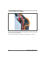
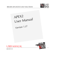
The ACOPOS™ servo family was tested thoroughly during the development phase. Under
difficult conditions, such as heavy vibrations or increased temperatures, the devices were
subject to loads that greatly exceed the values that occur in normal everyday operation.
Figure 1: EMC test on the ACOPOS™ servo drives - maximum security for the user
ACOPOS User's Manual V 1.3.1
15
General Information • ACOPOS™
EMC was given special attention to facilitate use in a rough industrial environment. Field tests
have been carried out under difficult conditions in addition to the tests defined in the standard.
The results confirm the excellent values measured by the testing laboratory and during
operation.
The necessary filters, which meet CE guidelines, are also integrated in the device.
Using computer-aided models, the thermal behavior of the entire system is pre-calculated based
on measured currents and temperatures. This results in maximum performance by taking
advantage of the system's full capabilities.
ACOPOS™ servo drives use the information on the motor's embedded parameter chip, which
contains all relevant mechanical and electronic data. The extensive and error-prone task of
setting parameters manually is no longer necessary and start-up times are substantially
reduced. During service, relevant data can be requested and the cause of problems that may
exist can be determined.
1.3 Modular, Precise and Communicative
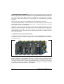
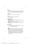
The I/O points needed to operate a servo axis are part of the standard equipment for ACOPOS™
servo drives. The user is provided two trigger inputs for tasks requiring precise measurements
or print mark control.
Figure 2: Plug-in modules allow optimized, application-specific configuration of ACOPOS™ servo drives
Further configuration of the ACOPOS™ servo drive to meet the respective application-specific
demands takes place using plug-in modules. Plug-in modules are available to make network
connections with other drives, controllers and visualization devices as well as for the connection
of encoders, sensors and actuators. Additionally, CPU modules for controller and drive
integration (drive-based automation) are also available.
16
ACOPOS User's Manual V 1.3.1
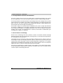
1.4 Configuring Instead of Programming
ACOPOS™ servo drives can be configured for demanding positioning tasks such as electronic
gears or cam profiles. Based on long-term cooperation with customers from all over the world,
B&R shares its know-how in the form of compact function blocks for many applications. Industryspecific functionality can be quickly and easily implemented in an application program.
Figure 3: Configuring ACOPOS™ servo drives using B&R Automation Studio™ guarantees fast and easy
implementation of application requirements
ACOPOS User's Manual V 1.3.1
17
Chapter 1
General Information
General Information • ACOPOS™
General Information • ACOPOS™
1.5 PLCopen Motion Control Function Blocks
The area of motion control is one of the central topics in automation technology. This is partly
due to its high portion of the entire automation expenses and the resulting savings potential.
The PLCopen motion control function blocks (conforming to IEC 61131-3) support the user when
implementing these possibilities by providing vendor-independence and reducing development
times. The user can choose between the programming languages Ladder Diagram (LD),
Structured Text (ST) and the high-level language "C".
The function range of the function blocks is divided into the areas of single and multi-axis
movements. In addition to the usual relative and absolute movements, the first of the two areas
also includes the possibility of overlapping movements. In the area of multi-axis movements,
functions such as gears, cam profile functions, up/down synchronization and differential gear
(changing phase angles) are supported.
1.6 Smart Process Technology
Smart Process Technology meets the customer’s need for cost-effective solutions and high
production speeds. This freely configurable technology library, is homogenously integrated into
the existing Motion Control product.
Using indirect process parameters makes it possible to eliminate sensors, which are often not
fast enough to keep up with high production speeds. Synchronous processing and short
response times make it possible to achieve excellent productivity and precision. For example,
highly efficient and intelligent decentralized units allow seamless quality control. In the field, this
significantly reduces cycle times while improving component quality.
This meets the requirements of modern motion control products such as high product quality,
machine productivity along with short maintenance and down times and, to a greater extent,
seamless quality control during production.
18
ACOPOS User's Manual V 1.3.1
1.7 A Unit Made Up of Hardware and Software
Programming all B&R products takes place in a uniform manner in B&R Automation Studio™
with Windows look and feel. Complex drive solutions can be created after a short orientation
period. Adding hardware components and program sections, as well as their configuration, is
done in dialog boxes; this reduces project development times considerably.
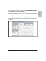
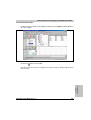
Axis movements can be checked without programming using NC Test. All types of movements,
ranging from point-to-point to gear functions, can be carried out interactively. The reaction of the
axis can be seen online in the monitor window. The trace function records relevant drive data for
clear evaluation.
Figure 4: Optimal control of the movement using NC Test and Trace function
ACOPOS User's Manual V 1.3.1
19
Chapter 1
General Information
General Information • ACOPOS™
General Information • ACOPOS™
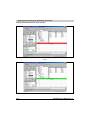
1.8 Real-time Movement Analysis
The drive is monitored in real-time using the oscilloscope function. Many trigger possibilities
generate informative data for analysis of the movement during operation. The graphic display
allows the user to make fine adjustments and optimizations of the movement in the microsecond
range. The integration of powerful tools, such as the cam editor, reduces programming for
complex coupled movements to simple drag-and-drop procedures. The results and effects on
speed, acceleration and jolt can be immediately analyzed graphically.
Figure 5: Cam editor - create movements simply and precisely
20
ACOPOS User's Manual V 1.3.1
1.9 ACOPOS™ and CNC Applications
The integrated "Soft" CNC system from B&R unites all of the software components necessary
for machine automation in a 64-bit processor platform, which means sufficient computing power
even for complex processing machines. The integrated system architecture, together with
ACOPOS™ servo drives, provides many opportunities regarding reaction speed, data
throughput and precision and reduces costs at the same time.
•
Uniformly integrated ACOPOS™ servo drive technology
•
Powerful and fast-reacting
•
Unlimited flexibility of PLC and CNC systems provides room for automation ideas
•
8 independent CNC channels
•
Up to a total of 100 axes for positioning, CNC, electronic gears
•
Individual graphic interface
•
Almost unlimited system memory for programs, diagnostics, and process data
•
Internet or intranet connection for inspection or remote maintenance
Leading manufacturers of water jet, laser and torch cutting production technologies are already
utilizing these technological advantages.
ACOPOS User's Manual V 1.3.1
21
Chapter 1
General Information
General Information • ACOPOS™
General Information • ACOPOS™ Configurations
2. ACOPOS™ Configurations
2.1 General Information
ACOPOS™ servo drives can be used in various configurations depending on the network type
and the requirements of the application.
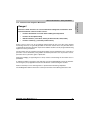
The following ACOPOS™ functions are possible for all configuration examples:
•
Point-to-point
•
Electronic gears
•
Electronic compensation gears
•
Cross cutters
•
Electronic cam profiles
•
Flying saws
•
Line shaft
•
CNC
2.2 ACOPOS™ in ETHERNET Powerlink Network
High-performance machine architectures require flexible networks and field busses. With
ETHERNET Powerlink, a network is available to the user that fully meets the high demands of
dynamic motion systems. ETHERNET Powerlink adapts to the requirements of the machine and
the system. The rigid coupling of many axes with controllers, industrial PCs, I/O systems and
operator panels allows machines and systems to be created with the highest level of precision.
Compatibility to standard Ethernet also reduces the number of networks and fieldbusses on the
machine level.
2.2.1 Recommended Topology
In the Powerlink network (seen from the manager), the tree structure should always come first
followed then by the line structure. Otherwise, the line structure delay affects the entire tree
beneath it.
Information:
It should be noted that the longest path is allowed a maximum of 10 hubs by the
manager.
22
ACOPOS User's Manual V 1.3.1
General Information • ACOPOS™ Configurations
Chapter 1
General Information
2.2.2 Further Literature
Unless otherwise stated, the recommendations in the following documents apply:
•
"Industrial Ethernet Planning and Installation Guide", Draft 2.0,
IAONA (www.iaona-eu.com)
•
"Guide to Understanding and Obtaining High Quality Generic Cabling",
3P Third Party Testing (www.3ptest.dk)
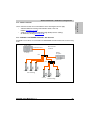
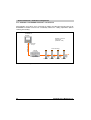
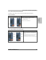
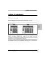
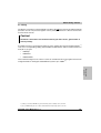
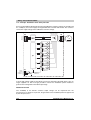
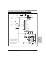
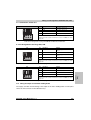
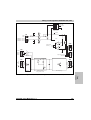
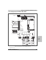
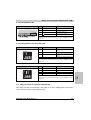
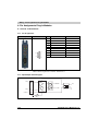
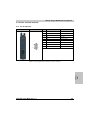
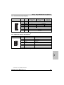
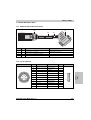
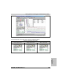
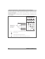
2.2.3 ACOPOS™ in ETHERNET Powerlink - Star Structure
ACOPOS™ servo drives are connected to the ETHERNET Powerlink network in star-form using
hubs.
Control system
Max. 253 nodes
in network
ETHERNET Powerlink
System 2005
0 … Manager
Remote
I/O system
Hub
....
System 2003
Hub
.....
ACOPOS
ACOPOS
ACOPOS
Drive technology
ACOPOS
ACOPOS
ACOPOS
Drive technology
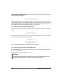
Figure 6: ACOPOS™ in ETHERNET Powerlink star structure
ACOPOS User's Manual V 1.3.1
23
General Information • ACOPOS™ Configurations
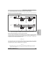
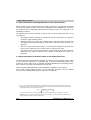
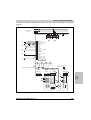
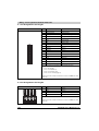
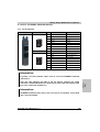
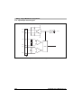
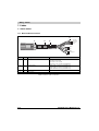
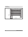
2.2.4 ACOPOS™ in ETHERNET Powerlink - Line Structure
All ACOPOS™ servo drives serve as mini-hub for cabling, and allow line-formed routing of the
ETHERNET Powerlink network. This considerably reduces the cabling expenditure (without
reducing functionality).
Control system,
visualization &
operation
Maximum 10 hubs in
longest path
(ACOPOS = Hub)
ETHERNET Powerlink
Power Panel
0 … Manager
Drive technology
Remote
I/O system
System 2003
ACOPOS
ACOPOS
ACOPOS
ACOPOS
Figure 7: ACOPOS™ in ETHERNET Powerlink line structure
24
ACOPOS User's Manual V 1.3.1
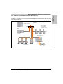
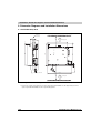
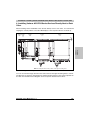
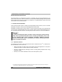
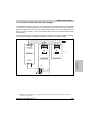
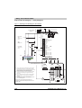
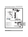
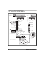
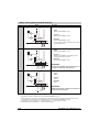
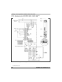
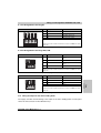
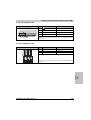
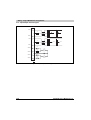
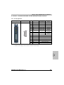
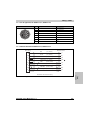
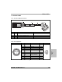
2.2.5 ACOPOS™ in ETHERNET Powerlink - Mixed Structure
ACOPOS™ servo drives are connected to the ETHERNET Powerlink network in both star-form
using hubs and line-form.
Control system
Max. 253 nodes
in network
ETHERNET Powerlink
Max. 10 hubs in
a line structure
(ACOPOS = Hub)
Hub
System 2005
0 … Manager
....
Remote
I/O system
System 2003
ACOPOS
ACOPOS
ACOPOS
Drive technology
ACOPOS
ACOPOS
ACOPOS
Drive technology
ACOPOS
X2X Link
Remote
I/O system
System 2003
X67
X67
Figure 8: ACOPOS™ in mixed ETHERNET Powerlink structure
ACOPOS User's Manual V 1.3.1
25
Chapter 1
General Information
General Information • ACOPOS™ Configurations
General Information • ACOPOS™ Configurations
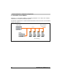
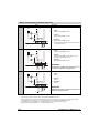
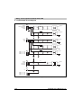
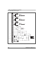
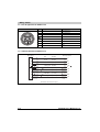
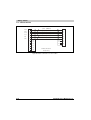
2.3 ACOPOS™ on the CAN Bus
CAN bus is a cost-effective fieldbus for networking ACOPOS™ servo drives with controllers,
industrial PCs, I/O systems and operator panels.
The dynamic requirements for small and mid-sized machines with several axes can be handled
ideally using CAN bus.
Control system
Max. 16 ACOPOS
in CAN network
CAN bus
System 2005
Remote
I/O system
System 2003
ACOPOS
ACOPOS
ACOPOS
ACOPOS
Drive technology
Figure 9: ACOPOS™ on the CAN bus
26
ACOPOS User's Manual V 1.3.1
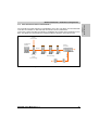
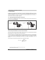
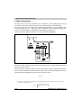
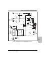
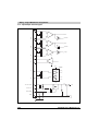
2.3.1 Drive-based Automation with ACOPOS™
The controller is located centrally in an ACOPOS™ servo drive. The drives are networked with
each other via CAN bus so that multi-axis movements can be synchronized.
Control of the simple operation/visualization is handled by the controller in the ACOPOS™ servo
drive. I/O signals are connected in the switching cabinet or directly in the machine room.
Host/line
communication
Visualization &
operation
Remote
I/O system
CAN bus
System 2003
ACOPOS
with AC14x
ACOPOS
ACOPOS
ACOPOS
X2X Link
Panelware
Drive technology
Control,
drive technology
X67
X67
Figure 10: Drive-based automation with ACOPOS™
ACOPOS User's Manual V 1.3.1
27
Chapter 1
General Information
General Information • ACOPOS™ Configurations
General Information • Safety Guidelines
3. Safety Guidelines
3.1 General Information
B&R servo drives and servo motors have been designed, developed and manufactured for
conventional use in industry. They were not designed, developed and manufactured for any use
involving serious risks or hazards that without the implementation of exceptionally stringent
safety precautions could lead to death, injury, serious physical damage or loss of any other kind.
Such risks include in particular the use of these devices to monitor nuclear reactions in nuclear
power plants, as well as flight control systems, flight safety, the control of mass transportation
systems, medical life support systems, and the control of weapons systems.
Danger!
Servo drives and servo motors can have bare parts with voltages applied (e.g.
terminals) or hot surfaces. Additional sources of danger result from moving
machine parts. Improperly removing the required covers, inappropriate use,
incorrect installation or incorrect operation can result in severe personal injury or
damage to property.
All tasks, such as transport, installation, commissioning and service, are only allowed to be
carried out by qualified personnel. Qualified personnel are persons familiar with transport,
mounting, installation, commissioning and operation of the product and have the respective
qualifications (e.g. IEC 60364). National accident prevention guidelines must be followed.
The safety guidelines, connection descriptions (type plate and documentation) and limit values
listed in the technical data are to be read carefully before installation and commissioning and
must be observed.
Danger!
Handling servo drives and servo motors incorrectly can cause severe personal
injury or damage to property!
3.2 Intended Use
Servo drives are components designed to be installed in electrical systems or machines. They
are not being used as intended unless the machine meets EG regulation 98/37/EG (machine
regulation) as well as regulation 89/336/EWG (EMC regulation).
Servo drives are only allowed to be operated directly on grounded, three-phase industrial mains
(TN, TT power mains). When using them in living areas, shops and small businesses, additional
filtering measures must be implemented by the user.
28
ACOPOS User's Manual V 1.3.1
Danger!
Servo drives are not allowed to be operated directly on IT and TN-S mains with a
grounded phase conductor and protective ground conductor!
The technical data as well as the values for connection and environmental specifications can be
found on the type plate and in the user's manual. The connection and environmental
specifications must be met!
Danger!
Electronic devices are generally not fail-safe. If the servo drive fails, the user is
responsible for making sure that the motor is placed in a secure state.
3.3 Transport and Storage
During transport and storage, devices must be protected from excessive stress (mechanical
load, temperature, humidity, aggressive atmosphere).
Servo drives contain components sensitive to electrostatic charges which can be damaged by
inappropriate handling. It is therefore necessary to provide the required safety precautions
against electrostatic discharges during installation or removal of servo drives.
3.4 Installation
The installation must take place according to the user's manual using suitable equipment and
tools.
The devices are only allowed to be installed without voltage applied and by qualified personnel.
Before installation, voltage to the switching cabinet should be switched off and prevented from
being switched on again.
The general safety regulations and national accident prevention guidelines (e.g. VBG 4) must be
observed when working with high voltage systems.
The electrical installation must be carried out according to the relevant guidelines (e.g. line cross
section, fuse, protective ground connection, also see chapter 4 "Dimensioning").
ACOPOS User's Manual V 1.3.1
29
Chapter 1
General Information
General Information • Safety Guidelines
General Information • Safety Guidelines
3.5 Operation
3.5.1 Protection Against Coming into Contact with Electrical Parts
Danger!
To operate servo drives, it is necessary that certain parts are carrying voltages over
42 VDC. A life-threatening electrical shock could occur if you touch these parts. This
could result in death, severe injury or material damage.
Before turning on a servo drive, make sure that the housing is properly connected to ground (PE
rail). The ground connection must be made, even when testing the servo drive or when operating
it for a short time!
Before turning the device on, make sure that all voltage carrying parts are securely covered.
During operation, all covers and switching cabinet doors must remain closed.
Control and high power contacts can have voltage applied, even when the motor is not turning.
Touching the contacts when the device is switched on is not permitted.
Before working on servo drives, they must be disconnected from the power mains and prevented
from being switched on again.
Danger!
After switching off the servo drive, wait until the DC bus discharge time of at least
five minutes has passed. The voltage currently on the DC bus must be measured
between -DC1 and +DC1 with a suitable measuring device before beginning work.
This voltage must be less than 42 V DC to rule out danger. The Run LED going out
does not indicate that voltage is not present on the device!
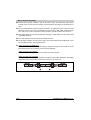
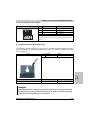
The servo drives are labeled with the following warning signs:
Figure 11: Warning signs on the servo drives
The connections for the signal voltages (5 to 30 V) found on the servo drives are isolated circuits.
Therefore, the signal voltage connections and interfaces are only allowed to be connected to
devices or electrical components with sufficient isolation according to IEC 60364-4-41 or
EN 50178.
Never remove the electrical connections from the servo drive with voltage applied. In unfavorable
conditions, arcs can occur causing personal injury and damage to contacts.
30
ACOPOS User's Manual V 1.3.1
3.5.2 Protection from Dangerous Movements
Danger!
Incorrect control of motors can cause unwanted and dangerous movements! Such
incorrect behavior can have various causes:
•
Incorrect installation or an error when handling the components
•
Incorrect or incomplete wiring
•
Defective devices (servo drive, motor, position encoder, cable, brake)
•
Incorrect control (e.g. caused by software error)
Some of these causes can be recognized and prevented by the servo drive using internal
monitoring. However, it is generally possible for the motor shaft to move every time the device
is switched on! Therefore protection of personnel and the machine can only be guaranteed using
higher level safety precautions.
The movement area of machines must be protected to prevent accidental access. This type of
protection can be obtained by using stabile mechanical protection such as protective covers,
protective fences, protective gates or photocells.
Removing, bridging or bypassing these safety features and entering the movement area is
prohibited.
A sufficient number of emergency stop switches are to be installed directly next to the machine.
The emergency stop equipment must be checked before commissioning the machine.
Remove shaft keys on free running motors or prevent them from being catapulted.
The holding brake built into the motors cannot prevent hoists from allowing the load to sink.
ACOPOS User's Manual V 1.3.1
31
Chapter 1
General Information
General Information • Safety Guidelines
General Information • Safety Guidelines
3.5.3 Protection from Burns
The surfaces of servo drives and servo motors can become very hot during operation.
Therefore, the servo drives are labeled with the following warning:
Figure 12: "Hot surface" warning
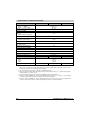
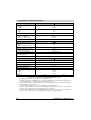
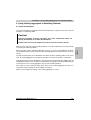
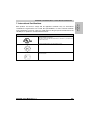
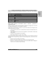
3.6 Safety Notices
The safety notices in this manual are organized as follows:
Safety notices
Description
Danger!
Disregarding the safety regulations and guidelines can be life-threatening.
Warning!
Disregarding the safety regulations and guidelines can result in severe injury or major damage to material.
Caution!
Disregarding the safety regulations and guidelines can result in injury or damage to material.
Information:
Important information for preventing errors
Table 1: Description of the safety notices used in this manual
32
ACOPOS User's Manual V 1.3.1
Technical Data • ACOPOS Servo Family
Chapter 2 • Technical Data
1.1 Modular Servo Drive Concept
Controlling your power transmission system with B&R ACOPOS servo drives allows you to fully
use the advantages of an optimized system architecture. In this way, applications that require
additional positioning tasks such as torque limitation or torque control can be created quickly and
elegantly.
The flexible system concept for B&R servo drives is achieved using matched hardware and
software components. You can select the optimal system configuration for your application and
increase your competitiveness.
•
Perfect integration in the B&R 2000 product family
•
Object-oriented axis programming minimizes development time and increases reusability
•
Integrated technology functions for branch specific tasks
•
Operation of synchronous and asynchronous motors possible
•
Current controller scan time up to 50 µs
•
Reduced commissioning and service times using "embedded motor parameter chip"
•
CAN and Powerlink network connection
•
Input voltage range from 400 - 480 VAC (±10 %) for use worldwide
•
Connection possibilities for all standard encoder systems
•
Up to two free slots for optional technology modules
•
Electronic secure restart inhibit integrated
ACOPOS User's Manual V 1.3.1
33
Chapter 2
Technical Data
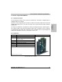
1. ACOPOS Servo Family
Technical Data • ACOPOS Servo Family
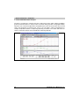
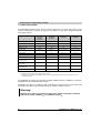
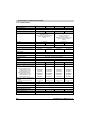
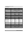
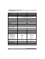
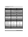
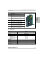
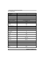
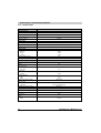
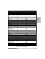
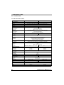
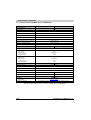
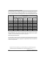
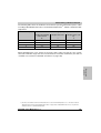
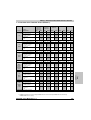
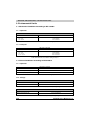
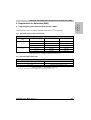
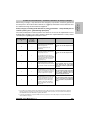
1.2 General Description
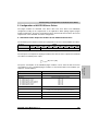
The ACOPOS servo drive series covers a current range from 1.0 - 128 A and a power range
from 0.5 - 64 kW with 11 devices in 4 groups. The devices in a group are designed using the
same basic concept.
Group
8V1010.00-2
8V1010.50-2
8V1016.00-2
8V1016.50-2
8V1022.00-2
8V1045.00-2
8V1090.00-2
8V1180.00-2
8V1320.00-2
8V1640.00-2
8V128M.00-2
Power Connections
Plug connection
Plug connection
Plug connection
Fixed
Integrated Line Filter
Yes
Yes
Yes
Yes
Mains Failure Monitoring
Yes
Yes
Yes
Yes
DC Bus Connection
24 VDC Supply
Yes
Yes
Yes
Yes
External 1)
External 1)
External or internal via
DC bus
External or internal via
DC bus
24 VDC Output
No
No
24 V / 0.5 A
24 V / 0.5 A
Integrated Brake Chopper
Yes
Yes
Yes
Yes
Internal Braking Resistor
Yes
Yes
Yes
Yes 2)
Connection of External Braking
Resistor Possible
No
No
Yes
Yes
Monitored Output for Motor
Holding Brake
Yes
Yes
Yes
Yes
Monitored Input for Motor
Temperature Sensor
Yes
Yes
Yes
Yes
3
4
4
4
Max. Number of Plug-in Modules
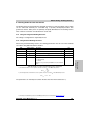
Table 2: General description of the ACOPOS servo drive series
1) External DC bus power supply 0PS320.1 (24V / 20A) can be used.
2) The braking resistor integrated in the ACOPOS servo drives 1640 and 128M is dimensioned so that it is possible to brake to a stop (in
a typical drive situation).
The ACOPOS servo drives also provide a modular fieldbus interface in addition to connection
possibilities for all standard encoder systems.
ACOPOS servo drives are suitable for both synchronous and asynchronous servo motors and
have built-in line filters to meet the limit values for CISPR11, Group 2, Class A.
Warning!
ACOPOS servo drives are suitable for power mains which can provide a maximum
short circuit current of 10000 Aeff at a maximum of 528 Veff.
34
ACOPOS User's Manual V 1.3.1
Technical Data • ACOPOS Servo Family
1.2.1 24 VDC Supply During Power Failures
In order to be able to provide the stop function for category 1 according to IEC 60204-1 during a
power failure, the 24 VDC supply voltage for the servo drives as well as encoders, sensors and
the safety circuit must remain active during the entire stopping procedure.
Danger!
In some applications, the DC bus is not ready for operation or there is not enough
brake energy provided to guarantee that the 24 VDC supply voltage remains active
until the system is stopped.
Internal DC bus power supplies are not ready for operation during the
ACOPOS servo drive switch-on interval, external DC bus power supplies are not
ready for operation while booting.
An external DC bus power supply must be used for ACOPOS servo drives 8V1010 to 8V1090.
A DC bus power supply is integrated in ACOPOS servo drives 8V1180 to 8V128M.
The ACOPOS servo drives with an integrated DC bus power supply provide the 24 VDC supply
for the servo drive and also a 24 VDC output to supply encoders, sensors and the safety circuit.
In may cases, it is not necessary to use an uninterruptible power supply (UPS) which is otherwise
needed.
ACOPOS User's Manual V 1.3.1
35
Chapter 2
Technical Data
The ACOPOS servo drives recognize a power failure and can immediately initiate active braking
of the motor. The brake energy that occurs when braking is returned to the DC bus and the DC
bus power supply can use it to create the 24 VDC supply voltage.
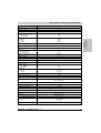
Technical Data • ACOPOS Servo Family
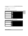
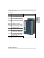
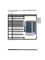
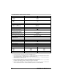
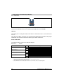
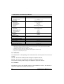
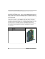
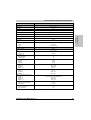
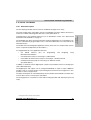
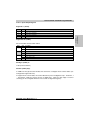
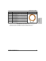
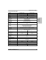
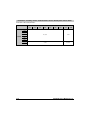
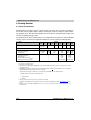
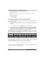
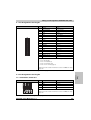
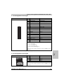
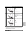
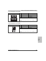
1.3 Indications
The ACOPOS servo drives are equipped with three LEDs for direct diagnosis:
Image
LED
Description
Color
n
Ready
Green
o
Run
Orange
p
Error
Red
Table 3: Status LEDs on ACOPOS servo drives
If no LEDs are lit, the ACOPOS servo drive is not being supplied with 24 VDC.
Danger!
After switching off the device, wait until the DC bus discharge time of at least five
minutes has passed. The voltage currently on the DC bus must be measured with a
suitable measuring device before beginning work. This voltage must be less than
42 VDC to rule out danger. The Run LED going out does not indicate that voltage is
not present on the device!
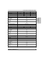
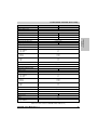
Signal
LED
Ready
Green
Description
Lit when the ACOPOS servo drive is ready for operation and the power level can be enabled (operating
system present and booted, no permanent or temporary errors).
Run
Orange
Lit as soon as the power level is enabled for the ACOPOS servo drive.
Error
Red
Lit when a permanent or temporary error exists on the ACOPOS servo drive. After correcting the error,
the LED is automatically switched off.
Examples of permanent errors:
• Motor feedback not connected or defective
• Low level on the enable input
• Motor temperature sensor not connected or defective
• Internal error on the device (e.g. IGBT heat sink temperature sensor defective)
Examples of temporary errors:
• 24 VDC supply voltage exceeds the tolerance range
• DC bus voltage exceeds the tolerance range
• Internal 15 VDC control voltage exceeds the tolerance range
• IGBT current limit reached
• Over-temperature on the motor (temperature sensor)
• Over-temperature on the servo drive (IGBT junction, heat sink)
• Over-temperature on braking resistor
• CAN or Powerlink network faulty
Table 4: LED status
36
ACOPOS User's Manual V 1.3.1
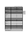
Technical Data • ACOPOS Servo Family
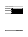
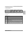
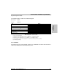
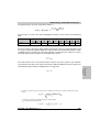
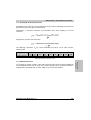
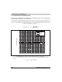
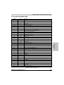
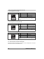
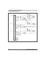
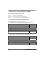
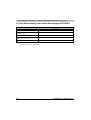
1.3.1 LED Status
The following timing is used for the indication diagrams:
Block size:
125 ms
Repeats after:
3000 ms
Status
1.
LED
Boot procedure for basic hardware active
Chapter 2
Technical Data
Status changes when booting the operating system loader
Display
Green
Orange
Red
2.
Configuration of network plug-in module active
Green
Orange
Red
3.
Waiting for network telegram
Green
Orange
Red
4.
Network communication active
Green
Orange
Red
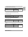
Table 5: Status changes when booting the operating system loader
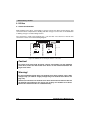
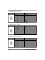
Error status with reference to the CAN plug-in module AC110
Status
LED
Boot error on CAN basic hardware
Display
Green
Orange
Red
Bus Off
Green
Orange
Red
CAN node number is 0
Green
Orange
Red
Table 6: Error status with reference to the CAN plug-in module AC110
ACOPOS User's Manual V 1.3.1
37
Technical Data • ACOPOS Servo Family
Error status with reference to the ETHERNET Powerlink plug-in module AC112
Status
LED
Boot error on Powerlink basic hardware
Display
Green
Orange
Red
Error when booting the AC112-ARM
Green
Orange
Red
Powerlink node number is 0
Green
Orange
Red
Table 7: Error status with reference to the ETHERNET Powerlink plug-in module AC112
38
ACOPOS User's Manual V 1.3.1
Technical Data • ACOPOS Servo Family
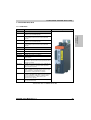
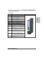
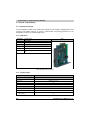
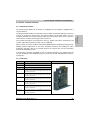
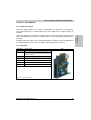
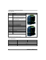
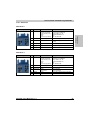
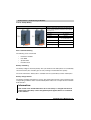
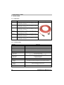
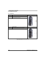
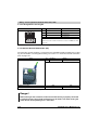
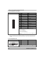
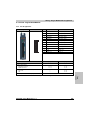
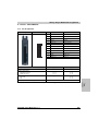
1.4 ACOPOS 1010, 1016
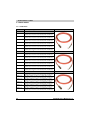
1.4.1 Order Data
Model Number
Short Description
Image
8V1010.00-2
Servo drive 3x400-480V 1.0A 0.45kW, line filter, braking resistor and
electronic secure restart inhibit integrated
8V1010.50-2
Servo drive 3x110-230V / 1x110-230V 2.0A 0.45kW,
line filter, braking resistor and electronic secure restart inhibit
integrated
8V1016.00-2
Servo drive 3x400-480V 1.6A 0.7kW, line filter, braking resistor and
electronic secure restart inhibit integrated
8V1016.50-2
Servo drive 3x110-230V / 1x110-230V 3.2A 0.7kW,
line filter, braking resistor and electronic secure restart inhibit
integrated
8AC110.60-2
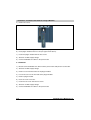
ACOPOS plug-in module, CAN interface
8AC112.60-1
ACOPOS plug-in module, ETHERNET Powerlink interface
8AC120.60-1
ACOPOS plug-in module, EnDat encoder interface
Chapter 2
Technical Data
Servo Drives
Accessories
8AC122.60-2
ACOPOS plug-in module, resolver interface
8AC123.60-1
ACOPOS plug-in module, incremental encoder and SSI absolute
encoder interface
8AC130.60-1
ACOPOS plug-in module, 8 digital I/O configurable in pairs as
24V input or as output 400/100mA, 2 digital outputs 2A, Order TB712
terminal block separately
8AC131.60-1
ACOPOS plug-in module, 2 analog inputs ±10V, 2 digital I/O points
which can be configured as a 24V input or 45mA output, Order
TB712 terminal block separately
8AC140.60-1
ACOPOS plug-in module, CPU, x86 100 MHz Intel compatible, 8 MB
DRAM, 32 kB SRAM, exchangeable application memory: Compact
Flash, 1 CAN interface, 1 Profibus-DP Slave interface,
1 RS232 interface, order program memory separately!
8AC140.61-2
ACOPOS plug-in module, CPU, ARNC0, x86 100 MHz Intel
compatible, 16 MB DRAM, 32 kB SRAM, exchangeable application
memory: Compact Flash, 1 CAN interface, 1 Ethernet interface,
1 Profibus-DP slave interface, 1 RS232 interface, order
application memory separately!
0PS320.1
24 VDC power supply, 3-phase, 20 A, input 400..500 VAC (3 phases),
wide range, DIN rail mounting
Table 8: Order data for ACOPOS 1010, 1016
ACOPOS User's Manual V 1.3.1
39
Technical Data • ACOPOS Servo Family
1.4.2 Technical Data
Product ID
8V1010.00-2
8V1016.00-2
8V1010.50-2
8V1016.50-2
General Information
C-UL-US Listed
In preparation
Power Mains Connection
Mains Input Voltage
3 x 400 VAC to 480 VAC ±10 %
Power filter according
to IEC 61800-3-A11 second environment
(Limits from CISPR11, Group 2,
Class A)
3 x 110 VAC to 230 VAC ±10 %
or
1 x 110 VAC to 230 VAC ±10 %
Power filter according
to IEC 61800-3-A11 second environment
(Limits from CISPR11, Group 2,
Class A)
50 / 60 Hz ± 4%
50 / 60 Hz ± 4%
Frequency
Installed Load
Max. 1.35 kVA
Starting Current
Max. 2.1 kVA
Max. 1.35 kVA
2 A (at 400 VAC)
Max. 2.1 kVA
5 A (at 230 VAC)
Switch-on Interval
> 10 s
Power Loss at Max. Device Power without
Braking Resistor
In preparation
In preparation
In preparation
In preparation
24 VDC Supply
Input Voltage1)
24 VDC +25 % / -20 %
Input Capacitance
5600 µF
Current Requirements 2)
Max. 1.47 A + current for motor holding brake
DC Bus
DC Bus Capacitance
165 µF
2040 µF
Motor Connector
Continuous Current 3)
Reduction of Continuous Current Depending
on Environmental Temperature 4)
Mains Input Voltage: 400 VAC
Switching Frequency 20 kHz
Switching Frequency 10 kHz
Switching Frequency 5 kHz
Mains Input Voltage: 480 VAC
Switching Frequency 20 kHz
Switching Frequency 10 kHz
Switching Frequency 5 kHz
Reduction of Continuous Current Depending
on Altitude
Starting at 500 m Above Sea Level
Peak Current
Nominal Switching Frequency
Maximum Motor Line Length
Protective Measures
1A
1.6 A
2A
3.2 A
In preparation
In preparation
In preparation
In preparation
In preparation
In preparation
In preparation
In preparation
In preparation
In preparation
In preparation
In preparation
In preparation
In preparation
In preparation
In preparation
In preparation
In preparation
In preparation
In preparation
In preparation
In preparation
In preparation
In preparation
0.1 Aeff per 1000 m
0.16 Aeff per 1000 m
0.2 Aeff per 1000 m
0.32 Aeff per 1000 m
2.8 Aeff
5 Aeff
7.8 Aeff
12 Aeff
20 kHz
25 m
Short circuit and ground fault protection
Motor Holding Brake Connection
Maximum Output Current
Protective Measures
1.3 A
Short circuit and ground fault protection
Table 9: Technical data for ACOPOS 1010, 1016
40
ACOPOS User's Manual V 1.3.1
Technical Data • ACOPOS Servo Family
Product ID
8V1010.00-2
8V1016.00-2
8V1010.50-2
8V1016.50-2
Braking Resistor
Peak Power Output
2 kW
Continuous Power Output
In preparation
Trigger Inputs
2
Wiring
Sink
Electrical Isolation
Input - ACOPOS
Input - Input
Yes
No
Input Voltage
Nominal
Maximum
Chapter 2
Technical Data
Number of Inputs
24 VDC
30 VDC
Switching Threshold
LOW
HIGH
<5 V
>15 V
Input Current at Nominal Voltage
Approx. 10 mA
Switching Delay
Max. 55 µs (digitally filtered)
Modulation Compared to Ground Potential
Max. ±38 V
Limit Switch and Reference Inputs
Number of Inputs
3
Wiring
Sink
Electrical Isolation
Input - ACOPOS
Input - Input
Yes
No
Input Voltage
Nominal
Maximum
24 VDC
30 VDC
Switching Threshold
LOW
HIGH
<5 V
>15 V
Input Current at Nominal Voltage
Approx. 4 mA
Switching Delay
Max. 2.0 ms
Modulation Compared to Ground Potential
Max. ±38 V
Enable Input
Number of Inputs
1
Wiring
Sink
Electrical Isolation
Input - ACOPOS
Yes
Input Voltage
Nominal
Maximum
24 VDC
30 VDC
Switching Threshold
LOW
HIGH
<5 V
>15 V
Input Current at Nominal Voltage
Approx. 30 mA
Table 9: Technical data for ACOPOS 1010, 1016 (Forts.)
ACOPOS User's Manual V 1.3.1
41
Technical Data • ACOPOS Servo Family
Product ID
8V1010.00-2
8V1016.00-2
8V1010.50-2
Switching Delay
Enable 1 -> 0, PWM Off
Enable 0 -> 1, Ready for PWM
Max. 2.0 ms
Max. 100 µs
Modulation Compared to Ground Potential
Max. ±38 V
8V1016.50-2
Operational Conditions
Environmental Temperature During
Operation
Max. Environmental Temperature 5)
0 to 50° C
+55 °C
Relative Humidity During Operation
5 to 95%, non-condensing
0 to 500 m
2000 m
Installation at Altitudes Above Sea Level
Maximum Installation Altitude 6)
Degree of Pollution According to IEC 60664-1
2 (non-conductive material)
Over-voltage Category According to
IEC 60364-4-443:1999
II
Protection According to IEC 60529
IP20
Storage and Transport Conditions
Storage Temperature
-25 to +55 °C
Relative Humidity During Storage
5 to 95%, non-condensing
Transport Temperature
-25 to +70° C
Relative Humidity During Transport
95 % at +40 °C
Mechanical Characteristics
Dimensions
Width
Height
Depth
Weight
58.5 mm
257 mm
220 mm
2.5 kg
2.5 kg
2.5 kg
2.5 kg
Table 9: Technical data for ACOPOS 1010, 1016 (Forts.)
1) When using motor holding brakes, the valid input voltage range is reduced. The input voltage range should be selected so that the
proper supply voltage for the motor holding brake can be maintained.
2) The current requirements depend on the configuration of the ACOPOS servo drive.
3) Valid in the following conditions: Mains input voltage 400 VAC, nominal switching frequency, 40 °C environmental temperature,
installation altitudes < 500 m above sea level.
4) The nominal switching frequency values for the respective ACOPOS servo drive are marked in bold.
5) Continuous operation of ACOPOS servo drives at environmental temperatures ranging from 40 °C to max. 55 °C is possible (taking
the continuous current reductions listed into consideration), but results in a shorter lifespan.
6) Continuous operation of ACOPOS servo drives at altitudes ranging from 500 m to 2000 m above sea level is possible (taking the
continuous current reductions listed into consideration). Additional requirements are to be arranged with B&R.
42
ACOPOS User's Manual V 1.3.1
Technical Data • ACOPOS Servo Family
1.5 ACOPOS 1022, 1045, 1090
1.5.1 Order Data
Model Number
Short Description
Image
8V1022.00-2
Servo drive 3 x 400-480V 2.2A 1kW, line filter, braking resistor and
electronic secure restart inhibit integrated
8V1045.00-2
Servo drive 3 x 400-480V 4.4A 2kW, line filter, braking resistor and
electronic secure restart inhibit integrated
8V1090.00-2
Servo drive 3 x 400-480V 8.8A 4kW, line filter, braking resistor and
electronic secure restart inhibit integrated
Chapter 2
Technical Data
Servo Drives
Accessories
8AC110.60-2
ACOPOS plug-in module, CAN interface
8AC112.60-1
ACOPOS plug-in module, ETHERNET Powerlink interface
8AC120.60-1
ACOPOS plug-in module, EnDat encoder interface
8AC122.60-2
ACOPOS plug-in module, resolver interface
8AC123.60-1
ACOPOS plug-in module, incremental encoder and SSI absolute
encoder interface
8AC130.60-1
ACOPOS plug-in module, 8 digital I/O configurable in pairs as
24V input or as output 400/100mA, 2 digital outputs 2A, Order TB712
terminal block separately
8AC131.60-1
ACOPOS plug-in module, 2 analog inputs ±10V, 2 digital I/O points
which can be configured as a 24V input or 45mA output, Order
TB712 terminal block separately
8AC140.60-1
ACOPOS plug-in module, CPU, x86 100 MHz Intel compatible, 8 MB
DRAM, 32 kB SRAM, exchangeable application memory: Compact
Flash, 1 CAN interface, 1 Profibus-DP Slave interface,
1 RS232 interface, order program memory separately!
8AC140.61-2
ACOPOS plug-in module, CPU, ARNC0, x86 100 MHz Intel
compatible, 16 MB DRAM, 32 kB SRAM, exchangeable application
memory: Compact Flash, 1 CAN interface, 1 Profibus-DP slave
interface, 1 RS232 interface, order application memory separately!
0PS320.1
24 VDC power supply, 3-phase, 20 A, input 400..500 VAC (3 phases),
wide range, DIN rail mounting
Table 10: Order data for ACOPOS 1022, 1045, 1090
ACOPOS User's Manual V 1.3.1
43
Technical Data • ACOPOS Servo Family
1.5.2 Technical Data
Product ID
8V1022.00-2
8V1045.00-2
8V1090.00-2
General Information
C-UL-US Listed
Yes
Power Mains Connection
Mains Input Voltage
3 x 400 VAC to 480 VAC ±10 %
Power filter according to IEC 61800-3-A11 second environment
(Limits from CISPR11, Group 2, Class A)
Frequency
50 / 60 Hz ± 4%
Installed Load
Starting Current at 400 VAC
Max. 3 kVA
Max. 5 kVA
Max. 10 kVA
4A
7A
7A
Switch-on Interval
> 10 s
Power Loss at Max. Device Power without
Braking Resistor
Approx. 120 W
Approx. 180 W
Approx. 200 W
24 VDC Supply
Input Voltage 1)
24 VDC +25 % / -25 %
Input Capacitance
8200 µF
Current Requirements 2)
Max. 2.5 A + current for motor holding brake
DC Bus
DC Bus Capacitance
235 µF
470 µF
Motor Connector
Continuous Current 3)
Reduction of Continuous Current Depending
on Environmental Temperature 4)
Mains Input Voltage: 400 VAC
Switching Frequency 20 kHz
Switching Frequency 10 kHz
Switching Frequency 5 kHz
Mains Input Voltage: 480 VAC
Switching Frequency 20 kHz
Switching Frequency 10 kHz
Switching Frequency 5 kHz
Reduction of Continuous Current Depending
on Altitude
Starting at 500 m Above Sea Level
Peak Current
Nominal Switching Frequency
2.2 Aeff
4.4 Aeff
8.8 Aeff
No reduction
No reduction
No reduction
0.13 Aeff per °C (≥ 45 °C)
No reduction
No reduction
0.18 Aeff per °C (≥ 30 °C)
0.18 Aeff per °C (≥ 54 °C)
No reduction
0.13 Aeff per °C (≥ 51 °C)
No reduction
No reduction
0.13 Aeff per °C (≥ 35 °C)
No reduction
No reduction
0.18 Aeff per °C (≥ 18 °C)
0.18 Aeff per °C (≥ 48 °C)
No reduction
0.22 Aeff per 1000 m
0.44 Aeff per 1000 m
0.88 Aeff per 1000 m
14 Aeff
24 Aeff
20 kHz
Maximum Motor Line Length
24 Aeff
10 kHz
25 m
Protective Measures
Short circuit and ground fault protection
Motor Holding Brake Connection
Maximum Output Current
Protective Measures
1A
Short circuit and ground fault protection
Table 11: Technical data for ACOPOS 1022, 1045, 1090
44
ACOPOS User's Manual V 1.3.1
Technical Data • ACOPOS Servo Family
Product ID
8V1022.00-2
8V1045.00-2
8V1090.00-2
Braking Resistor
Peak Power Output
3.5 kW
7 kW
7 kW
Continuous Power Output
130 W
200 W
200 W
Trigger Inputs
2
Wiring
Sink
Electrical Isolation
Input - ACOPOS
Input - Input
Yes
No
Input Voltage
Nominal
Maximum
Chapter 2
Technical Data
Number of Inputs
24 VDC
30 VDC
Switching Threshold
LOW
HIGH
<5V
>15 V
Input Current at Nominal Voltage
Switching Delay
Approx. 10 mA
Max. 55 µs (digitally filtered)
Modulation Compared to Ground Potential
Max. ±38 V
Limit Switch and Reference Inputs
Number of Inputs
3
Wiring
Sink
Electrical Isolation
Input - ACOPOS
Input - Input
Yes
No
Input Voltage
Nominal
Maximum
24 VDC
30 VDC
Switching Threshold
LOW
HIGH
<5V
>15 V
Input Current at Nominal Voltage
Approx. 4 mA
Switching Delay
Max. 2.0 ms
Modulation Compared to Ground Potential
Max. ±38 V
Enable Input
Number of Inputs
1
Wiring
Sink
Electrical Isolation
Input - ACOPOS
Yes
Input Voltage
Nominal
Maximum
24 VDC
30 VDC
Switching Threshold
LOW
HIGH
<5V
>15 V
Input Current at Nominal Voltage
Approx. 30 mA
Table 11: Technical data for ACOPOS 1022, 1045, 1090 (Forts.)
ACOPOS User's Manual V 1.3.1
45
Technical Data • ACOPOS Servo Family
Product ID
8V1022.00-2
8V1045.00-2
Switching Delay
Enable 1 -> 0, PWM Off
Enable 0 -> 1, Ready for PWM
Max. 2.0 ms
Max. 100 µs
Modulation Compared to Ground Potential
Max. ±38 V
8V1090.00-2
Operational Conditions
Environmental Temperature During
Operation
Max. Environmental Temperature 5)
0 to 50° C
+55 °C
Relative Humidity During Operation
5 to 95%, non-condensing
0 to 500 m
2000 m
Installation at Altitudes Above Sea Level
Maximum Installation Altitude 6)
Degree of Pollution According to IEC 60664-1
2 (non-conductive material)
Over-voltage Category According to
IEC 60364-4-443:1999
II
Protection According to IEC 60529
IP20
Storage and Transport Conditions
Storage Temperature
-25 to +55 °C
Relative Humidity During Storage
5 to 95%, non-condensing
Transport Temperature
-25 to +70° C
Relative Humidity During Transport
95 % at +40 °C
Mechanical Characteristics
Dimensions
Width
Height
Depth
Weight
70.5 mm
375 mm
235.5 mm
4.0 kg
4.1 kg
4.4 kg
Table 11: Technical data for ACOPOS 1022, 1045, 1090 (Forts.)
1) When using motor holding brakes, the valid input voltage range is reduced. The input voltage range should be selected so that the
proper supply voltage for the motor holding brake can be maintained.
2) The current requirements depend on the configuration of the ACOPOS servo drive.
3) Valid in the following conditions: Mains input voltage 400 VAC, nominal switching frequency, 40 °C environmental temperature,
installation altitudes < 500 m above sea level.
4) The nominal switching frequency values for the respective ACOPOS servo drive are marked in bold.
5) Continuous operation of ACOPOS servo drives at environmental temperatures ranging from 40 °C to max. 55 °C is possible (taking
the continuous current reductions listed into consideration), but results in a shorter lifespan.
6) Continuous operation of ACOPOS servo drives at altitudes ranging from 500 m to 2000 m above sea level is possible (taking the
continuous current reductions listed into consideration). Additional requirements are to be arranged with B&R.
46
ACOPOS User's Manual V 1.3.1
Technical Data • ACOPOS Servo Family
1.6 ACOPOS 1180, 1320
1.6.1 Order Data
Model Number
Short Description
Image
8V1180.00-2
Servo drive 3 x 400-480V 18A 9kW, line filter, braking
resistor, DC bus power supply and electronic secure restart
inhibit integrated
8V1320.00-2
Servo drive 3 x 400-480V 32A 16kW, line filter, braking
resistor, DC bus power supply and electronic secure restart
inhibit integrated
8AC110.60-2
ACOPOS plug-in module, CAN interface
8AC112.60-1
ACOPOS plug-in module, ETHERNET Powerlink interface
8AC120.60-1
ACOPOS plug-in module, EnDat encoder interface
Chapter 2
Technical Data
Servo Drives
Accessories
8AC122.60-2
ACOPOS plug-in module, resolver interface
8AC123.60-1
ACOPOS plug-in module, incremental encoder and SSI
absolute encoder interface
8AC130.60-1
ACOPOS plug-in module, 8 digital I/O configurable in pairs
as 24V input or as output 400/100mA, 2 digital outputs 2A,
Order TB712 terminal block separately
8AC131.60-1
ACOPOS plug-in module, 2 analog inputs ±10V, 2 digital
I/O points which can be configured as a 24V input or 45mA
output, Order TB712 terminal block separately
8AC140.60-1
ACOPOS plug-in module, CPU, x86 100 MHz Intel
compatible, 8 MB DRAM, 32 kB SRAM, exchangeable
application memory: Compact Flash, 1 CAN interface,
1 Profibus-DP slave interface, 1 RS232 interface, Order
program memory separately!
8AC140.61-2
ACOPOS plug-in module, CPU, ARNC0, x86 100 MHz Intel
compatible, 16 MB DRAM, 32 kB SRAM, exchangeable
application memory: Compact Flash, 1 CAN interface,
1 Profibus-DP slave interface, 1 RS232 interface, Order
application memory separately!
0PS320.1
24 VDC power supply, 3-phase, 20 A, input 400..500 VAC
(3 phases), wide range, DIN rail mounting
Table 12: Order data for ACOPOS 1180, 1320
ACOPOS User's Manual V 1.3.1
47
Technical Data • ACOPOS Servo Family
1.6.2 Technical Data
Product ID
8V1180.00-2
8V1320.00-2
General Information
C-UL-US Listed
Yes
Power Mains Connection
Mains Input Voltage
3 x 400 VAC to 480 VAC ±10 %
Power filter according to IEC 61800-3-A11 second environment
(Limits from CISPR11, Group 2, Class A)
Frequency
50 / 60 Hz ± 4%
Installed Load
Max. 17 kVA
Max. 30 kVA
Starting Current at 400 VAC
13 A
Switch-on Interval
> 10 s
Power Loss at Max. Device Power without
Braking Resistor
Approx. 500 W
Approx. 800 W
24 VDC Supply
Input Voltage
24 VDC ± 25 % / -20 %
Input Capacitance
40000 µF
Current Requirements at 24 VDC 1)
Mains Input Voltage Applied
Mains Input Voltage not Applied
--- 2)
Max. 2.8 A + current for the motor holding brake + current on the 24 VDC output
DC Bus Power Supply
Switch-on Voltage
400 VDC
DC Bus
DC Bus Capacitance
940 µF
1645 µF
19 Aeff
34 Aeff
No reduction
No reduction
No reduction
0.61 Aeff per °C (≥ 40 °C)
No reduction
No reduction
No reduction
No reduction
No reduction
0.61 Aeff per °C (≥ 25 °C)
No reduction
No reduction
1.9 Aeff per 1000 m
3.4 Aeff per 1000 m
Motor Connector
Continuous Current 3)
Reduction of Continuous Current Depending
on Environmental Temperature 4)
Mains Input Voltage: 400 VAC
Switching Frequency 20 kHz
Switching Frequency 10 kHz
Switching Frequency 5 kHz
Mains Input Voltage: 480 VAC
Switching Frequency 20 kHz
Switching Frequency 10 kHz
Switching Frequency 5 kHz
Reduction of Continuous Current Depending
on Altitude
Starting at 500 m Above Sea Level
Peak Current
Nominal Switching Frequency
Maximum Motor Line Length
Protective Measures
50 Aeff
80 Aeff
10 kHz
25 m
Short circuit and ground fault protection
Table 13: Technical data for ACOPOS 1180, 1320
48
ACOPOS User's Manual V 1.3.1
Technical Data • ACOPOS Servo Family
Product ID
8V1180.00-2
8V1320.00-2
Motor Holding Brake Connection
Maximum Output Current
1.5 A
Protective Measures
Short circuit and ground fault protection
Peak Power Int. / Ext.
14 / 40 kW
Continuous Power Int. / Ext.
0.4 / 8 kW
Minimum Braking Resistance (ext.)
15 Ω
Rated Current of the Built-in Fuse
10 A (fast-acting)
Chapter 2
Technical Data
Braking Resistor
Trigger Inputs
Number of Inputs
2
Wiring
Sink
Electrical Isolation
Input - ACOPOS
Input - Input
Yes
No
Input Voltage
Nominal
Maximum
24 VDC
30 VDC
Switching Threshold
LOW
HIGH
<5V
>15 V
Input Current at Nominal Voltage
Switching Delay
Approx. 10 mA
Max. 55 µs (digitally filtered)
Modulation Compared to Ground Potential
Max. ±38 V
Limit Switch and Reference Inputs
Number of Inputs
3
Wiring
Sink
Electrical Isolation
Input - ACOPOS
Input - Input
Yes
No
Input Voltage
Nominal
Maximum
24 VDC
30 VDC
Switching Threshold
LOW
HIGH
<5V
>15 V
Input Current at Nominal Voltage
Approx. 4 mA
Switching Delay
Max. 2.0 ms
Modulation Compared to Ground Potential
Max. ±38 V
Enable Input
Number of Inputs
1
Wiring
Sink
Electrical Isolation
Input - ACOPOS
Yes
Table 13: Technical data for ACOPOS 1180, 1320 (Forts.)
ACOPOS User's Manual V 1.3.1
49
Technical Data • ACOPOS Servo Family
Product ID
8V1180.00-2
Input Voltage
Nominal
Maximum
8V1320.00-2
24 VDC
30 VDC
Switching Threshold
LOW
HIGH
<5V
>15 V
Input Current at Nominal Voltage
Approx. 30 mA
Switching Delay
Enable 1 -> 0, PWM Off
Enable 0 -> 1, Ready for PWM
Max. 2.0 ms
Max. 100 µs
Modulation Compared to Ground Potential
Max. ±38 V
Operational Conditions
Environmental Temperature During
Operation
Max. Environmental Temperature 5)
0 to 50° C
+55 °C
Relative Humidity During Operation
5 to 95%, non-condensing
Installation at Altitudes Above Sea Level
Maximum Installation Altitude 6)
0 to 500 m
2000 m
Degree of Pollution According to IEC 60664-1
2 (non-conductive material)
Over-voltage Category According to
IEC 60364-4-443:1999
II
Protection According to IEC 60529
IP20
Storage and Transport Conditions
Storage Temperature
-25 to +55 °C
Relative Humidity During Storage
5 to 95%, non-condensing
Transport Temperature
-25 to +70° C
Relative Humidity During Transport
95 % at +40 °C
Mechanical Characteristics
Dimensions
Width
Height
Depth
Weight
200 mm
375 mm
234 mm
10.1 kg
10.6 kg
Table 13: Technical data for ACOPOS 1180, 1320 (Forts.)
1) The current requirements depend on the configuration of the ACOPOS servo drive.
2) The 24 VDC supply voltage for the ACOPOS servo drive is created by the integrated DC bus power supply, which reduces the 24 VDC
current requirements (I24VDC) to 0. Mains Input Voltage: 3 x 400 VAC to 480 VAC ± 10 %.
3) Valid in the following conditions: Mains input voltage 400 VAC, nominal switching frequency, 40 °C environmental temperature,
installation altitudes < 500 m above sea level.
4) The nominal switching frequency values for the respective ACOPOS servo drive are marked in bold.
5) Continuous operation of ACOPOS servo drives at environmental temperatures ranging from 40 °C to max. 55 °C is possible (taking
the continuous current reductions listed into consideration), but results in a shorter lifespan.
6) Continuous operation of ACOPOS servo drives at altitudes ranging from 500 m to 2000 m above sea level is possible (taking the
continuous current reductions listed into consideration). Additional requirements are to be arranged with B&R.
50
ACOPOS User's Manual V 1.3.1
Technical Data • ACOPOS Servo Family
1.7 ACOPOS 1640, 128M
1.7.1 Order Data
Model Number
Short Description
Image
8V1640.00-2
Servo drive 3 x 400-480V 64A 32kW, line filter, braking
resistor, DC bus power supply and electronic secure restart
inhibit integrated 1)
8V128M.00-2
Servo drive 3 x 400-480V 128A 64kW, line filter, braking
resistor, DC bus power supply and electronic secure restart
inhibit integrated 1)
8AC110.60-2
ACOPOS plug-in module, CAN interface
8AC112.60-1
ACOPOS plug-in module, ETHERNET Powerlink interface
8AC120.60-1
ACOPOS plug-in module, EnDat encoder interface
Chapter 2
Technical Data
Servo Drives
Accessories
8AC122.60-2
ACOPOS plug-in module, resolver interface
8AC123.60-1
ACOPOS plug-in module, incremental encoder and SSI
absolute encoder interface
8AC130.60-1
ACOPOS plug-in module, 8 digital I/O configurable in pairs
as 24V input or as output 400/100mA, 2 digital outputs 2A,
Order TB712 terminal block separately
8AC131.60-1
ACOPOS plug-in module, 2 analog inputs ±10V, 2 digital
I/O points which can be configured as a 24V input or 45mA
output, Order TB712 terminal block separately
8AC140.60-1
ACOPOS plug-in module, CPU, x86 100 MHz Intel
compatible, 8 MB DRAM, 32 kB SRAM, exchangeable
application memory: Compact Flash, 1 CAN interface,
1 Profibus-DP slave interface, 1 RS232 interface, Order
program memory separately!
8AC140.61-2
ACOPOS plug-in module, CPU, ARNC0, x86 100 MHz Intel
compatible, 16 MB DRAM, 32 kB SRAM, exchangeable
application memory: Compact Flash, 1 CAN interface,
1 Profibus-DP slave interface, 1 RS232 interface, Order
application memory separately!
0PS320.1
24 VDC power supply, 3-phase, 20 A, input 400..500 VAC
(3 phases), wide range, DIN rail mounting
Table 14: Order data for ACOPOS 1640, 128M
1) Integrated line filter in preparation.
ACOPOS User's Manual V 1.3.1
51
Technical Data • ACOPOS Servo Family
1.7.2 Technical Data
Product ID
8V1640.00-2
8V128M.00-2
General Information
C-UL-US Listed
Yes
Power Mains Connection
Mains Input Voltage
3 x 400 VAC to 480 VAC ±10 %
Power filter according to IEC 61800-3-A11 second environment
(Limits from CISPR11, Group 2, Class A)
Frequency
50 / 60 Hz ± 4%
Installed Load
Max. 54 kVA
Starting Current at 400 VAC
Max. 98 kVA
26 A
Switch-on Interval
> 10 s
Power Loss at Max. Device Power without
Braking Resistor
Approx. 1600 W
Approx. 3200 W
24 VDC Supply
Input Voltage
24 VDC +25 % / -20 %
Input Capacitance
32800 µF
1)
Current Requirements at 24 VDC
Mains Input Voltage Applied
Mains Input Voltage not Applied
--- 2)
Max. 4.6 A + 1.4 * (current for the motor holding
brake + current on the 24 VDC output)
DC Bus Power Supply
Switch-on Voltage
--- 2)
Max. 5.7 A + 1.4 * (current for the motor holding
brake + current on the 24 VDC output)
400 VDC
DC Bus
DC Bus Capacitance
3300 µF
6600 µF
64 Aeff
128 Aeff
Motor Connector
Continuous Current 3)
Reduction of Continuous Current Depending
on Environmental Temperature 4)
Mains Input Voltage: 400 VAC
Switching Frequency 20 kHz
Switching Frequency 10 kHz
Switching Frequency 5 kHz
Mains Input Voltage: 480 VAC
Switching Frequency 20 kHz
Switching Frequency 10 kHz
Switching Frequency 5 kHz
0.96 Aeff per °C (≥ 25 °C)
No reduction
No reduction
In preparation
In preparation
In preparation
0.96 Aeff per °C (≥ 10 °C)
0.96 Aeff per °C (≥ 50 °C)
No reduction
In preparation
In preparation
In preparation
Reduction of Continuous Current Depending
on Altitude
Starting at 500 m Above Sea Level
6.4 Aeff per 1000 m
12.8 Aeff per 1000 m
Peak Current
200 Aeff
300 Aeff
Nominal Switching Frequency
10 kHz
5 kHz
Maximum Motor Line Length
Protective Measures
25 m
Short circuit and ground fault protection
Table 15: Technical data for ACOPOS 1640, 128M
52
ACOPOS User's Manual V 1.3.1
Technical Data • ACOPOS Servo Family
Product ID
8V1640.00-2
8V128M.00-2
Motor Holding Brake Connection
Maximum Output Current
3A
Protective Measures
Short circuit and ground fault protection
Peak Power Int. / Ext.
7 / 250 kW
8.5 / 250 kW
Continuous Power Int. / Ext.
0.2 / 24 kW
0.24 / 24 kW
Minimum Braking Resistance (ext.)
2,5 Ω
Rated Current of the Built-in Fuse
30 A (fast-acting)
Chapter 2
Technical Data
Braking Resistor
Trigger Inputs
Number of Inputs
2
Wiring
Sink
Electrical Isolation
Input - ACOPOS
Input - Input
Yes
No
Input Voltage
Nominal
Maximum
24 VDC
30 VDC
Switching Threshold
LOW
HIGH
<5V
>15 V
Input Current at Nominal Voltage
Switching Delay
Approx. 10 mA
Max. 55 µs (digitally filtered)
Modulation Compared to Ground Potential
Max. ±38 V
Limit Switch and Reference Inputs
Number of Inputs
3
Wiring
Sink
Electrical Isolation
Input - ACOPOS
Input - Input
Yes
No
Input Voltage
Nominal
Maximum
24 VDC
30 VDC
Switching Threshold
LOW
HIGH
<5V
>15 V
Input Current at Nominal Voltage
Approx. 4 mA
Switching Delay
Max. 2.0 ms
Modulation Compared to Ground Potential
Max. ±38 V
Enable input
Number of Inputs
1
Wiring
Sink
Electrical Isolation
Input - ACOPOS
Yes
Table 15: Technical data for ACOPOS 1640, 128M (Forts.)
ACOPOS User's Manual V 1.3.1
53
Technical Data • ACOPOS Servo Family
Product ID
8V1640.00-2
Input Voltage
Nominal
Maximum
8V128M.00-2
24 VDC
30 VDC
Switching Threshold
LOW
HIGH
<5V
>15 V
Input Current at Nominal Voltage
Approx. 30 mA
Switching Delay
Enable 1 -> 0, PWM Off
Enable 0 -> 1, Ready for PWM
Max. 2.0 ms
Max. 100 µs
Modulation Compared to Ground Potential
Max. ±38 V
Operational Conditions
Environmental Temperature During
Operation
Max. Environmental Temperature 5)
0 to 50° C
+55 °C
Relative Humidity During Operation
5 to 95%, non-condensing
0 to 500 m
2000 m
Installation at Altitudes Above Sea Level
Maximum Installation Altitude 6)
Degree of Pollution According to IEC 60664-1
2 (non-conductive material)
Over-voltage Category According to
IEC 60364-4-443:1999
II
Protection according to IEC 60529
IP20
Storage and Transport Conditions
Storage Temperature
-25 to +55 °C
Relative Humidity During Storage
5 to 95%, non-condensing
Transport Temperature
-25 to +70° C
Relative Humidity During Transport
95 % at +40 °C
Mechanical Characteristics
Dimensions
Width
Height
Depth
276 mm
460 mm
295 mm
402 mm
460 mm
295 mm
Weight
24.1 kg
33.8 kg
Table 15: Technical data for ACOPOS 1640, 128M (Forts.)
1) The current requirements depend on the configuration of the ACOPOS servo drive.
2) The 24 VDC supply voltage for the ACOPOS servo drive is created by the integrated DC bus power supply, which reduces the 24 VDC
current requirements (I24VDC) to 0. Mains Input Voltage: 3 x 400 VAC to 480 VAC ± 10 %.
3) Valid in the following conditions: Mains input voltage 400 VAC, nominal switching frequency, 40 °C environmental temperature,
installation altitudes < 500 m above sea level.
4) The nominal switching frequency values for the respective ACOPOS servo drive are marked in bold.
5) Continuous operation of ACOPOS servo drives at environmental temperatures ranging from 40 °C to max. 55 °C is possible (taking
the continuous current reductions listed into consideration), but results in a shorter lifespan.
6) Continuous operation of ACOPOS servo drives at altitudes ranging from 500 m to 2000 m above sea level is possible (taking the
continuous current reductions listed into consideration). Additional requirements are to be arranged with B&R.
54
ACOPOS User's Manual V 1.3.1
Technical Data • ACOPOS Plug-in Modules
2. ACOPOS Plug-in Modules
2.1 General Information
The ACOPOS drives are equipped with up to four plug-in module slots depending on the size.
Max. Number of Plug-in Modules
8V1022.00-2
8V1045.00-2
8V1090.00-2
8V1180.00-2
8V1320.00-2
3
8V1640.00-2
8V128M.00-2
4
Table 16: The maximum number of plug-in modules depends on the size of the servo drive
You can select the plug-in modules required for your application and insert them into the
ACOPOS servo drive.
2.2 Overview
Model Number
Short Description
8AC110.60-2
ACOPOS plug-in module, CAN interface
8AC112.60-1
ACOPOS plug-in module, ETHERNET Powerlink interface
8AC120.60-1
ACOPOS plug-in module, EnDat encoder interface
8AC122.60-2
ACOPOS plug-in module, resolver interface
8AC123.60-1
ACOPOS plug-in module, incremental encoder and SSI absolute encoder interface
8AC130.60-1
ACOPOS plug-in module, 8 digital I/O configurable in pairs as 24V input or as output 400/100mA, 2 digital outputs 2A, Order
TB712 terminal block separately
8AC131.60-1
ACOPOS plug-in module, 2 analog inputs ±10V, 2 digital I/O points which can be configured as a 24V input or 45mA output,
Order TB712 terminal block separately
8AC140.60-1
ACOPOS plug-in module, CPU, x86 100 MHz Intel compatible, 8 MB DRAM, 32 kB SRAM, exchangeable application memory:
Compact Flash, 1 CAN interface, 1 Profibus-DP slave interface, 1 RS232 interface, Order application memory separately!
8AC140.61-2
ACOPOS plug-in module, CPU, ARNC0, x86 100 MHz Intel compatible, 16 MB DRAM, 32 kB SRAM, exchangeable application
memory: Compact Flash, 1 CAN interface, 1 Profibus-DP slave interface, 1 RS232 interface, Order application
memory separately!
Table 17: Overview of ACOPOS plug-in modules
ACOPOS User's Manual V 1.3.1
55
Chapter 2
Technical Data
8V1010.00-2
8V1010.50-2
8V1016.00-2
8V1016.50-2
Technical Data • ACOPOS Plug-in Modules
2.3 AC110 - CAN Interface
2.3.1 General Description
The AC110 plug-in module can be used in an ACOPOS slot. The module is equipped with a CAN
interface. This fieldbus interface is used for communication and setting parameters on the
ACOPOS servo drive for standard applications.
2.3.2 Order Data
Model Number
Short Description
Image
Plug-in Module
8AC110.60-2
ACOPOS plug-in module, CAN interface
Accessories
7AC911.9
Bus connector, CAN
0AC912.9
Bus adapter, CAN, 1 CAN interface
0AC913.92
Bus adapter, CAN, 2 CAN interfaces, including 30 cm connection
cable
Table 18: Order data for AC110
2.3.3 Technical Data
Product ID
8AC110.60-2
General Information
C-UL-US Listed
Module Type
Slot
Power Consumption
Yes
ACOPOS plug-in module
Slot 1
Max. 0.7 W
CAN Interface
Connection, Module Side
9-pin DSUB plug
Indication
RXD/TXD LEDs
Electrical Isolation
CAN - ACOPOS
Yes
Table 19: Technical data for AC110
56
ACOPOS User's Manual V 1.3.1
Technical Data • ACOPOS Plug-in Modules
Product ID
8AC110.60-2
Maximum Distance
60 m
Baud Rate
500 kBit/s
Network Capable
Yes
Bus Termination Resistor
Externally wired
Environmental Temperature During
Operation
0 to +50 °C
Relative Humidity During Operation
5 to 95%, non-condensing
Chapter 2
Technical Data
Operational Conditions
Storage and Transport Conditions
Storage Temperature
-25 to +55 °C
Relative Humidity During Storage
5 to 95%, non-condensing
Transport Temperature
-25 to +70° C
Relative Humidity During Transport
95 % at +40 °C
Table 19: Technical data for AC110 (Forts.)
2.3.4 CAN Node Number Settings
The CAN node number can be set using two HEX code switches:
Image
Code switch
CAN Node Number
n
16s position (high)
o
1s position (low)
Changing the node number using software is not possible (Basis CAN ID can be changed).
The ACOPOS Manager only supports node numbers from 1 - 32.
When using the NC157 positioning module, only node numbers from 1 - 8 are possible.
Table 20: Setting the CAN node number
The CAN node number change takes effect the next time the ACOPOS servo drive is switched
on.
There must be a terminating resistor (120 Ω, 0.25 W) between CAN_H and CAN_L at the
beginning and end of the CAN bus.
2.3.5 Indications
The status LEDs show if data is being received (RXD) or sent (TXD).
2.3.6 Firmware
The firmware is part of the operating system for the ACOPOS servo drives. The firmware is
updated by updating the ACOPOS operating system.
ACOPOS User's Manual V 1.3.1
57
Technical Data • ACOPOS Plug-in Modules
2.4 AC112 - ETHERNET Powerlink Interface
2.4.1 General Description
The AC112 plug-in module can be used in an ACOPOS slot. The module is equipped with an
ETHERNET Powerlink interface. This fieldbus interface is used for communication and setting
parameters on the ACOPOS servo drive for complex and time critical applications.
The plug-in module is set up as a 2x hub. This makes it easy to establish a device to device
connection (line topology).
2.4.2 Order Data
Model Number
Short Description
Image
Plug-in Module
8AC112.60-1
ACOPOS plug-in module, ETHERNET Powerlink interface
Table 21: Order data for AC112
2.4.3 Technical Data
Product ID
8AC112.60-1
General Information
C-UL-US Listed
Module Type
Slot
Power Consumption
Yes
ACOPOS plug-in module
Slot 1
Max. 2.5 W
Table 22: Technical data for AC112
58
ACOPOS User's Manual V 1.3.1
Technical Data • ACOPOS Plug-in Modules
Product ID
8AC112.60-1
Powerlink Interface
Connection, Module Side
2 x RJ45 socket
Indications
Status LEDs
Electrical Isolation
ETHERNET - ACOPOS
Yes
100 m 1)
Maximum Distance per Segment
100 Mbit/s
Network Capable
Yes
Hub, 2x
Yes
Maximum Number of Hub Levels
Chapter 2
Technical Data
Baud Rate
10; see section 2 "ACOPOS™ Configurations" on Page 22
Cabling Topology
Star or tree with level 2 hubs
Possible Station Operating Modes
Synchronous to Powerlink cycle
Watchdog Function
Hardware
Software
Yes (via ACOPOS servo drive)
Yes (via ACOPOS servo drive)
Operational Conditions
Environmental Temperature During
Operation
0 to +50 °C
Relative Humidity During Operation
5 to 95%, non-condensing
Storage and Transport Conditions
Storage Temperature
-25 to +55 °C
Relative Humidity During Storage
5 to 95%, non-condensing
Transport Temperature
-25 to +70° C
Relative Humidity During Transport
95 % at +40 °C
Table 22: Technical data for AC112 (Forts.)
1) With a cycle time of 400 µs and 10 ACOPOS servo drives, the maximum total cable length is 200 m.
2.4.4 Powerlink Station Number Settings
The Powerlink station number can be set using two HEX code switches:
Image
Code switch
Powerlink station number
n
16s position (high)
o
1s position (low)
The Powerlink station number change takes effect the next time the ACOPOS servo drive is switched on.
Information:
In principle, station numbers between $01 and $FD are permitted.
However, station numbers between $F0 and $FD are reserved for future system expansions. For reasons
of compatibility, we recommend avoiding these station numbers.
Station numbers $00, $FE and $FF are reserved and are therefore not allowed to be set.
Table 23: Setting the Powerlink station number
ACOPOS User's Manual V 1.3.1
59
Technical Data • ACOPOS Plug-in Modules
2.4.5 Indications
Figure 13: Status LEDs AC112
The status is indicated on the AC112 using one green (n) and one red LED (o).
LED Test
Immediately after resetting the module, both LEDs are switched off for 0.5 s, then switched on
for 1.5 s.
Then the green LED is cleared for one second and the following boot procedure. After proper
initialization, the red LED is switched off and the green LED is switched on.
Status of the LEDs
The following timing is used for the indication diagram:
Block size:
150 ms
Status
LED
Error-free operation
Display
Green
Red
Fatal system error
1)
Green
Red
Master has dropped out
Green
Red
System stop 2)
Green
Red
See System Stop Error Codes
Table 24: Indication diagram for the AC112 status LEDs
1) This is a problem which cannot be repaired, the system can no longer carry out tasks correctly.
This status can only be changed by resetting the module.
2) The red LED blinks an error code, the output of the error code occurs in 4 short (150 ms) or long (600 ms) phases.
60
ACOPOS User's Manual V 1.3.1
Technical Data • ACOPOS Plug-in Modules
System stop error codes
The following timing is used for the indication diagram:
Block size:
150 ms
Pause:
2000 ms
Error
Display
Chapter 2
Technical Data
Stack overflow
RAM error
Undefined address 1)
Instruction fetch memory abort 2)
Data access memory abort 3)
Assertion failed 4)
Programming failed 5)
Table 25: System stop error codes
1)
2)
3)
4)
5)
Access of non-existent address.
Invalid memory access during instruction fetch (e. g. WORD access of add numbered address).
Invalid memory access during data access (e. g. WORD access of add numbered address).
This system stop code only occurs in debug mode. The condition for a software assertion was not fulfilled.
Error during programming.
2.4.6 Firmware
The firmware is part of the operating system for the ACOPOS servo drives. The firmware is
updated by updating the ACOPOS operating system.
ACOPOS User's Manual V 1.3.1
61
Technical Data • ACOPOS Plug-in Modules
2.5 AC120 - EnDat Encoder Interface
2.5.1 General Description
The AC120 plug-in module can be used in an ACOPOS slot. The module has an EnDat encoder
interface, but can also be used to evaluate simple incremental encoders with sine formed output
signal 1) .
This module can be used to evaluate encoders which are built into B&R servo motors and also
encoders for external axes (encoders that evaluate any machine movement). The input signals
are monitored. In this way, broken connections, shorted lines and encoder supply failure can be
recognized.
EnDat encoder:
EnDat is a standard developed by Johannes Heidenhain GmbH (www.heidenhain.de),
incorporating the advantages of absolute and incremental position measurement and also offers
a read/write parameter memory in the encoder. With absolute position measurement (absolute
position is read in serially), the homing procedure is usually not required. When necessary, a
multi-turn encoder (4096 revolutions) should be installed. To save costs, a single-turn encoder
and a reference switch can also be used. In this case, a homing procedure must be carried out.
The incremental process allows the short delay times necessary for position measurement on
drives with exceptional dynamic properties. With the sinusoidal incremental signal and the fine
resolution in the EnDat module, a very high positioning resolution is achieved in spite of the
moderate signal frequencies used.
The parameter memory in the EnDat encoder is used by B&R to store motor data (among other
things). In this way, the ACOPOS servo drives are always automatically provided the correct
motor parameters and limit values. This is referred to as the "embedded parameter chip".
During start-up, the module is automatically identified, configured and its parameters set by the
ACOPOS servo drive operating system.
Incremental encoder with sine formed output signal:
When using the AC120 plug-in module to evaluate simple incremental encoders with sine formed
output signal, only the incremental transfer channel is now used. The "embedded parameter
chip" it not available in this case because this encoder does not have parameter memory. The
absolute position is also not available immediately after switching the device on. In this situation,
a homing procedure normally has to be carried out. The module is equipped with a reference
pulse input for this purpose.
1) Starting with revision F0.
62
ACOPOS User's Manual V 1.3.1
Technical Data • ACOPOS Plug-in Modules
2.5.2 Order Data
Model Number
Short Description
Image
Plug-in Module
8AC120.60-1
ACOPOS plug-in module, EnDat encoder interface
EnDat cable, length 5m, 10 x 0.14mm² + 2 x 0.5mm², EnDat
connector 17-pin Intercontec socket, servo connector 15-pin DSUB
plug, can be used in cable drag chains, UL/CSA listed
8CE007.12-1
EnDat cable, length 7m, 10 x 0.14mm² + 2 x 0.5mm², EnDat
connector 17-pin Intercontec socket, servo connector 15-pin DSUB
plug, can be used in cable drag chains, UL/CSA listed
8CE010.12-1
EnDat cable, length 10m, 10 x 0.14mm² + 2 x 0.5mm², EnDat
connector 17-pin Intercontec socket, servo connector 15-pin DSUB
plug, can be used in cable drag chains, UL/CSA listed
8CE015.12-1
EnDat cable, length 15m, 10 x 0.14mm² + 2 x 0.5mm², EnDat
connector 17-pin Intercontec socket, servo connector 15-pin DSUB
plug, can be used in cable drag chains, UL/CSA listed
8CE020.12-1
EnDat cable, length 20m, 10 x 0.14mm² + 2 x 0.5mm², EnDat
connector 17-pin Intercontec socket, servo connector 15-pin DSUB
plug, can be used in cable drag chains, UL/CSA listed
8CE025.12-1
EnDat cable, length 25m, 10 x 0.14mm² + 2 x 0.5mm², EnDat
connector 17-pin Intercontec socket, servo connector 15-pin DSUB
plug, can be used in cable drag chains, UL/CSA listed
Chapter 2
Technical Data
Accessories
8CE005.12-1
Table 26: Order data for AC120
2.5.3 Technical Data
Product ID
8AC120.60-1
General Information
C-UL-US Listed
Yes
Module Type
ACOPOS plug-in module
Slot 1)
Slots 2, 3 and 4
Power Consumption
E0 ... EnDat Single-turn, 512 Lines
E1 ... EnDat Multi-turn, 512 Lines
E2 ... EnDat Single-turn, 32 Lines (inductive)
E3 ... EnDat Multi-turn, 32 Lines (inductive)
E4 ... EnDat Single-turn, 512 Lines
E5 ... EnDat Multi-turn, 512 Lines
Max. 2.3 W
Max. 3.1 W
Max. 3.1 W
Max. 3.1 W
Max. 2.4 W
Max. 2.7 W
Encoder Input 2)
Connection, Module Side
15-pin DSUB socket
Indications
UP/DN LEDs
Electrical Isolation
Encoder - ACOPOS
No
Encoder Monitoring
Yes
Table 27: Technical data for AC120
ACOPOS User's Manual V 1.3.1
63
Technical Data • ACOPOS Plug-in Modules
Product ID
8AC120.60-1
Encoder Supply
Output Voltage
Current Handling Capacity
Sense Lines
Typ. 5 V
200 mA
2, compensation of max. 2 x 0.7 V
Sine-Cosine Inputs
Signal Transfer
Differential Voltage
Common Mode Voltage
Terminating Resistance
Signal Frequency
Resolution 3)
Precision 4)
Differential signals, symmetric
0.5 ... 1.25 Vss
Max. ±7 V
120 Ω
DC ... 400 kHz
16384 * number of encoder lines
---
Reference Input
Signal Transfer
Differential Voltage for High
Differential Voltage for Low
Common Mode Voltage
Terminating Resistance
Differential signal, symmetric
≥ +0.2 V
≤ -0.2 V
Max. ±7 V
120 Ω
Serial Interface
Signal Transfer
Baud Rate
Synchronous
RS485
625 kBaud
Operational Conditions
Environmental Temperature During Operation
Relative Humidity During Operation
0 to +50 °C
5 to 95%, non-condensing
Storage and Transport Conditions
Storage Temperature
Relative Humidity During Storage
Transport Temperature
Relative Humidity During Transport
-25 to +55 °C
5 to 95%, non-condensing
-25 to +70° C
95 % at +40 °C
Table 27: Technical data for AC120 (Forts.)
1) The AC120 is an encoder module. Several encoder modules can also be inserted. In this case, the encoder module in the slot with the
lowest number is automatically used for motor feedback.
2) The EnDat encoder must be wired using a cable with a single shield.
3) Noise on the encoder signal reduces the resolution that can be used by approx. 4 bits (factor of 16).
4) The precision is actually limited by the encoder.
2.5.4 Indications
The UP/DN LEDs are lit depending on the rotational direction and the speed of the connected
encoder.
UP LED ... lit when the encoder position changes in the positive direction.
DN LED ... lit when the encoder position changes in the negative direction.
The faster the encoder position changes, the brighter the respective LED is lit.
2.5.5 Firmware
The firmware is part of the operating system for the ACOPOS servo drives. The firmware is
updated by updating the ACOPOS operating system.
64
ACOPOS User's Manual V 1.3.1
Technical Data • ACOPOS Plug-in Modules
2.6 AC122 - Resolver Interface
2.6.1 General Description
The plug-in module handles the output from resolvers which are built into B&R servo motors or
used as an encoder for external axes. This resolver delivers the absolute position over one
revolution. Normally, the movement path is longer than one revolution. In this case, a reference
switch must be used and a homing procedure carried out.
The encoder input signals are monitored. In this way, broken connections, shorted lines and
encoder supply failure (reference signal) can be recognized.
During start-up, the AC122 module is automatically identified by the ACOPOS operating system.
Making automatic adjustments to the motor (resolution parameter) and reading the motor
parameters and limit values is not possible because the resolver does not have parameter
memory like the EnDat encoder.
If the precision, resolution, bandwidth or ease of setting parameters is not sufficient with the
resolver, the EnDat system should be used (see section 2.5 "AC120 - EnDat Encoder Interface"
on page 62).
2.6.2 Order Data
Model Number
Short Description
Image
Plug-in Module
8AC122.60-2
ACOPOS plug-in module, resolver interface
Accessories
8CR005.12-1
Resolver cable, length 5m, 3 x 2 x 24 AWG/19, resolver plug 12-pin
Intercontec socket, servo plug 9-pin DSUB plug, can be used in cable
drag chains, UL/CSA listed
8CR007.12-1
Resolver cable, length 7m, 3 x 2 x 24 AWG/19, resolver plug 12-pin
Intercontec socket, servo plug 9-pin DSUB plug, can be used in cable
drag chains, UL/CSA listed
8CR010.12-1
Resolver cable, length 10m, 3 x 2 x 24 AWG/19, resolver plug 12-pin
Intercontec socket, servo plug 9-pin DSUB plug, can be used in cable
drag chains, UL/CSA listed
8CR015.12-1
Resolver cable, length 15m, 3 x 2 x 24 AWG/19, resolver plug 12-pin
Intercontec socket, servo plug 9-pin DSUB plug, can be used in cable
drag chains, UL/CSA listed
8CR020.12-1
Resolver cable, length 20m, 3 x 2 x 24 AWG/19, resolver plug 12-pin
Intercontec socket, servo plug 9-pin DSUB plug, can be used in cable
drag chains, UL/CSA listed
8CR025.12-1
Resolver cable, length 25m, 3 x 2 x 24 AWG/19, resolver plug 12-pin
Intercontec socket, servo plug 9-pin DSUB plug, can be used in cable
drag chains, UL/CSA listed
Table 28: Order data for AC122
ACOPOS User's Manual V 1.3.1
65
Chapter 2
Technical Data
The AC122 plug-in module can be used in an ACOPOS slot. The module is equipped with a
resolver interface.
Technical Data • ACOPOS Plug-in Modules
2.6.3 Technical Data
Product ID
8AC122.60-2
General Information
C-UL-US Listed
Yes
Module Type
ACOPOS plug-in module
Slot 1)
Slots 2, 3 and 4
Power Consumption
Resolver Input
Max. 1.2 W
2)
Resolver Type
Number of Poles
Nominal Voltage Ratio
Input Frequency
Input Voltage
Max. Phase Shift
Max. Elec. Angular Error
Connection, Module Side
Indications
BRX 3)
2 pin
0,5 ± 5 %
10 kHz
3 to 7 Vrms
± 3°
± 10 angular minutes
9-pin DSUB socket
UP/DN LEDs
Electrical Isolation
Resolver - ACOPOS
No
Encoder Monitoring
Yes
Resolution
Depends on the maximum speed
14 bits/rev for n < 3900 min-1
12 bits/rev for n < 15600 min-1
Bandwidth
1.7 kHz for n < 3900 min-1
2.5 kHz for n < 15600 min-1
Precision
± 8 angular minutes
Reference Output
Signal Transfer
Differential Voltage
Output Current
Frequency
Differential signals
Typ. 3.4 Veff
Max. 50 mAeff
10 kHz
Sine-Cosine Inputs
Signal Transfer
Input Impedance at 10 kHz (per pin)
Electrical Isolation Encoder-ACOPOS
Differential signals
10.4 kΩ - j 11.1 kΩ
No, common-mode voltage on the sine cosine inputs max ± 20 V
Operational Conditions
Environmental Temperature During
Operation
0 to +50 °C
Relative Humidity During Operation
5 to 95%, non-condensing
Table 29: Technical data for AC122
66
ACOPOS User's Manual V 1.3.1
Technical Data • ACOPOS Plug-in Modules
Product ID
8AC122.60-2
Storage and transport conditions
Storage Temperature
-25 to +55 °C
Relative Humidity During Storage
5 to 95%, non-condensing
Transport Temperature
-25 to +70° C
Relative Humidity During Transport
95 % at +40 °C
Table 29: Technical data for AC122 (Forts.)
Chapter 2
Technical Data
1) The AC122 is an encoder module. Several encoder modules can also be inserted. In this case, the encoder module in the slot with the
lowest number is automatically used for motor feedback.
2) The resolver must be wired using a cable with a single shield and twisted pair signal lines.
3) BRX resolvers are fed with a sine signal (reference signal) from the module and provide two sine signals with a 90° phase shift as a
result. The amplitudes of these signals change with the angular position of the resolver.
Unlike BRX resolvers, BRT resolvers can be fed with two sine signals which are offset by 90°. A single sine signal with constant
amplitude is returned. The phase position of this signal changes with the angular position of the resolver.
2.6.4 Indications
The UP/DN LEDs are lit depending on the rotational direction and the speed of the connected
encoder.
UP LED ... lit when the encoder position changes in the positive direction.
DN LED ... lit when the encoder position changes in the negative direction.
The faster the encoder position changes, the brighter the respective LED is lit.
2.6.5 Firmware
The firmware is part of the operating system for the ACOPOS servo drives. The firmware is
updated by updating the ACOPOS operating system.
ACOPOS User's Manual V 1.3.1
67
Technical Data • ACOPOS Plug-in Modules
2.7 AC123 - Incremental Encoder and SSI Absolute Encoder Interface
2.7.1 General Description
The ACOPOS plug-in module AC123 is used to connect standard industrial incremental or
absolute encoders with a synchronous serial interface (SSI) to ACOPOS servo drives. For
example, this allows electronic gears to be configured which read master movements using
external encoders. If the encoder resolution is high enough, motor feedback for asynchronous
motors is also possible.
With incremental encoders, the maximum counter frequency is 200 kHz. Single and multi-turn
encoders with a maximum of 31 bits at 200 kBaud can be read as absolute SSI encoders.
The position is determined cyclically (initiated by the module) and is exactly synchronized with
the ACOPOS controller clock. The input signals are monitored for both encoder types. In this
way, broken connections, shorted lines and encoder supply failure can be recognized.
With incremental encoders the count frequency and distance between edges is also monitored.
With absolute encoders, the parity bit is evaluated and a plausibility check carried out.
2.7.2 Order Data
Model Number
Short Description
Image
Plug-in Module
8AC123.60-1
ACOPOS plug-in module, incremental encoder and SSI absolute
encoder interface
Table 30: Order data for AC123
68
ACOPOS User's Manual V 1.3.1
Technical Data • ACOPOS Plug-in Modules
2.7.3 Technical Data
Product ID
8AC123.60-1
General Information
C-UL-US Listed
Yes
Module Type
ACOPOS plug-in module
Slot 1)
Slots 2, 3 and 4
Max. 7.5 W
Depends on the current requirements for the encoder connected 2)
Chapter 2
Technical Data
Power Consumption
Encoder Input 3)
Connection, Module Side
15-pin DSUB socket
Indications
UP/DN LEDs
Electrical Isolation
Encoder - ACOPOS
Yes
Encoder Monitoring
Yes
Signal Transfer
Differential signal transfer
Cable length 4)
Max. 50 m
Encoder Supply
Supply Voltages
Internal, select between 5 V/15 V
Sense Lines
for 5 V
for 15 V
Yes, 2, compensation of max. 2 V
No
Current Handling Capacity
5V
15 V
350 mA
350 mA
Short Circuit Protection, Overload
Protection
Yes
Incremental Encoders 5)
Signal Form
Square wave pulse
Evaluation
4-fold
Input Frequency
Max. 200 kHz
Count Frequency
Max. 800 kHz
Reference Frequency
Max. 200 kHz
Distance Between Edges
Min. 0.6 µs
Counter Size
32 bits
Inputs
A, A\, B, B\, R, R\
Differential Voltage Inputs A, B, R
Minimum
Maximum
2.5 V
6V
SSI Absolute Encoder
Coding
Gray, Binary
Baud Rate
200 kBaud
Word Size
Max. 31 bit
Table 31: Technical data for AC123
ACOPOS User's Manual V 1.3.1
69
Technical Data • ACOPOS Plug-in Modules
Product ID
8AC123.60-1
Differential Voltage Clock Output - 120 Ω
Minimum
Maximum
2.5 V
5V
Differential Voltage Data Input
Minimum
Maximum
2.5 V
6V
Operational Conditions
Environmental Temperature During
Operation
0 to +50 °C
Relative Humidity During Operation
5 to 95%, non-condensing
Storage and Transport Conditions
Storage Temperature
-25 to +55 °C
Relative Humidity During Storage
5 to 95%, non-condensing
Transport Temperature
-25 to +70° C
Relative Humidity During Transport
95 % at +40 °C
Table 31: Technical data for AC123 (Forts.)
1) The AC123 is an encoder module. Several encoder modules can also be inserted. In this case, the encoder module in the slot with the
lowest number is automatically used for motor feedback.
2) The power consumption of the plug-in module can be approximated using the following formula:
PModule [W] = PEncoder [W] . k + 0.6 W
The power consumed by the encoder PEncoder is calculated from the selected encoder supply voltage (5 V / 15 V) and the current
required:
PEncoder [W] = UEncoder [V] . IEncoder [A]
The following values must be used for k:
k = 1.2 (for 15 V encoder supply)
k = 1.75 (for 5 V encoder supply)
3) The encoder must be wired using a cable with a single shield and twisted pair signal lines (e.g. 4 x 2 x 0.14 mm² + 2 x 0.5 mm²).
4) A cable with at least 4 x 2 x 0.14 mm² + 2 x 0.5 mm² is required for the maximum cable length. The sense lines must be used.
5) Incremental encoders can be used as motor feedback only for asynchronous motors, but can only provide limited control quality for
this purpose. An encoder with at least 1000 lines must be used for motor feedback.
2.7.4 Indications
The UP/DN LEDs are lit depending on the rotational direction and the speed of the connected
encoder.
UP LED ... lit when the encoder position changes in the positive direction.
DN LED ... lit when the encoder position changes in the negative direction.
The faster the encoder position changes, the brighter the respective LED is lit.
2.7.5 Firmware
The firmware is part of the operating system for the ACOPOS servo drives. The firmware is
updated by updating the ACOPOS operating system.
70
ACOPOS User's Manual V 1.3.1
Technical Data • ACOPOS Plug-in Modules
2.8 AC130 - Digital Mixed Module
2.8.1 General Description
I/O points can be configured in pairs as inputs or outputs. The first three inputs have incremental
encoder functionality (A, B, R). The first two outputs can be operated in pulse width modulation
(PWM) mode.
The inputs are divided into 4 standard (max. 10 kHz) and 4 high speed (max. 100 kHz) inputs.
The outputs include 4 high speed (push-pull) outputs with a maximum current of 100 mA,
4 standard (high-side) outputs with a maximum current of 400 mA and 2 low speed (high-side)
outputs with a maximum current of 2 A. All outputs can be read.
2.8.2 Order Data
Model Number
Short Description
Image
8AC130.60-1
ACOPOS plug-in module, 8 digital I/O configurable in pairs as
24V input or as output 400/100mA, 2 digital outputs 2A, Order TB712
terminal block separately
Plug-in Module
Terminal Blocks
7TB712.9
Terminal block, 12 pin, screw clamps
7TB712.91
Terminal block, 12 pin, cage clamps
7TB712:90-02
Terminal block, 12 pin, 20 pcs., screw clamps
7TB712:91-02
Terminal block, 12-pin, 20 pcs., cage clamps
Order TB 712 terminal block separately!
Table 32: Order data for AC130
ACOPOS User's Manual V 1.3.1
71
Chapter 2
Technical Data
The AC130 plug-in module can be used in an ACOPOS slot. A maximum of 8 digital inputs or
10 digital outputs are available.
Technical Data • ACOPOS Plug-in Modules
2.8.3 Technical Data
Product ID
8AC130.60-1
General Information
C-UL-US Listed
Module Type
Slot 1)
Power Consumption
Yes
ACOPOS plug-in module
Slots 2, 3 and 4
Max. 0.8 W
Inputs/Outputs
Connection, Module Side
Configuration of the Inputs/Outputs
Display
12 conductor pin-connector
Configured in pairs as input or output
24 V LED
Supply Voltage
Supply Voltage
Minimum
Nominal
Maximum
Reverse Polarity Protection
Voltage Monitoring (24 V - LED)
18 VDC
24 VDC
30 VDC
Yes
Yes, supply voltage > 18 V
Digital Inputs 2)
Number of Inputs
Max. 8
Wiring
Sink
Electrical Isolation
Input - ACOPOS
Input - Input
Yes
No
Input Voltage
Nominal
Maximum
Switching Threshold
LOW
HIGH
Input Current at Nominal Voltage
Inputs 1 -4
Inputs 5 - 8
Switching Delay
Inputs 1 -4
Inputs 5 - 8
Modulation Compared to Ground Pot.
24 VDC
30 VDC
<5V
>15 V
Approx. 10 mA
Approx. 5.5 mA
Max. 5 µs
Max. 35 µs
---
Event Counter
Signal Form
Input Frequency
Counter Size
Inputs
Input 1
Input 2
Square wave pulse
Max. 100 kHz
16 bits
Counter 1
Counter 2
Table 33: Technical data for AC130
72
ACOPOS User's Manual V 1.3.1
Technical Data • ACOPOS Plug-in Modules
Product ID
8AC130.60-1
Incremental Encoders
Signal Form
Square wave pulse
Evaluation
4-fold
Encoder Monitoring
No
Max. 62.5 kHz
Count Frequency
Max. 250 kHz
Reference Frequency
Max. 62.5 kHz
Distance Between Edges
Chapter 2
Technical Data
Input Frequency
Min. 2.5 µs
Counter Size
16 bits
Inputs
Input 1
Input 2
Input 3
Channel A
Channel B
Reference pulse R
Outputs
Number of Outputs
Max. 10
Type
Outputs 1 -4
Outputs 5 - 10
Transistor outputs
Push-pull
High-side
Electrical Isolation
Output - ACOPOS
Output - Output
Yes
No
Switching Voltage
Minimum
Nominal
Maximum
18 VDC
24 VDC
30 VDC
Continuous Current
Outputs 1 -4
Outputs 5 -8
Outputs 9 - 10
Max. 100 mA
Max. 400 mA
Max. 2 A
Switching Delay 0 -> 1 and 1 -> 0
Outputs 1 -4
Outputs 5 -8
Outputs 9 - 10
Max. 5 µs
Max. 50 µs
Max. 500 µs
Switching Frequency (resistive load)
Outputs 1 -2
Outputs 3 -4
Outputs 5 -8
Outputs 9 - 10
Max. 10 kHz (max. 20 kHz in PWM mode)
Max. 10 kHz
Max. 5 kHz
Max. 100 Hz
PWM Outputs 1 - 2
Resolution of the Pulse Width
Period Duration
13 bits
50 µs - 400 µs
Protection
Short Circuit Protection
Overload Protection
Yes
Yes
Table 33: Technical data for AC130 (Forts.)
ACOPOS User's Manual V 1.3.1
73
Technical Data • ACOPOS Plug-in Modules
Product ID
8AC130.60-1
Short Circuit Current at 24 V
(until cut-off)
Outputs 1 -4
Outputs 5 -8
Outputs 9 - 10
Approx. 1 A
Approx. 1.2 A
Approx. 24 A
Readable Outputs
Yes
Operational Conditions
Environmental Temperature During
Operation
0 to +50 °C
Relative Humidity During Operation
5 to 95%, non-condensing
Storage and Transport Conditions
Storage Temperature
Relative Humidity During Storage
Transport Temperature
Relative Humidity During Transport
-25 to +55 °C
5 to 95%, non-condensing
-25 to +70° C
95 % at +40 °C
Table 33: Technical data for AC130 (Forts.)
1) The AC130 can also be used as an encoder module. Several encoder modules can also be inserted. In this case, the encoder module
in the slot with the lowest number is automatically used for motor feedback.
2) Shielded cables must be used for inputs 1 - 4.
2.8.4 Indications
The 24V LED is lit as soon as the supply voltage for the plug-in module goes above 18 VDC.
2.8.5 Firmware
The firmware is part of the operating system for the ACOPOS servo drives. The firmware is
updated by updating the ACOPOS operating system.
74
ACOPOS User's Manual V 1.3.1
Technical Data • ACOPOS Plug-in Modules
2.9 AC131 - Mixed Module
2.9.1 General Description
The analog inputs have a resolution of 12 bits and are scanned synchronously using the 50 µs
clock for the ACOPOS servo drive. The analog inputs have a 10 kHz analog input filter (low pass
3rd order).
The digital inputs and outputs can be configured individually as input or output. The digital inputs
are equipped with a counter function. The digital outputs (push-pull) can be read.
2.9.2 Order Data
Model Number
Short Description
Image
Plug-in Module
8AC131.60-1
ACOPOS plug-in module, 2 analog inputs ±10V, 2 digital I/O points
which can be configured as a 24V input or 45mA output, Order TB712
terminal block separately
Terminal Blocks
7TB712.9
Terminal block, 12 pin, screw clamps
7TB712.91
Terminal block, 12 pin, cage clamps
7TB712:90-02
Terminal block, 12 pin, 20 pcs., screw clamps
7TB712:91-02
Terminal block, 12-pin, 20 pcs., cage clamps
Order TB 712 terminal block separately!
Table 34: Order data for AC131
ACOPOS User's Manual V 1.3.1
75
Chapter 2
Technical Data
The AC131 plug-in module can be used in an ACOPOS slot. A maximum of 2 analog inputs
(±10 V differential inputs or single-ended inputs) and 2 digital inputs or digital outputs are
available.
Technical Data • ACOPOS Plug-in Modules
2.9.3 Technical Data
Product ID
8AC131.60-1
General Information
C-UL-US Listed
Module Type
Slot
Power Consumption
Yes
ACOPOS plug-in module
Slots 2, 3 and 4
Max. 1 W
Inputs/Outputs
Connection, Module Side
Configuration of the Digital Inputs/Outputs
Display
12 conductor pin-connector
Can be configured individually as digital input or output
24 V LED
Supply Voltage
Supply Voltage
Minimum
Nominal
Maximum
Reverse Polarity Protection
Voltage Monitoring (24 V - LED)
18 VDC
24 VDC
30 VDC
Yes
Yes, supply voltage > 18 V
Digital Inputs
Number of Inputs
Max. 2
Wiring
Sink
Electrical Isolation
Input - ACOPOS
Input - Input
Yes
No
Input Voltage
Nominal
Maximum
Switching Threshold
LOW
HIGH
Input Current at Nominal Voltage
Switching Delay
Counters
Digital Input
Modulation Compared to Ground .
24 VDC
30 VDC
<5V
>15 V
Approx. 8 mA
Max. 5 µs
Max. 55 µs (digitally filtered)
Max. ±50 V
Event Counter
Signal Form
Input Frequency
Counter Size
Inputs
Input 1
Input 2
Square wave pulse
Max. 100 kHz
16 bits
Counter 1
Counter 2
Table 35: Technical data for AC131
76
ACOPOS User's Manual V 1.3.1
Technical Data • ACOPOS Plug-in Modules
Product ID
8AC131.60-1
Digital Outputs
Number of Outputs
Max. 2
Type
Transistor outputs push-pull
Electrical Isolation
Output - ACOPOS
Output - Output
Switching Voltage
Minimum
Nominal
Maximum
18 VDC
24 VDC
30 VDC
Continuous Current
Max. 45 mA
Switching Delay 0 -> 1 and 1 -> 0
Chapter 2
Technical Data
Yes
No
Max. 5 µs
Switching Frequency (resistive load)
Max. 100 kHz
Protection
Short Circuit Protection
Overload Protection
Yes
Yes
Short Circuit Current at 24 V (until cut-off)
Approx. 0.3 A
Readable Outputs
Yes
Analog Inputs
Number of Inputs
Max. 2
Design
Differential input or single ended input
Electrical Isolation
Input - ACOPOS
Input - Input
Yes
No
Input Signal
Nominal
Maximum
-10 V to +10 V
-15 V to +15 V
Operating Mode
Cyclic measurement synchronous to 50 µs ACOPOS clock
Digital Converter Resolution
12 bits
Non-linearity
±1 LSB
Output Format
INT16 $8000 - $7FF01
LSB = $0010 = 4.883 mV
Conversion Procedure
Successive approximation
Conversion Time for Both Inputs
<50 µs
Differential Input Impedance
> 10 MΩ
Input Filter
Analog low pass 3rd order / cut-off frequency: 10 kHz
±0.05 % 1)
Basic Accuracy at 25° C
Offset Drift
Max. ±0.0005 % / °C 1)
Gain Drift
Max. ±0.006 % / °C 1)
Cross-talk Between the Analog Inputs
Min. -90 dB at 1kHz
Common-mode Rejection
DC
50 Hz
Min. -73 dB
Min. -73 dB
Modulation Compared to Ground Pot.
Max. ±50 V
Table 35: Technical data for AC131 (Forts.)
ACOPOS User's Manual V 1.3.1
77
Technical Data • ACOPOS Plug-in Modules
Product ID
8AC131.60-1
Modulation Between the Analog Input
Channels
Max. ±5 V
Operational Conditions
Environmental Temperature During
Operation
0 to +50 °C
Relative Humidity During Operation
5 to 95%, non-condensing
Storage and Transport Conditions
Storage Temperature
-25 to +55 °C
Relative Humidity During Storage
5 to 95%, non-condensing
Transport Temperature
-25 to +70° C
Relative Humidity During Transport
95 % at +40 °C
Table 35: Technical data for AC131 (Forts.)
1) Refers to the measurement range limit.
2.9.4 Indications
The 24V LED is lit as soon as the supply voltage for the plug-in module goes above 18 VDC.
2.9.5 Firmware
The firmware is part of the operating system for the ACOPOS servo drives. The firmware is
updated by updating the ACOPOS operating system.
78
ACOPOS User's Manual V 1.3.1
Technical Data • ACOPOS Plug-in Modules
2.10 AC140 - CPU Module
2.10.1 General Description
The AC110 plug-in module can be used in an ACOPOS slot (requires two slots).
Communication in the ACOPOS network occurs as described in section 2.3.1 "Drive-based
Automation with ACOPOS™" on page 27.
The ACOPOS servo drive connection which the AC140 is plugged into, has an emulation of an
AC110 - CAN interface plug-in module on slot 1. All other CAN stations are connected via the
CAN interface IF2.
The module offers interchangeable application memory in the form of a Compact Flash card as
well as a separate backup battery for the module. 1)
It is equipped with up to four application interfaces:
•
one
RS232
interface
B&R Automation Studio™
(IF1)
for
programming
and
configuring
•
one CAN interface (IF2) for connecting to a CAN network
•
one Profibus DP slave interface (IF3) for connecting to a Profibus network.
•
one Ethernet interface (IF6) for connecting to an Ethernet network
(only 8AC140.61-2)
using
In addition, a maximum of three digital inputs / outputs are provided as well as one analog input
(±10 V differential input).
The digital inputs and outputs can be configured individually as input or output. Additional
functions such as a counter function or period and gate measurement are integrated. It is also
possible to control a stepper motor.
The inputs and outputs are scanned directly by the CPU module; the ACOPOS servo drive does
not have direct access to these inputs and outputs.
The analog input has a resolution of 12 bits and an analog input filter with 10 kHz (low pass 3rd
order).
1) The application memory must be ordered separately.
ACOPOS User's Manual V 1.3.1
79
Chapter 2
Technical Data
The CPU module makes it possible to operate an ACOPOS servo drive without external PLC
and is also available with integrated "Soft CNC" system (8AC140.61-2).
Technical Data • ACOPOS Plug-in Modules
2.10.2 Order Data
Model Number
Short Description
Image
Plug-in Module
8AC140.60-1
ACOPOS plug-in module, CPU, x86 100 MHz Intel compatible, 8
MB DRAM, 32 kB SRAM, exchangeable application memory:
Compact Flash, 1 CAN interface, 1 Profibus-DP slave interface,
1 RS232 interface, Order application memory separately!
8AC140.61-2
ACOPOS plug-in module, CPU, ARNC0, x86 100 MHz Intel
compatible, 16 MB DRAM, 32 kB SRAM, exchangeable
application memory: Compact Flash, 1 CAN interface, 1 Ethernet
interface, 1 Profibus-DP slave interface, 1 RS232 interface, Order
application memory separately!
5CFCRD.0032-01
Compact Flash 32 MB ATA/IDE SanDisk
5CFCRD.0064-01
Compact Flash 64 MB ATA/IDE SanDisk
5CFCRD.0128-01
Compact Flash 128 MB ATA/IDE SanDisk
5CFCRD.0256-01
Compact Flash 256 MB ATA/IDE SanDisk
5CFCRD.0512-01
Compact Flash 512 MB ATA/IDE SanDisk
0TB708.91
Accessory terminal block, 8-pin, cage clamps 1.5 mm²
Program memory
8AC140.60-1
Terminal Blocks
0TB708.92-01
Accessory terminal block, 20 pcs. 8-pin cage clamps 1.5 mm²
Accessories
0G0001.00-090
Cable PC <-> PLC/PW, RS232, online cable
7AC911.9
Bus connector, CAN
0AC912.9
Bus adapter, CAN, 1 CAN interface
0AC913.92
Bus adapter, CAN, 2 CAN interfaces, including 30 cm connection
cable
8AC140.61-2
Order application memory and TB 708 terminal block separately!
Table 36: Order data for AC140
2.10.3 Technical Data
Product ID
8AC140.60-1
8AC140.61-2
General Information
C-UL-US Listed
Module Type
In preparation
ACOPOS plug-in module double-width
Slot 1)
Slots 1 + 2
Power Consumption
Max. 4.5 W
Table 37: Technical data for AC140
80
ACOPOS User's Manual V 1.3.1
Technical Data • ACOPOS Plug-in Modules
Product ID
8AC140.60-1
8AC140.61-2
CPU
Processor Clock
100 MHz
SRAM
32 kB
DRAM
8 MB
Operating System
16 MB
AC140 (version V2.67 and higher)
Application Interface IF1
RS232
Electrical Isolation
Chapter 2
Technical Data
Interface Type
No
Design
9-pin DSUB plug
Max. Distance
15m / 19,200 baud
Max. Baud Rate
115.2 kBaud
Display
X1 LED
Application Interface IF2
Interface Type
CAN
Electrical Isolation
Yes
Design
9-pin DSUB plug
Max. Distance
1000 m
Max. Baud Rate
Bus Lengths up to 60 m
Bus Lengths up to 200 m
Bus Lengths up to 1000 m
500 kBit/s
250 kBit/s
50 kBit/s
Indications
RX / TX LEDs
Network Capable
Yes
Bus Termination Resistor
Externally wired
Application Interface IF3
Interface Type
RS485
Transfer Protocol
Profibus DP
Electrical Isolation
Yes
Design
9-pin DSUB socket
Controllers
ASIC SPC3
RAM
1.5 kByte
Max. Distance
1000 m
Max. Baud Rate
Bus Lengths up to 100 m
Bus Lengths up to 200 m
Bus Lengths up to 400 m
Bus Lengths up to 1000 m
12 MBit/s
1.5 MBit/s
500 kBit/s
187.5 kBit/s
Indications
RX / TX LEDs
Network Capable
PB LED
Yes
Bus Termination Resistor
External T-connector
Table 37: Technical data for AC140 (Forts.)
ACOPOS User's Manual V 1.3.1
81
Technical Data • ACOPOS Plug-in Modules
Product ID
8AC140.60-1
8AC140.61-2
Interface Type
---
Ethernet
Electrical Isolation
---
Yes
Design
---
RJ45 plug
Application Interface IF5
Max. Distance
---
100 m
Baud Rate
---
10/100 MBaud
Display
---
ACT LED
Network Capable
---
Yes
Inputs/Outputs
Connection, Module Side
Configuration of the digital inputs/outputs
8-pin connector
Can be configured individually as input or output
Digital inputs 2)
Number of Inputs
Max. 3
Wiring
Sink
Electrical Isolation
Input - ACOPOS
Input - Input
Yes
No
Input Voltage
Nominal
Maximum
Switching Threshold
LOW
HIGH
Input Current at Nominal Voltage
Input Delay
Modulation Compared to Ground Pot.
24 VDC
30 VDC
<5 V
>15 V
Approx. 4.2 mA
<5 µs
Max. ±30 V
Event Counter
Signal Form
Input Frequency
Square wave pulse
Max. 100 kHz
Pulse Length
Min. 5 µs
Counter Size
32 bit
inputs
Input 1
Input 2
Input 3
Counter 1
-----
Incremental Counter
Signal Form
Square wave pulse
Evaluation
4-fold
Encoder Monitoring
No
Input Frequency
Max. 20 kHz
Count Frequency
Max. 80 kHz
Table 37: Technical data for AC140 (Forts.)
82
ACOPOS User's Manual V 1.3.1
Technical Data • ACOPOS Plug-in Modules
Product ID
8AC140.60-1
Reference Frequency
8AC140.61-2
Max. 20 kHz
Distance Between Edges
Min. 5 µs
Counter Size
16-bit
Inputs
Input 1
Input 2
Input 3
Channel A
Channel B
Reference pulse R
Signal Form
Chapter 2
Technical Data
Gate Measurement
Square wave pulse
Gate Frequency
Max. 100 kHz
Pulse Length
Min. 5 µs
Count Frequency
Internal
External
31.25 kHz or 4 MHz
Max. 100 kHz
Period Measurement
Signal Form
Square wave pulse
Input Frequency
Max. 100 kHz
Pulse Length
Min. 5 µs
Count Frequency
Internal
External
31.25 kHz or 4 MHz
Max. 100 kHz
Digital Outputs
Number of Outputs
Max. 3
Type
High-side transistor outputs
Electrical Isolation
Output - ACOPOS
Output - Output
Yes
No
Switching Voltage
Minimum
Nominal
Maximum
18 VDC
24 VDC
30 VDC
Continuous Current
Max. 500 mA
Switching Delay 0 -> 1 and 1 -> 0
Max. 500 µs (typ. 250 µs)
Switching Frequency (resistive load)
Max. 100 Hz
Protection
Short Circuit Protection
Overload Protection
Yes
Yes
Continuous Short Circuit Current at 24 V
Typ. 4 A
Readable Outputs
Yes
Analog Input
Design
Differential input
Electrical Isolation
Input - ACOPOS 3)
No, max. modulation: ± 13 V
Table 37: Technical data for AC140 (Forts.)
ACOPOS User's Manual V 1.3.1
83
Technical Data • ACOPOS Plug-in Modules
Product ID
Input Signal
Nominal
Maximum
Operating Mode
Digital Converter Resolution
Non-linearity
Output Format
Conversion Procedure
Conversion Time
Differential Input Impedance
Input Filter
Common-mode Rejection
DC
50 Hz
8AC140.60-1
8AC140.61-2
-10 V to +10 V
-13 V to +13 V
Cyclic measurement non-synchronous to 50 µs ACOPOS clock
12-bit
±2 LSB
INT 16 $8001 - $7FFF
LSB = $0010 = 4.88 mV
Successive approximation
<50 µs
20 MOhm
Analog low pass 3rd order / cut-off frequency: 10 kHz
Min. 73 dB
Min. 73 dB
Operational Conditions
Environmental Temperature During
Operation
0 to +45 °C
Relative Humidity During Operation
5 to 95%, non-condensing
Storage and Transport Conditions
Storage Temperature
Relative Humidity During Storage
Transport Temperature
Relative Humidity During Transport
-25 to +55 °C
5 to 95%, non-condensing
-25 to +70° C
95 % at +40 °C
Table 37: Technical data for AC140 (Forts.)
1) The AC140 is a module with double-width and occupies slots 1 and 2.
2) Shielded cables must be used for inputs 1 -3.
3) An external electrical isolation of the connected sensors is recommended because the analog input is not electrically isolated.
84
ACOPOS User's Manual V 1.3.1
Technical Data • ACOPOS Plug-in Modules
2.10.4 Indications
Image
LED
Description
Color
Description
n
Status (RUN)
Red
Red with orange blinking
Red/green blinking (1 Hz)
Orange
Green
Green with orange blinking
ERROR/RESET
Load/unload and start BOOT AR
Startup of BOOT or CF - AR
SERVICE/DIAG/BOOT mode
RUN
RUN - BATTERY LOW
o
RS232 (X1)
Orange blinking
Data transfer to application interface IF1 (RS232)
p
Profibus (RX)
Orange
Receive data on application interface IF3
(Profibus)
q
Profibus (TX)
Orange
Send data to application interface IF3 (Profibus)
r
CAN (RX)
Orange
Receive data on application interface IF2 (CAN)
s
CAN (TX)
Orange
Send data to application interface IF2 (CAN)
Chapter 2
Technical Data
8AC140.60-1
Table 38: Indications 8AC140.60-1
8AC140.61-2
Image
LED
Description
Color
Description
n
Status (RUN)
Red
Red with orange blinking
Red/green blinking (1 Hz)
Orange
Green
Green with orange blinking
ERROR/RESET
Load/unload and start BOOT AR
Startup of BOOT or CF - AR
SERVICE/DIAG/BOOT mode
RUN
RUN - BATTERY LOW
o
RS232 (X1)
Orange blinking
Data transfer to application interface IF1 (RS232)
p
Profibus (PB)
Orange
Data transfer on application interface IF3 (Profibus)
q
Ethernet (ACT)
Orange
Orange blinking
Ethernet LINK (IF6)
Ethernet ACTIVE (IF6)
r
CAN (RX)
Orange
Receive data on application interface IF2 (CAN)
s
CAN (TX)
Orange
Send data to application interface IF2 (CAN)
Table 39: Indications 8AC140.61-2
ACOPOS User's Manual V 1.3.1
85
Technical Data • ACOPOS Plug-in Modules
2.10.5 CAN Node Number Setting (IF2)
The CAN node number can be set using two HEX code switches:
Image
Code switch
Description
n
CAN node number 16s position (high)
o
CAN node number 1s position (low)
Table 40: Setting the CAN node number
The CAN node number change takes effect the next time the ACOPOS servo drive is switched
on.
There must be a terminating resistor (120 Ω, 0.25 W) between CAN_H and CAN_L at the
beginning and end of the CAN bus.
Information:
The CAN bus IF2 is always made up of at least two stations, integrated in the AC140:
the AC140 CPU and an AC110 emulation, which the ACOPOS uses for
communication. Therefore, the AC140 CPU prevents a potential error in which no
other stations are found on the CAN bus. This is why the AC140 CPU does not
register a hardware error if there is no physical connection to external CAN devices.
2.10.6 Profibus Station Number Setting (IF3)
The Profibus station number can be set using two HEX code switches:
Image
Code switch
Description
n
Profibus station number 16s position (high)
o
Profibus station number 1s position (high)
Table 41: Setting the Profibus station number
The Profibus station number change takes effect the next time the ACOPOS servo drive is
switched on.
86
ACOPOS User's Manual V 1.3.1
Technical Data • ACOPOS Plug-in Modules
2.10.7 Ethernet Station Number Setting (IF6)
The Ethernet station number can be set with software (B&R Automation Studio™).
2.10.8 Reset Button
View (view from below)
Description
Chapter 2
Technical Data
The reset button can be pressed with any small pointed object (e.g. paper clip).
Pressing the reset button triggers a hardware reset, which means:
• All application programs are stopped.
• All outputs are set to zero.
The AC140 then switches to SERVICE mode.
8AC140.60-1
8AC140.61-2
Table 42: Reset button
2.10.9 Program Memory Slot (Compact Flash)
View (view from below)
Description
Program memory is required to operate the AC140. The program
memory is Compact Flash. This is not included with the delivery of
the AC140. Compact Flash must be ordered separately as an
accessory!
The Compact Flash memory card is used in the slot on the bottom
of the AC140. Press the eject button to remove the card.
The Compact Flash memory card can be secured using a safety clip.
8AC140.60-1
8AC140.61-2
Table 43: Program memory
ACOPOS User's Manual V 1.3.1
87
Technical Data • ACOPOS Plug-in Modules
2.10.10 Backup Battery
View (view from below)
Description
The AC140 is equipped with a lithium battery. The lithium battery is
placed in a separate compartment on the bottom of the module and
protected by a cover.
Buffer battery data
Lithium battery
3 V / 950 mAh
Model number
0AC201.9
Short description
Lithium batteries, 5 pcs.,
3 V / 950 mAh, button cell
Storage temperature
Storage time
8AC140.60-1
8AC140.61-2
Relative humidity
-20 to +60° C
Max. 3 years at 30° C
0 to 95 % (non-condensing)
Table 44: Backup battery
Data / real-time buffering
The following areas are buffered:
•
Remanent variables
•
User RAM
•
System RAM
•
Real-time clock
Battery monitoring
The battery voltage is checked cyclically. The cyclic load test of the battery does not considerably
shorten the battery life, instead it gives an early warning of weakened buffer capacity.
The status information, "Battery OK" is available from the system library function "BatteryInfo".
Battery change interval
The battery should be changed every 4 years. The change interval refers to the average life span
and operating conditions and is recommended by B&R. It does not correspond to the maximum
buffer duration.
Information:
Data stored in the AC140 RAM will be lost if the battery is changed with the PLC
switched off! The battery can be changed with power applied, but this is not allowed
in all countries!
88
ACOPOS User's Manual V 1.3.1
Technical Data • ACOPOS Plug-in Modules
2.10.11 Input /Output Register
Digital in r/- (16 Bit):
Value
Description
0
Logical status of digital I/O 1
1
Logical status of digital I/O 2
2
Logical status of digital I/O 3
3 - 15
Reserved
Chapter 2
Technical Data
Bit No.
Digital out r/w (16 Bit):
All reserved bits must be written with 0.
Bit No.
Value
0
0
Digital output 1 is inactive
1
Digital output 1 is active
0
Digital output 2 is inactive
1
Digital output 2 is active
1
2
3 - 15
Description
0
Digital output 3 is inactive
1
Digital output 3 is active
Reserved
Analog in (16 Bit) r/-:
±10V (12 bit resolution)
Counter (32 Bit) r/(w):
In addition to the typical counter modes, this counter has a "Stepper motor counter mode" (see
Configuration register bits 4-6).
In stepper motor counter mode, the counter direction is preset via digital I/O 2 (0… increment, 1
… decrement), while the counter clock is on digital I/O 1. Only one clock edge is used for
counting (can be configured with bit 3 of the counter configuration register).
ACOPOS User's Manual V 1.3.1
89
Technical Data • ACOPOS Plug-in Modules
Counter configuration (16 bit) r/w:
All reserved bits must be written with 0.
Bit No.
Value
0
1
Description
Reserved
0
AB(R) counter mode: R input disabled
1
AB(R) counter mode: R input enabled
3
0
Measurement starts at increasing edge
1
Measurement starts at decreasing edge
4-6
000
2
7-8
9
Reserved
001
AB(R) counter mode
010
Event counter mode
011
Period measurement mode
100
Stepper motor counter mode
101
Gate measurement mode
110
Not allowed
111
Not allowed
00
Counter frequency 4MHz
01
External counter frequency
10
Counter frequency 31.25 kHz
11
Not allowed
0
Counter overflow recognition disabled / Reset counter overflow bit
1
10 - 14
15
No counter operation
Overflow recognition of the continuous counter is enabled (value limited to $FFFF)
Reserved
0
Time / counter reset
1
Time / counter enabled (ATTENTION: Only set bit after counter configuration is complete)
Status (16 Bit) r/- :
Bit No.
Value
0-8
9
Reserved
0
Period or gate measurement within the counter range 0 - $FFFF (only valid if bit 9 is set in the counter configuration word)
1
Counter overflow during period or gate measurement. Acknowledge by resetting bit 9 of the counter configuration word.
0
Output supply voltage monitoring 24VDC is OK
1
Output supply voltage monitoring 24VDC error
10 - 14
15
90
Description
Reserved
ACOPOS User's Manual V 1.3.1
Technical Data • Cables
3. Cables
3.1 General Information
B&R offers the cables for ACOPOS servo drives in six different lengths. All cables can be used
for drag chain installations. 1)
3.1.1 Prefabricated Cables
Using B&R cables guarantees that the EMC limits are not exceeded. The cables are
prefabricated in the EU and are therefore subject to the strictest quality standards.
Information:
If other cables are used, make sure that they have the same wave parameters and
the same design as the respective B&R cable. If deviations exist, additional
measures are necessary to ensure that EMC guidelines are met.
1) Custom fabrication of motor cables is available on request. For custom fabrication of motor cables, the plug size must be matched to
the motor used!
ACOPOS User's Manual V 1.3.1
91
Chapter 2
Technical Data
To prevent disturbances to encoder signals, the holding brake and temperature sensor wires are
in the motor cable and not in the EnDat or resolver cable.
Technical Data • Cables
3.2 Motor Cables
3.2.1 Order Data
Model Number
Short Description
Image
Motor Cables 1.5 mm² 1)
8CM005.12-1
Motor cable, length 5m, 4 x 1.5mm² + 2 x 2 x 0.75mm², Motor connector
8pin Intercontec socket, can be used in cable drag chains, UL/CSA listed
8CM007.12-1
Motor cable, length 7m, 4 x 1.5mm² + 2 x 2 x 0.75mm², Motor connector
8pin Intercontec socket, can be used in cable drag chains, UL/CSA listed
8CM010.12-1
Motor cable, length 10m, 4 x 1.5mm² + 2 x 2 x 0.75mm², Motor connector
8pin Intercontec socket, can be used in cable drag chains, UL/CSA listed
8CM015.12-1
Motor cable, length 15m, 4 x 1.5mm² + 2 x 2 x 0.75mm², Motor connector
8pin Intercontec socket, can be used in cable drag chains, UL/CSA listed
8CM020.12-1
Motor cable, length 20m, 4 x 1.5mm² + 2 x 2 x 0.75mm², Motor connector
8pin Intercontec socket, can be used in cable drag chains, UL/CSA listed
8CM025.12-1
Motor cable, length 25m, 4 x 1.5mm² + 2 x 2 x 0.75mm², Motor connector
8pin Intercontec socket, can be used in cable drag chains, UL/CSA listed
Motor Cables 4 mm² 2)
8CM005.12-3
Motor cable, length 5m, 4 x 4mm² + 2 x 2 x 1mm², Motor connector
8pin Intercontec socket, can be used in cable drag chains, UL/CSA listed
8CM007.12-3
Motor cable, length 7m, 4 x 4mm² + 2 x 2 x 1mm², Motor connector
8pin Intercontec socket, can be used in cable drag chains, UL/CSA listed
8CM010.12-3
Motor cable, length 10m, 4 x 4mm² + 2 x 2 x 1mm², Motor connector
8pin Intercontec socket, can be used in cable drag chains, UL/CSA listed
8CM015.12-3
Motor cable, length 15m, 4 x 4mm² + 2 x 2 x 1mm², Motor connector
8pin Intercontec socket, can be used in cable drag chains, UL/CSA listed
8CM020.12-3
Motor cable, length 20m, 4 x 4mm² + 2 x 2 x 1mm², Motor connector
8pin Intercontec socket, can be used in cable drag chains, UL/CSA listed
8CM025.12-3
Motor cable, length 25m, 4 x 4mm² + 2 x 2 x 1mm², Motor connector
8pin Intercontec socket, can be used in cable drag chains, UL/CSA listed
Motor Cables 10 mm² 3)
8CM005.12-5
Motor cable, length 5m, 4 x 10mm² + 2 x 2 x 1.5mm², Motor connector
8pin Intercontec socket, can be used in cable drag chains, UL/CSA listed
8CM007.12-5
Motor cable, length 7m, 4 x 10mm² + 2 x 2 x 1.5mm², Motor connector
8pin Intercontec socket, can be used in cable drag chains, UL/CSA listed
8CM010.12-5
Motor cable, length 10m, 4 x 10mm² + 2 x 2 x 1.5mm², Motor connector
8pin Intercontec socket, can be used in cable drag chains, UL/CSA listed
8CM015.12-5
Motor cable, length 15m, 4 x 10mm² + 2 x 2 x 1.5mm², Motor connector
8pin Intercontec socket, can be used in cable drag chains, UL/CSA listed
8CM020.12-5
Motor cable, length 20m, 4 x 10mm² + 2 x 2 x 1.5mm², Motor connector
8pin Intercontec socket, can be used in cable drag chains, UL/CSA listed
8CM025.12-5
Motor cable, length 25m, 4 x 10mm² + 2 x 2 x 1.5mm², Motor connector
8pin Intercontec socket, can be used in cable drag chains, UL/CSA listed
Table 45: Order data for motor cables
92
ACOPOS User's Manual V 1.3.1
Technical Data • Cables
Model Number
Short Description
Image
8CM005.12-8
Motor cable, length 5m, 4 x 35mm² + 2 x 2 x 1.5mm², can be used in cable
drag chains, UL/CSA listed
8CM007.12-8
Motor cable, length 7m, 4 x 35mm² + 2 x 2 x 1.5mm², can be used in cable
drag chains, UL/CSA listed
8CM010.12-8
Motor cable, length 10m, 4 x 35mm² + 2 x 2 x 1.5mm², can be used in cable
drag chains, UL/CSA listed
8CM015.12-8
Motor cable, length 15m, 4 x 35mm² + 2 x 2 x 1.5mm², can be used in cable
drag chains, UL/CSA listed
8CM020.12-8
Motor cable, length 20m, 4 x 35mm² + 2 x 2 x 1.5mm², can be used in cable
drag chains, UL/CSA listed
8CM025.12-8
Motor cable, length 25m, 4 x 35mm² + 2 x 2 x 1.5mm², can be used in cable
drag chains, UL/CSA listed
Chapter 2
Technical Data
Motor Cables 35 mm²
Table 45: Order data for motor cables (Forts.)
1) Standard fabrication; designed for use with ACOPOS servo drives 8V1022.00-x, 8V1045.00-x and 8V1090.00-x and motor sizes 2 to 7.
2) Standard fabrication; designed for use with ACOPOS servo drives 8V1180.00-x and 8V1320.00-x and motor sizes 2 to 7.
3) Standard fabrication; designed for use with ACOPOS servo drives 8V1640.00-x and 8V128M.00-x and motor size 8.
ACOPOS User's Manual V 1.3.1
93
Technical Data • Cables
3.2.2 Technical Data
1.5 and 4 mm² motor cables
Product ID
Motor Cables 1.5 mm²
Motor Cables 4 mm²
4 x 1.5 mm² + 2 x 2 x 0.75 mm²
4 x 4 mm² + 2 x 2 x 1 mm²
General Information
Cable Cross Section
Durability
Certification
Oil resistant according to VDE 0472 part 803, as well as standard hydraulic oil
UL AWM Style 20669, 90 °C, 600 V, E63216 and CSA AWM I/II A/B, 90 °C, 600 V, FT1 LL46064
Conductor
Power Lines
1.5 mm², tinned Cu wire
Wire Insulation
Wire Colors
Signal Lines
4 mm², tinned Cu wire
Special thermoplastic material
Black, brown, blue, yellow/green
0,75 mm², tinned Cu wire
Wire Insulation
Wire Colors
1 mm², tinned Cu wire
Special thermoplastic material
White, white/red, white/blue, white/green
Cable Structure
Power Lines
Stranding
Shielding
Signal Lines
Stranding
Shielding
No
No
White with white/red and white/blue with white/green
Separate shielding for pairs, tinned Cu mesh,
optical coverage > 85% and foil banding
Cable Stranding
With filler elements and foil banding
Cable Shielding
Tinned Cu mesh, optical coverage > 85 % and wrapped in isolating fabric
Outer Sheathing
Material
Color
PUR
Orange, similar to RAL 2003 flat
Labeling
BERNECKER + RAINER 4x1.5+2x2x0.75 FLEX
BERNECKER + RAINER 4x4.0+2x2x1.5 FLEX
≤ 14 Ω/km
≤ 29 Ω/km
≤ 5.2 Ω/km
≤ 14 Ω/km
Electrical Characteristics
Conductor Resistance
Power Lines
Signal Lines
Insulation Resistance
> 200 MΩ per km
Isolation Voltage
Wire/Wire
Wire/Shield
3 kV
1 kV
Operating Voltage
Max. 600 V
Mechanical Characteristics
Temperature Range
Moving
Static
Outer Diameter
Flex Radius
-10 °C to +70 °C
-20 °C to +90 °C
12.8 mm ± 0.4 mm
15.8 mm ± 0.5 mm
> 96 mm
> 118.5 mm
≤ 4 m/s
Speed
Acceleration
< 60 m/s²
Flex Cycles
≥ 3,000,000
Weight
0.26 kg/m
0.45 kg/m
Table 46: Technical data for motor cables 1.5 and 4 mm²
94
ACOPOS User's Manual V 1.3.1
Technical Data • Cables
10 and 35 mm² motor cables
Product ID
Motor Cables 10 mm²
Motor Cables 35 mm²
4 x 10 mm² + 2 x 2 x 1.5 mm²
4 x 35 mm² + 2 x 2 x 1.5 mm²
General Information
Cable Cross Section
Durability
Certification
Oil resistant according to VDE 0472 part 803, as well as standard hydraulic oil
UL AWM Style 20669, 90 °C, 600 V, E63216 and CSA AWM I/II A/B, 90 °C, 600 V, FT1 LL46064
Conductor
10 mm², tinned Cu wire
Wire Insulation
Wire Colors
35 mm², tinned Cu wire
Chapter 2
Technical Data
Power Lines
Special thermoplastic material
Black, brown, blue, yellow/green
Signal Lines
Wire Insulation
Wire Colors
1.5 mm², tinned Cu wire
Special thermoplastic material
White, white/red, white/blue, white/green
Cable Structure
Power Lines
Stranding
Shielding
No
No
Signal Lines
Stranding
Shielding
White with white/red and white/blue with white/green
Separate shielding for pairs, tinned Cu mesh,
optical coverage > 85% and foil banding
Cable Stranding
With filler elements and foil banding
Cable Shielding
Tinned Cu mesh, optical coverage > 85 % and wrapped in isolating fabric
Outer Sheathing
Material
Color
PUR
Orange, similar to RAL 2003 flat
Labeling
BERNECKER + RAINER 4x10.0+2x2x1.5 FLEX
BERNECKER + RAINER 4x35.0+2x2x1.5 FLEX
≤ 2.1 Ω/km
≤ 14 Ω/km
≤ 0.6 Ω/km
≤ 14 Ω/km
Electrical Characteristics
Conductor Resistance
Power Lines
Signal Lines
Insulation Resistance
> 200 MΩ per km
Isolation Voltage
Wire/Wire
Wire/Shield
3 kV
1 kV
Operating Voltage
Max. 600 V
Mechanical Characteristics
Temperature Range
Moving
Static
-10 °C to +70 °C
-20 °C to +90 °C
Outer Diameter
20.1 mm ± 0.7 mm
Flex Radius
32.5 mm ± 1 mm
> 150.8 mm
> 243.8 mm
≤ 4 m/s
Speed
Acceleration
< 60 m/s²
Flex Cycles
≥ 3,000,000
Weight
0.77 kg/m
2.2 kg/m
Table 47: Technical data for motor cables 10 and 35 mm²
ACOPOS User's Manual V 1.3.1
95
Technical Data • Cables
3.3 EnDat Cable
3.3.1 Order Data
Model Number
Model Number
8CE005.12-1
EnDat cable, length 5m, 10 x 0.14mm² + 2 x 0.5mm², EnDat connector
17-pin Intercontec socket, servo connector 15-pin DSUB plug, can be used
in cable drag chains, UL/CSA listed
Image
8CE007.12-1
EnDat cable, length 7m, 10 x 0.14mm² + 2 x 0.5mm², EnDat connector
17-pin Intercontec socket, servo connector 15-pin DSUB plug, can be used
in cable drag chains, UL/CSA listed
8CE010.12-1
EnDat cable, length 10m, 10 x 0.14mm² + 2 x 0.5mm², EnDat connector
17-pin Intercontec socket, servo connector 15-pin DSUB plug, can be used
in cable drag chains, UL/CSA listed
8CE015.12-1
EnDat cable, length 15m, 10 x 0.14mm² + 2 x 0.5mm², EnDat connector
17-pin Intercontec socket, servo connector 15-pin DSUB plug, can be used
in cable drag chains, UL/CSA listed
8CE020.12-1
EnDat cable, length 20m, 10 x 0.14mm² + 2 x 0.5mm², EnDat connector
17-pin Intercontec socket, servo connector 15-pin DSUB plug, can be used
in cable drag chains, UL/CSA listed
8CE025.12-1
EnDat cable, length 25m, 10 x 0.14mm² + 2 x 0.5mm², EnDat connector
17-pin Intercontec socket, servo connector 15-pin DSUB plug, can be used
in cable drag chains, UL/CSA listed
Table 48: Order data for EnDat cables
3.3.2 Technical Data
Product ID
EnDat Cables
General Information
Cable Cross Section
Durability
Certification
10 x 0.14 mm² + 2 x 0.50 mm²
Oil resistant according to VDE 0472 part 803, as well as standard hydraulic oil
UL AWM Style 20963, 80 °C, 30 V, E63216 and CSA AWM I/II A/B, 90 °C, 30 V, FT1 LL46064
Conductor
Signal Lines
Wire Insulation
Wire Colors
0.14 mm², tinned Cu wire
Special thermoplastic material
Blue, brown, yellow, gray, green, pink, red, black, violet, white
Supply Lines
Wire Insulation
Wire Colors
0.5 mm², tinned Cu wire
Special thermoplastic material
White/green, white/red
Cable Structure
Signal Lines
Stranding
Shielding
Green with brown, gray with yellow, white with violet, black with red, pink with blue
No
Supply Lines
Stranding
Shielding
White/red with white/green and filler elements
No
Cable Stranding
With foil banding
Table 49: Technical data for EnDat cables
96
ACOPOS User's Manual V 1.3.1
Technical Data • Cables
Product ID
EnDat Cables
Cable Shielding
Cu mesh, optical coverage > 85 % and wrapped in isolating fabric
Outer Sheathing
Material
Color
Labeling
PUR
RAL 6018
BERNECKER + RAINER 10x0.14+2x0.50 FLEX
Conductor Resistance
Signal Lines
Supply Lines
≤ 140 Ω/km
≤ 40 Ω/km
Insulation Resistance
> 200 MΩ per km
Isolation Voltage
Wire/Wire
Wire/Shield
1.5 kV
0.8 kV
Operating Voltage
Max. 30 V
Chapter 2
Technical Data
Electrical Characteristics
Mechanical Characteristics
Temperature Range
Moving
Static
-10 °C to +70 °C
-20 °C to +90 °C
Outer Diameter
7.3 mm ± 0.25 mm
Flex Radius
> 55 mm
≤ 4 m/s
Speed
Acceleration
< 60 m/s²
Flex Cycles
≥ 3,000,000
Weight
0.08 kg/m
Table 49: Technical data for EnDat cables (Forts.)
ACOPOS User's Manual V 1.3.1
97
Technical Data • Cables
3.4 Resolver Cables
3.4.1 Order Data
Model Number
Short Description
8CR005.12-1
Resolver cable, length 5m, 3 x 2 x 24 AWG/19, resolver plug
12-pin Intercontec socket, servo plug 9-pin DSUB plug, can be used in cable
drag chains, UL/CSA listed
Image
8CR007.12-1
Resolver cable, length 7m, 3 x 2 x 24 AWG/19, resolver plug
12-pin Intercontec socket, servo plug 9-pin DSUB plug, can be used in cable
drag chains, UL/CSA listed
8CR010.12-1
Resolver cable, length 10m, 3 x 2 x 24 AWG/19, resolver plug
12-pin Intercontec socket, servo plug 9-pin DSUB plug, can be used in cable
drag chains, UL/CSA listed
8CR015.12-1
Resolver cable, length 15m, 3 x 2 x 24 AWG/19, resolver plug
12-pin Intercontec socket, servo plug 9-pin DSUB plug, can be used in cable
drag chains, UL/CSA listed
8CR020.12-1
Resolver cable, length 20m, 3 x 2 x 24 AWG/19, resolver plug
12-pin Intercontec socket, servo plug 9-pin DSUB plug, can be used in cable
drag chains, UL/CSA listed
8CR025.12-1
Resolver cable, length 25m, 3 x 2 x 24 AWG/19, resolver plug
12-pin Intercontec socket, servo plug 9-pin DSUB plug, can be used in cable
drag chains, UL/CSA listed
Table 50: Order data for resolver cables
3.4.2 Technical Data
Product ID
Resolver Cables
General Information
Cable Cross Section
Durability
Certification
3 x 2 x 24 AWG/19
Oil resistant according to VDE 0472 part 803, as well as standard hydraulic oil
UL AWM Style 20671, 90°C, 30 V, E63216 and CSA AWM, 90°C, 30 V, I/II A/B FT1 LL46064
Conductor
Signal Lines
Wire Insulation
Wire Colors
24 AWG/19, tinned Cu wire
Special thermoplastic material
White, brown, green, yellow, gray, pink
Cable Structure
Signal Lines
Stranding
Shielding
White with brown, green with yellow, gray with pink
No
Cable Stranding
The 3 pairs together covered by foil banding
Cable Shielding
Cu mesh, optical coverage ≥ 90% and wrapped in isolating fabric
Outer Sheathing
Material
Color
Labeling
PUR
RAL 6018
BERNECKER + RAINER 3x2x24 AWG FLEX
Table 51: Technical data for resolver cables
98
ACOPOS User's Manual V 1.3.1
Technical Data • Cables
Product ID
Resolver Cables
Electrical Characteristics
≤ 86 Ω/km
Conductor Resistance 24 AWG
Insulation Resistance
> 200 MΩ per km
Isolation Voltage
Wire/Wire
Wire/Shield
1.5 kV
0.8 kV
Operating Voltage
Max. 30 V
Temperature Range
Moving
Static
-10 °C to +80 °C
-40 °C to +90 °C
Outer Diameter
6.5 mm ± 0.2 mm
Chapter 2
Technical Data
Mechanical Characteristics
≥ 50 mm
Flex Radius
≤ 4 m/s
Speed
Acceleration
< 60 m/s²
Flex Cycles
≥ 3,000,000
Weight
0.07 kg/m
Table 51: Technical data for resolver cables (Forts.)
ACOPOS User's Manual V 1.3.1
99
Technical Data • Connectors
4. Connectors
4.1 General Information
B&R offers five different motor/encoder connectors for 8MS three-phase synchronous motors.
All connectors have IP67 protection. The metallic housing provides a protective ground
connection on the housing according to VDE 0627. All plastic used in the connector is UL94/V0
listed. High quality, gold plated cage connector contacts guarantee a high level of contact
security even when reinserted many times.
Information:
Using B&R connectors guarantees that the EMC limits for the connection are not
exceeded. Make sure that connectors are put together correctly including a proper
shield connection.
100
ACOPOS User's Manual V 1.3.1
Technical Data • Connectors
4.2 Motor Connectors
4.2.1 Order Data
Model Number
Short Description
Image
8PM001.00-1
Motor plug 8-pin Intercontec socket,
crimp range 4 x 0.5-2.5mm² + 4 x 0.06-1.0mm²,
for cable ø 9-14mm, IP67, UL/CSA listed
8PM002.00-1
Motor plug 8-pin Intercontec socket,
crimp range 4 x 2.5-4,0mm² + 4 x 0.06-1.0mm²,
for cable ø 14-17mm, IP67, UL/CSA listed
Chapter 2
Technical Data
Cable Diameter 9 - 17 mm
Cable Diameter 17 - 26 mm
8PM003.00-1
Motor plug 8-pin Intercontec socket, crimp
range 4 x 1.5-10mm² + 4 x 0.5-2.5mm²,
for cable ø 17-26mm, IP67, UL/CSA listed
Table 52: Order data for motor connectors
ACOPOS User's Manual V 1.3.1
101
Technical Data • Connectors
4.2.2 Technical Data for 8PM001.00-1 and 8PM002.00-1
Product ID
8PM001.00-1
8PM002.00-1
General Information
Connector Size
Size 1
Contacts
8 (4 power and 4 signal contacts)
Degree of Pollution
3
Installation Altitude
Up to 2,000 m
Insulator
PA 6.6 / PBT, UL94/V0 listed
Contacts
Gold plated brass
Protective Ground Connection on Housing
According to VDE 0627
Protection According to DIN 40050
IP67 when connected
Certifications
UL/CSA
Electrical Characteristics
Overvoltage Category
3
Power Contacts
Rated Current
Nominal Voltage
Isolation Voltage (L-L)
Contact Resistance
30 A
630 VAC / VDC
6000 V
< 3 mΩ
Signal Contacts
Rated Current
Nominal Voltage
Isolation Voltage (L-L)
Contact Resistance
10 A
250 VAC / VDC
2500 V
< 5 mΩ
Mechanical Characteristics
Temperature Range
-20 °C to +130 °C
Housing Material
Zinc die cast / brass, nickel plated
Gaskets
FPM / HNBR
Mating Cycles
> 50
Crimp Range
Cable ø
4 x 0.5 - 2.5 mm² + 4 x 0.06 - 1 mm²
4 x 2.5 - 4 mm² + 4 x 0.06 - 1 mm²
9.5 - 14.5 mm
14 - 17 mm
Manufacturer Information
Manufacturer
Internet Address
Manufacturer’s Product ID
INTERCONTEC
www.intercontec.biz
BSTA 108 FR 19 58 0036 000
BSTA 108 FR 35 59 0036 000
Table 53: Technical data for motor connectors 8PM001.00-1 and 8PM002.00-1
102
ACOPOS User's Manual V 1.3.1
Technical Data • Connectors
4.2.3 Technical Data for 8PM003.00-1
Product ID
8PM003.00-1
General Information
Connector Size
Size 1.5
8 (4 power and 4 signal contacts)
Degree of Pollution
3
Installation Altitude
Up to 2,000 m
Insulator
Chapter 2
Technical Data
Contacts
PA 6.6 / PBT, UL94/V0 listed
Contacts
Gold plated brass
Protective Ground Connection on Housing
Protection According to DIN 40050
Certifications
According to VDE 0627
IP67 when connected
UL/CSA
Electrical Characteristics
Overvoltage Category
3
Power Contacts
Rated Current
Nominal Voltage
Isolation Voltage (L-L)
Contact Resistance
75 A
630 VAC / VDC
6000 V
< 1 mΩ
Signal Contacts
Rated Current
Nominal Voltage
Isolation Voltage (L-L)
Contact Resistance
30 A
630 VAC / VDC
4000 V
< 3 mΩ
Mechanical Characteristics
Temperature Range
-20 °C to +130 °C
Housing Material
Magnesium die cast / aluminum, nickel plated
Gaskets
FPM / HNBR
Mating Cycles
> 50
Crimp Range
4 x 1.5 - 10 mm² + 4 x 0.5 - 2.5 mm²
Cable ø
17 - 26 mm
Manufacturer Information
Manufacturer
Internet Address
INTERCONTEC
www.intercontec.biz
Manufacturer’s Product ID
CSTA 264 FR 48 25 0001 000
Table 54: Technical data for motor connector 8PM003.00-1
ACOPOS User's Manual V 1.3.1
103
Technical Data • Connectors
4.3 Encoder Connectors
4.3.1 Order Data
Model Number
Short Description
Image
EnDat Connector
8PE001.00-1
EnDat Connector 17 pin Intercontec socket, crimp range 17 x 0.06-1,0mm²,
for cable ø 9-12mm, IP67, UL/CSA listed
Resolver Connector
8PR001.00-1
Resolver connector 12 pin Intercontec socket, crimp range 12 x
0.06-1.0mm², for cable ø 5.5-10.5mm, IP67, UL/CSA listed
Table 55: Order data for encoder connectors
104
ACOPOS User's Manual V 1.3.1
Technical Data • Connectors
4.3.2 Technical Data for EnDat connector 8PE001.00-1
Product ID
8PE001.00-1
General Information
Connector Size
Size 1
17 signal contacts
Degree of Pollution
3
Installation Altitude
Up to 2,000 m
Insulator
Chapter 2
Technical Data
Contacts
PA 6.6 / PBT, UL94/V0 listed
Contacts
Gold plated brass
Protective Ground Connection on Housing
Protection According to DIN 40050
Certifications
According to VDE 0627
IP67 when connected
UL/CSA
Electrical Characteristics
Overvoltage Category
3
Signal Contacts
Rated Current
Nominal Voltage
Isolation Voltage (L-L)
Contact Resistance
9A
125 V
2500 V
< 5 mΩ
Mechanical Characteristics
Temperature Range
-20 °C to +130 °C
Housing Material
Zinc die cast / brass, nickel plated
Gaskets
FPM / HNBR
Mating Cycles
> 50
Crimp Range
17 x 0.06 - 1 mm²
Cable ø
9 - 12 mm
Manufacturer Information
Manufacturer
Internet Address
INTERCONTEC
www.intercontec.biz
Manufacturer’s Product ID
ASTA 035 FR 11 12 0035 000
Table 56: Technical data for EnDat connector 8PE001.00-1
ACOPOS User's Manual V 1.3.1
105
Technical Data • Connectors
4.3.3 Technical Data for resolver connector 8PR001.00-1
Product ID
8PR001.00-1
General Information
Connector Size
Size 1
Contacts
12 signal contacts
Degree of Pollution
3
Installation Altitude
Up to 2,000 m
Insulator
PA 6.6 / PBT, UL94/V0 listed
Contacts
Gold plated brass
Protective Ground Connection on Housing
Protection According to DIN 40050
Certifications
According to VDE 0627
IP67 when connected
UL/CSA
Electrical Characteristics
Overvoltage Category
Signal Contacts
Rated Current
Nominal Voltage
Isolation Voltage (L-L)
Contact Resistance
3
9A
160 V
2500 V
< 5 mΩ
Mechanical Characteristics
Temperature Range
Housing Material
Gaskets
-20 °C to +130 °C
Zinc die cast / brass, nickel plated
FPM / HNBR
Mating Cycles
> 50
Crimp Range
12 x 0.06 - 1 mm²
Cable ø
5.5 - 10.5 mm
Manufacturer Information
Manufacturer
Internet Address
Manufacturer’s Product ID
INTERCONTEC
www.intercontec.biz
ASTA 021 FR 11 10 0035 000
Table 57: Technical data for resolver connector 8PR001.00-1
106
ACOPOS User's Manual V 1.3.1
Installation • General Information
Chapter 3 • Installation
1. General Information
Make sure that installation takes place on a flat surface which is correctly dimensioned. The
dimensional diagram lists the number and type of mounting screws to be used.
Chapter 3
Installation
The eye bolt contained in the delivery can be attached to the device to lift ACOPOS 1640 and
ACOPOS 128M drives:
Figure 14: Attaching the eye bolt contained in the delivery to ACOPOS 1640, 128M drives
ACOPOS servo drives can only be installed in an environment which corresponds to pollution
degree II (non-conductive material). When installing the device, make sure that the
specifications for maximum operating temperature and protection level listed in the technical
data are met (see section 2 "Technical Data" on page 33).
For proper air circulation, at least 80 mm has to be left free above and below the ACOPOS servo
drive. ACOPOS servo drives can be mounted directly next to each other; the required distance
between devices can be found in the respective dimensional diagram.
ACOPOS User's Manual V 1.3.1
107
Installation • Dimension Diagrams and Installation Dimensions
2. Dimension Diagrams and Installation Dimensions
2.1 ACOPOS 1010, 1016
Distance to
next device
80 1)
59
+0.5
0
58.5
Outgoing air
220
204.4
91
20
257
243
32.6
7
29.25
2 x fastening screws M5
80 1)
261.8
Incoming air
Figure 15: Dimensional diagram and installation dimensions for ACOPOS 1010, 1016
1) For proper air circulation, at least 80 mm has to be left free above and below the ACOPOS servo drive. Approximately 100 mm free
space is required under the ACOPOS servo drive to prevent cabling problems.
108
ACOPOS User's Manual V 1.3.1
Installation • Dimension diagrams and installation dimensions
2.2 ACOPOS 1022, 1045, 1090
80 1)
Distance to
next device
71 +0.5
0
70.5
35.25
Outgoing air
71.5
20
Chapter 3
Installation
320
361
35
7
235.5
277
80 1)
2 x fastening screws M5
Incoming air
Figure 16: Dimensional diagram and installation dimensions for ACOPOS 1022, 1045, 1090
1) For proper air circulation, at least 80 mm has to be left free above and below the ACOPOS servo drive.
ACOPOS User's Manual V 1.3.1
109
Installation • Dimension diagrams and installation dimensions
80 1)
2.3 ACOPOS 1180, 1320
Distance to
next device
Outgoing air
201 +0.5
0
50
234
20
361
320
35
7
100
86
4x fastening
screws M5
100 1)
200
276
Incoming air
Figure 17: Dimensional diagram and installation dimensions for ACOPOS 1180, 1320
1) For proper air circulation, at least 80 mm has to be left free above and below the ACOPOS servo drive. Approximately 100 mm free
space is required under the ACOPOS servo drive to prevent cabling problems.
110
ACOPOS User's Manual V 1.3.1
Installation • Dimension diagrams and installation dimensions
295
2.4 ACOPOS 1640
415
25
38
Incoming air
20
100
276
100
Outgoing air
Chapter 3
Installation
110
80 1)
6x fastening screws M5
277 +0.5
0
Distance to
next device
1601)
448
7
Figure 18: Dimensional diagram and installation dimensions for ACOPOS 1640
1) For proper air circulation, at least 80 mm has to be left free above and below the ACOPOS servo drive. Approximately 160 mm free
space is required under the ACOPOS servo drive to prevent cabling problems.
ACOPOS User's Manual V 1.3.1
111
Installation • Dimension diagrams and installation dimensions
295
2.5 ACOPOS 128M
20
415
25
51
122
100
402
100
Outgoing air
100
Incoming air
1601)
8x fastening screws M5
403 +0.5
0
Distance to
next device
80 1)
448
7
Figure 19: Dimensional diagram and installation dimensions for ACOPOS 128M
1) For proper air circulation, at least 80 mm has to be left free above and below the ACOPOS servo drive. Approximately 160 mm free
space is required under the ACOPOS servo drive to prevent cabling problems.
112
ACOPOS User's Manual V 1.3.1
Installation • Installation and Removal of Plug-in Modules
3. Installation and Removal of Plug-in Modules
3.1 General Information
All ACOPOS servo drives are equipped with three or four slots for plug-in modules depending
on the size. At present, the following module arrangements must be used:
1
2
3
Plug-in module
Operation possible in
Slot 1
Slot 2
Slot 3
Slot 4 1)
8AC110.60-2
Yes
No
No
No
8AC112.60-1
Yes
No
No
No
8AC120.60-1
No
Yes
Yes
Yes
8AC122.60-2
No
Yes
Yes
Yes
8AC123.60-1
No
Yes
Yes
Yes
8AC130.60-1
No
Yes
Yes
Yes
8AC131.60-1
No
Yes
Yes
Yes
8AC140.60-1
Yes 2)
Yes 2)
No
No
8AC140.61-2
Yes 2)
Yes 2)
No
No
Chapter 3
Installation
Image
4
Table 58: Slot overview for ACOPOS plug-in modules
1) Not available for ACOPOS servo drives 8V1010.00-2, 8V1010.50-2, 8V1016.00-2 and 8V1016.50-2.
2) The module uses two slots.
Caution!
•
Keep the plug-in modules in the original packaging and only take them out
immediately before installation.
•
Avoid touching the plug-in modules anywhere but on the front cover.
•
Take the necessary steps to protect against electrostatic discharges.
3.2 Installation
1) Disconnect the ACOPOS servo drive from the power mains and prevent reconnection.
2) Switch off 24 VDC supply voltage.
3) Remove screw from the bottom of the slot cover.
4) Loosen screw on the front side.
ACOPOS User's Manual V 1.3.1
113
Installation • Installation and Removal of Plug-in Modules
5) Remove slot cover.
Figure 20: Installing ACOPOS plug-in modules
6) Insert plug-in module in the free slot (see figure shown above).
7) Fasten the plug-in module with the two screws.
8) Switch on 24 VDC supply voltage.
9) Connect ACOPOS servo drive to the power mains.
3.3 Removal
1) Disconnect the ACOPOS servo drive from the power mains and prevent reconnection.
2) Switch off 24 VDC supply voltage.
3) Remove screw from the bottom of the plug-in module.
4) Loosen the screw on the front side of the plug-in module.
5) Remove plug-in module.
6) Insert slot cover in free slot.
7) Fasten the slot cover with the two screws.
8) Switch on 24 VDC supply voltage.
9) Connect ACOPOS servo drive to the power mains.
114
ACOPOS User's Manual V 1.3.1
Installation • Installing Various ACOPOS Series Devices Directly Next to Each Other
4. Installing Various ACOPOS Series Devices Directly Next to Each
Other
When installing various ACOPOS series devices directly next to each other, we recommend
aligning the vertical position so that the LED displays of the respective devices are lined up.
ACOPOS
1640
ACOPOS
1180
1320
ACOPOS
128M
Chapter 3
Installation
10
ACOPOS ACOPOS
1010
1022
1016
1045
1090
Vertical displacement of the position of the upper mounting holes
Figure 21: Installing various ACOPOS series devices directly next to each other
You can see from the image above that the vertical offset of the upper mounting holes is 10 mm.
The distances for the lower mounting holes and the number and size of the screws required can
be taken from the dimensional diagrams for the respective ACOPOS servo drives.
ACOPOS User's Manual V 1.3.1
115
Installation • Installing Various ACOPOS Series Devices Directly Next to Each Other
Overview of the vertical offsets:
Installed next to
ACOPOS
1010
1016
1022
1045
1090
1180
1320
1640
128M
1010
1016
1022
1045
ACOPOS
No offset
10 mm
10 mm
No offset
1090
1180
1320
1640
128M
Table 59: Overview of the vertical offsets (ACOPOS - ACOPOS)
116
ACOPOS User's Manual V 1.3.1
Installation • Using Cooling Aggregates in Switching Cabinets
5. Using Cooling Aggregates in Switching Cabinets
5.1 General Information
To prevent exceeding the required environmental temperatures, it may be necessary to cool the
air inside of a switching cabinet.
Caution!
Incorrect installation of cooling aggregates may cause condensation which can
damage the ACOPOS servo drives installed there!
Condensation can enter the ACOPOS servo drives with the cooled air stream!
During operation with the switching cabinet doors open (e.g. service), the ACOPOS servo drives
are not allowed to be cooler than the air in the switching cabinet at any time after the doors are
closed.
To keep the temperature of the ACOPOS servo drives and the switching cabinet at the same
level, the cooling aggregate must remain in operation even when the system is switched off.
Cooling aggregates must be installed in a way that prevents condensation from dripping into the
ACOPOS servo drives. This should be considered when selecting the switching cabinet (special
construction for use of cooling aggregates on top of the switching cabinet).
Also make sure that condensed water which forms in the cooling aggregate fan when it is
switched off cannot sprinkle into the ACOPOS servo drives.
Make sure the temperature setting of the cooling aggregates is correct!
ACOPOS User's Manual V 1.3.1
117
Chapter 3
Installation
Make sure that only well sealed switching cabinets are used (condensation caused by outside
air entering the switching cabinet).
Installation • Using Cooling Aggregates in Switching Cabinets
5.2 Placing a Cooling Aggregate on Top of the Switching Cabinet
Cooling aggregate
warm
cold
Switching cabinet
✓
Cooling aggregate
warm
cold
Switching cabinet
Figure 22: Placing a cooling aggregate on top of the switching cabinet
118
ACOPOS User's Manual V 1.3.1
Installation • Using Cooling Aggregates in Switching Cabinets
5.3 Placing a Cooling Aggregate on the Front of the Switching Cabinet
Incoming air
Outgoing air
Chapter 3
Installation
Cooling
aggregate
✓
Switching cabinet
Incoming air
Switching cabinet
Cooling
aggregate
Air
duct
Outgoing air
Figure 23: Placing a cooling aggregate on the front of the switching cabinet
ACOPOS User's Manual V 1.3.1
119
Installation • Using Cooling Aggregates in Switching Cabinets
120
ACOPOS User's Manual V 1.3.1
Dimensioning • Power Mains Connection
Chapter 4 • Dimensioning
1. Power Mains Connection
1.1 General Information
1.1.1 System Configuration
The power mains connection is made using terminals X3 / L1, L2, L3 and PE. The ACOPOS
servo drives can be directly connected to TT and TN systems (these are three-phase systems
with grounded neutral).
Danger!
The ACOPOS servo drives are only allowed to be operated directly on grounded,
three-phase industrial mains (TN, TT systems). When using the servo drives in living
areas, shops and small businesses, additional filtering measures must be
implemented by the user.
Danger!
Servo drives are not allowed to be operated directly on IT and TN-S mains with a
grounded phase conductor and protective ground conductor!
ACOPOS User's Manual V 1.3.1
121
Chapter 4
Dimensioning
When using ungrounded IT mains (three-phase systems without grounded neutral) or TN-S
mains with grounded phase conductor and protective ground conductor, isolation transformers
must be used. The secondary neutral must be grounded and connected to the ACOPOS
protective ground conductor. In this way, it is possible to prevent over-voltages between external
conductors and the ACOPOS housing. Three-phase isolation transformers with the
corresponding input and output voltages and a vector group with secondary neutral can be used
(e.g. 3 x 400 V / 3 x 400 V, Dyn5).
Dimensioning • Power Mains Connection
1.1.2 Supply Voltage Range
The supply voltage range permitted for ACOPOS servo drives can be found in the following
table:
8V1010.50-2
8V1016.50-2
Mains Input Voltage
8V1010.00-2
8V1016.00-2
3 x 110 VAC to 230 VAC ±10 %
or
1 x 110 VAC to 230 VAC ±10 %
8V1022.00-2
8V1045.00-2
8V1090.00-2
8V1180.00-2
8V1320.00-2
8V1640.00-2
8V128M.00-2
3 x 400 VAC to 480 VAC ±10 %
Table 60: Supply Voltage Range for ACOPOS Servo Drives
Respective intermediate transformers must be used for other supply voltages. With grounded
power mains, autotransformers can also be used to adjust the voltage. Neutral does not have to
be connected for this type of transformer.
1.1.3 Protective Ground Connection (PE)
The following information concerning the protective ground connection corresponds to
IEC 61800-5 (draft), Item 3.2.5.3 "Connection elements for the protective ground conductor" and
must be followed.
Wire Cross Section
The wire cross section for the protective ground conductor is oriented to the external conductors
and must be selected according to the following table:
Wire Cross Section for External Line A [mm²]
Minimum Wire Cross Section for Protective Ground Connection APE [mm²]
A ≤ 16
A
16 < A ≤ 35
16
35 < A
A/2
Table 61: Selection of the protective ground conductor cross section
Increased Discharge Current
ACOPOS servo drives are devices with increased discharge current (larger than 3.5 mA AC or
10 mA DC). Therefore a fixed (immobile) protective ground connection is required on the servo
drives.
122
ACOPOS User's Manual V 1.3.1
Dimensioning • Power Mains Connection
The following conditions must be met, depending on the ACOPOS device being used:
ACOPOS
Conditions
In addition to the connection of the first protective ground
conductor on terminal X3 / PE, a second protective ground
conductor with the same cross section must be connected on
the designated terminal (threaded bolt M5).
1022
1045
1090
In addition to the connection of the first protective ground
conductor on terminal X3 / PE, a second protective ground
conductor with the same cross section must be connected on
the designated terminal (threaded bolt M5).
1180
1320
In addition to the connection of the first protective ground
conductor on terminal X3 / PE, a second protective ground
conductor with the same cross section must be connected on
the designated terminal (threaded bolt M5).
1640
128M
The cross section of the protective ground conductor
connected to terminal X3 / PE must be at least 10 mm² Cu.
Image
Chapter 4
Dimensioning
1010
1016
Table 62: Protective ground conditions according to ACOPOS device
ACOPOS User's Manual V 1.3.1
123
Dimensioning • Power Mains Connection
1.2 Dimensioning
In general, dimensioning the power mains, the over-current protection and the line contactors
depend on the structure of the power mains connection. The ACOPOS servo drives can be
connected individually (each drive has separate over-current protection and, if necessary, a
separate line contactor) or together in groups.
1.2.1 Individual ACOPOS Power Mains Connections
The structure of an individual power mains connection with line contactor and circuit breaker can
be seen in the following diagram:
Q1
1 * 110 - 230 VAC
50/60 Hz
K1
L1
N
3
4
1
3
4
2
PE
1
3 * 400 - 480 VAC
3 * 110 - 230 VAC
50/60 Hz
K1
2
Q1
L1
L2
L3
PE
L1
L2(N)
L3
X3
PE
PE
PE
L1
L2
L3
PE
X3
Figure 24: Circuit diagram for ACOPOS X3, individual power mains connection
Dimensioning the Power Mains and Over-current Protection
The cross section of the power mains and the rated current for over-current protection should be
dimensioned for the average current load to be expected.
The power mains are to be equipped with over-current protection in the form of a circuit breaker
or a fuse. Circuit breakers (time lag) with type C tripping characteristics (according to IEC 60898)
or fuses (time lag) with type gM tripping characteristics (according to IEC 60269-1) are to be
used. 1)
The average current load to be expected can be calculated as follows:
S [ VA ]
I mains [ A ] = --------------------------------------3 ⋅ U mains [ V ]
1) Circuit breakers are available on the market with rated currents from 6 A to 63 A.
Outside of this range, fuses must be used.
124
ACOPOS User's Manual V 1.3.1
Dimensioning • Power Mains Connection
The apparent power S can be calculated as follows: 1)
2 ⋅ π ⋅ n aver [ min –1 ]
S [ VA ] = M eff [ Nm ] ⋅ k ⋅ -------------------------------------------------60
The constant k for each of the various ACOPOS servo drives can be taken from the following
table:
Description
ACOPOS
1010
Constant k
1016
In preparation
1022
1045
2.8
1090
2.4
1180
1320
1640
128M
2.1
1.9
1.7
1.5
Table 63: Constant k
The cross section of the power mains and the rated current of the over-current protection used
are chosen according to table 64 "Maximum current load for PVC insulated three-phase cables
or individual wires" on page 126 so that the maximum current load for the cable cross section
selected is greater than or equal to the calculated mains current.
I Z ≥ I mains
Chapter 4
Dimensioning
The rated current of the over-current protection must be less than or equal to the maximum
current load for the cable cross section selected (see table 64 "Maximum current load for PVC
insulated three-phase cables or individual wires" on page 126).
I B ≤ IZ
1) If information concerning load torque, inertia and friction are available, the effective torque is calculated according to the following
formula:
M eff [ Nm ] =
1
2
----------------------- ⋅∑ Mi [ Nm ] ⋅ t i [ s ]
T cycle [ s ]
i
To calculate naver, information concerning the positioning cycle must be available.
naver is calculated using the following formula:
1
–1
n a ver [ min –1 ] = ----------------------- ⋅ ∑ n i [ min ] ⋅ t i [ s ]
T cycle [ s ]
i
ACOPOS User's Manual V 1.3.1
125
Dimensioning • Power Mains Connection
The following table shows the maximum current load of PVC insulated three-phase cables (or
three current-carrying wires) according to IEC 60204-1 at 40 °C environmental temperature 1)
and 70 °C maximum conductor temperature (maximum current load for installation type F and
cross sections greater than 35 mm², IEC 60364-5-523 is used for installation types B1 and B2).
Line cross section
[mm²]
Maximum current load for the cable cross section IZ / rated current for the over-current protection IR [A] depending
on the type of installation
Three individual
wires in insulating
conduit or cable
duct
Three-phase cable
in insulating
conduit or cable
duct
Three-phase cable
on walls
Three-phase cable
in a cable tray
Three individual
wires in a cable tray
B1
B2
C
E
F
1.5
13.5 / 13
2.5
18.3 / 16
12.2 / 10
15.2 / 13
16.1 / 16
---
16.5 /16
21 / 20
22 / 20
4
---
25 / 25
23 / 20
28 / 25
30 / 25
---
6
32 / 32
29 / 25
36 / 32
37 / 32
---
10
44 / 32
40 / 32
50 / 50
52 / 50
---
16
60 / 50
53 / 50
66 / 63
70 / 63
---
25
77 / 63
67 / 63
84 / 80
88 / 80
96 / 80
35
97 / 80
83 / 80
104 / 100
114 / 100
119 / 100
50
117 / 100
103 / 100
123 / 100
123 / 100
145 / 125
70
149 / 125
130 / 125
155 / 125
155 / 125
188 / 160
95
180 / 160
156 / 125
192 / 160
192 / 160
230 / 200
Table 64: Maximum current load for PVC insulated three-phase cables or individual wires
When determining the cross section for the power mains, make sure that the cross section
selected is within the range that can be used with power mains terminal X3 (see table 74
"Terminal cross sections for ACOPOS servo drives" on page 165).
Dimensioning the Line Contactor
The rated current of the line contactor is oriented to the over-current protection for the power
mains connection. The line contactor is set up so that nominal operating current specified by the
manufacturer of the line contactor for category AC-1 is approximately 1.3 times the rated current
of the over-current protection.
1) The maximum current load value in IEC 60204-1 is for an environmental temperature of 40 °C. In IEC 60364-5-523, this reference
temperature is 30 °C. The values in table 64 "Maximum current load for PVC insulated three-phase cables or individual wires" on
page 126 from IEC 60364-5-523 are calculated with the factor kTemp = 0.87 given in the standard and also at 40 °C.
126
ACOPOS User's Manual V 1.3.1
Dimensioning • Power Mains Connection
1.2.2 Implementing ACOPOS Power Mains Connections for Drive Groups
The structure of the power mains connection for a drive group with line contactor and circuit
breaker can be seen in the following diagram:
Q1
K1
3
4
2
1
3
4
2
1
L1
3 * 400 - 480 VAC
L2
3 * 110 - 230 VAC
L3
50/60 Hz
PE
X3
Q1
1 * 110 - 230 VAC
50/60 Hz
PE
PE
L1
L2
L3
L1
L2
L3
PE
PE
…
X3
K1
L1
N
4
3
2
X3
PE
PE
L1
L2(N)
L3
PE
L1
L2(N)
L3
PE
…
X3
Chapter 4
Dimensioning
1
4
3
2
1
PE
Figure 25: Circuit diagram for ACOPOS X3, power mains connection for a drive group
Dimensioning the Power Mains and Over-current Protection
The cross section of the distribution point and all power mains connections are chosen according
to table 64 "Maximum current load for PVC insulated three-phase cables or individual wires" on
page 126 so that the maximum current load for the cable cross section selected 1) is greater than
or equal to the sum of the calculated mains current.
I Z ≥ ∑ I mains
The rated current of the over-current protection must be less than or equal to the maximum
current load for the cable cross section selected (see table 64 "Maximum current load for PVC
insulated three-phase cables or individual wires" on page 126).
IB ≤ IZ
1) When determining a common cross section for several drives (especially with different sized ACOPOS modules), make sure that the
cross section selected is within the range that can be used with the power mains terminals (see table 74 "Terminal cross sections for
ACOPOS servo drives" on page 165).
ACOPOS User's Manual V 1.3.1
127
Dimensioning • Power Mains Connection
Dimensioning the Line Contactor
The rated current of a common line contactor is oriented to the over-current protection for the
power mains connection. The line contactor is set up so that nominal operating current specified
by the manufacturer of the line contactor for category AC-1 is approximately 1.3 times the rated
current of the over-current protection.
1.3 Fault Current Protection
Fault current protection (RCD - residual current-operated protective device) can be used with
ACOPOS servo drives. However the following points must be noted:
ACOPOS servo drives have a power rectifier. If a short-circuit to the frame occurs, a flat DC fault
current can be created which prevents an AC current or pulse current sensitive RCD (Type A or
AC) from being activated, therefore canceling the protective function for all connected devices.
Danger!
If used for protection during direct or indirect contact of the fault current protection
(RCD), only a Type B RCD (AC-DC sensitive, according to IEC 60755) can be used
for the ACOPOS power mains connection. Otherwise additional protective
measures must be used, such as neutralization or isolation from the power mains
using an isolation transformer.
1.3.1 Rated Fault Current
On ACOPOS servo drives, fault current protection with a rated fault current 1) of ≥ 100 mA can
be used. However, errors can occur:
•
When connecting servo drives to the power mains (short-term single-phase or two-phase
operation because of contact chatter on the line contactor).
•
Because of high frequency discharge currents occurring during operation when using
long motor cables.
•
Because of an extreme unbalance factor for the three-phase system.
1) The rated fault current listed by the manufacturer are maximum values which will definitely trip the protective device. Normally, the
protective device is tripped at approximately 60 % of the rated fault current.
128
ACOPOS User's Manual V 1.3.1
Dimensioning • Power Mains Connection
1.3.2 Estimating the Discharge Current
Depending on the connection of the ACOPOS servo drive, different discharge currents flow to
ground on the protective ground conductor (PE):
Single-phase or two-phase operation (as intermediate state when switching on the line
contactor):
U mains [ V ] ⋅ 2 ⋅ π ⋅ f mains [ Hz ] ⋅ C D [ F ]
I D [ A ] = ------------------------------------------------------------------------------------------------3
Single-phase operation with neutral line:
U mains [ V ] ⋅ 2 ⋅ π ⋅ f mains [ Hz ] ⋅ C D [ F ]
I D [ A ] = ------------------------------------------------------------------------------------------------2⋅ 3
The discharge capacitance CD the various ACOPOS servo drives can be taken from the
following table:
Description
ACOPOS
1010
Discharge capacitance CD
1016
In preparation
1022
1045
1090
1180
660 nF
1320
3.1 µF
1640
128M
5.4 µF
Table 65: Discharge capacitance CD
For example, the AC-DC sensitive, 4 pole fault current protective device F 804 from ABB (fault
current: 300 mA; nominal current: 63 A) can be used. Using this fault current protective device,
approximately 5 ACOPOS 1022 (or 1045, 1090) can be connected in parallel.
ACOPOS User's Manual V 1.3.1
129
Chapter 4
Dimensioning
1.3.3 Manufacturer Used
Dimensioning • DC Bus
2. DC Bus
2.1 General Information
With ACOPOS servo drives, it is possible to connect several servo drives via the DC bus. This
connection allows compensation of braking and drive energy of several axes or the distribution
of braking energy to several braking resistors.
4
3
2
1
X2
…
-DC
+DC
-DC1
+DC1
+DC2
-DC2
4
3
2
X2
-DC
+DC
-DC1
+DC1
+DC2
-DC2
1
The connection is made using terminals X2 / +DC and -DC. The structure of the DC bus
connections can be seen in the following diagram:
Figure 26: ACOPOS X2 circuit diagram, DC bus connections
Caution!
To prevent excessively high discharge currents from flowing over the individual
servo drives, make sure that smaller servo drives are not connected between two
larger servo drives.
Warning!
Its only permitted to link DC buses for ACOPOS servo drives with the same supply
voltage range (see table 60 "Supply Voltage Range for ACOPOS Servo Drives" on
page 122).
Therefore, the DC buses for ACOPOS servo drives 8Vxxxx.50-2 and 8Vxxxx.00-2 are
not allowed to be linked! For this reason, the X2 plugs for ACOPOS servo drives
8Vxxxx.50-2 and 8Vxxxx.00-2 are coded differently.
130
ACOPOS User's Manual V 1.3.1
Dimensioning • DC Bus
2.2 Wiring
The DC bus connections on the ACOPOS servo drives do not have short circuit and ground fault
protection and are not protected against reverse polarity. Therefore the DC bus connections
must be wired correctly.
Caution!
The DC bus connections must be wired correctly (no short circuits, ground faults or
reverse polarity).
A suitable measure to ensure that the wiring is secure against short circuits and ground faults 1)
is the use of corresponding cabling. Special rubber-insulated wires with increased resistance to
heat (90 °C) of types
•
NSGAÖU
•
NSGAFÖU
•
NSGAFCMÖU
Chapter 4
Dimensioning
with a nominal voltage Uo/U of at least 1.7/3 kV are considered to be secure against short circuits
and ground faults in switchgear and distribution systems up to 1000 V 2) .
1) Cabling e.g. according to DIN VDE 0100, part 200 "Electrical systems for buildings - terms", item A.7.6.
2) See e.g. DIN VDE 0298, part 3 "Use of cables and insulated wires for high-voltage systems", item 9.2.8.
ACOPOS User's Manual V 1.3.1
131
Dimensioning • DC Bus
2.3 Equal Distribution of the Applied Power via the Power Rectifiers
When creating a DC bus connection between several servo drives, it is possible that the parallel
connection of the power rectifiers causes incorrect distribution of the applied power. To prevent
this undesired effect, appropriately dimensioned balancing resistors are integrated in the
ACOPOS servo drives.
The following rules must be observed so that the effect of these balancing resistors is not
cancelled out:
•
The length of the DC bus wiring is not allowed to exceed a total length of 3 m and must
be within a single switching cabinet.
•
Dimensioning the cross section of the ACOPOS servo drive power mains must be done
according to section "Dimensioning the Power Mains and Over-current Protection", on
page 124.
•
The cross section of the DC bus wiring 1) on the respective ACOPOS servo drives must
be less than or equal to the cross section of the servo drive power mains.
•
The selected cross section must be within the range possible for the DC bus connection
terminal X2 (see table 74 "Terminal cross sections for ACOPOS servo drives" on
page 165).
2.4 Equal Distribution of the Brake Power on the Braking Resistors
The braking resistors integrated in the ACOPOS servo drives as well as braking resistors which
can be connected externally are controlled using a specially developed procedure. This
guarantees that the brake power is optimally and equally distributed on the braking resistors
when a DC bus connection is made between several units.
When using the integrated braking resistors, additional configuration is not required.
When using external braking resistors, the corresponding parameters must be defined
(see section 4.4 "Setting Brake Resistor Parameters" on page 141).
1) The cross section of the individual segments of the DC bus wiring must be dimensioned for the thermal equivalent effective value of
the respective compensation current. If information concerning the flow of the compensation current is available, calculate the thermal
equivalent effective value of the compensation current using
Iq [ A ] =
1
----------------------- ⋅
I [ A ] 2 ⋅ ti [ s ]
Tcycle [ s ] ∑ i
i
The cross section of the DC bus connection should then also be selected as described in table 74 "Terminal cross sections for
ACOPOS servo drives" on page 165, so that the maximum current load of the cable cross section is greater than or equal to the thermal
equivalent effective value of the compensation current (IZ ≥ Iq).
132
ACOPOS User's Manual V 1.3.1
Dimensioning • DC Bus
2.5 Connection of External DC Bus Power Supplies
The ACOPOS servo drives recognize a power failure and can immediately initiate active braking
of the motor. The brake energy that occurs when braking is returned to the DC bus and the DC
bus power supply can use it to create the 24 VDC supply voltage. In this way, the ACOPOS servo
drives as well as encoders, sensors and possible safety circuit can be supplied with 24 VDC
while braking. 1)
4
3
2
-DC1
+DC1
+DC2
-DC2
ACOPOS
…
ACOPOS
1022/1045/1090
Output
DC 24V/20A
-
0V
Chapter 4
Dimensioning
-
+
+
1
4
3
2
X2
-DC
+DC
0PS320.1
X2
-DC
+DC
Input
3AC400-500V
1.7-1.5A/Phase
-DC1
+DC1
+DC2
-DC2
L3
L2
L1
PE
1
An external DC bus power supply must be used for ACOPOS servo drives 8V1010 to 8V1090.
A DC bus power supply is integrated in ACOPOS servo drives 8V1180 to 8V128M.
X1
14
15
16
17
0V
18
+24V
+24V
COM (5-7, 14-15)
COM (5-7, 14-15)
COM (5-7, 14-15)
Figure 27: B&R power supply 0PS320.1 as DC bus power supply for ACOPOS servo drives
1) WARNING: In some applications, there is not enough brake energy provided to guarantee that the 24 VDC supply voltage remains
active until the system is stopped.
ACOPOS User's Manual V 1.3.1
133
Dimensioning • Motor Connection
3. Motor Connection
On B&R motors, the power connections, the connections for the holding brake and the
connections for the motor temperature sensor are all made using the same motor plug.
On the servo drive, the motor connection is made using terminals X5 / U, V, W and PE as well
as terminals X4b / B+, B-, T+ and T-. The motor connection must be shielded correctly (see
section 1.1 "Electromagnetic Compatibility of the Installation" on page 147).
The structure of the motor connection can be seen in the following diagram:
Figure 28: ACOPOS X4/X5 circuit diagram, motor connection
The cross section of the motor cable must be dimensioned for the thermal equivalent effective
value of the motor current. 1)
The cross section of the motor cable is chosen for B&R motor cables according to the following
table so that the maximum current load for the cable cross section selected is greater than or
equal to the thermal equivalent effective value of the motor current:
I Z ≥ Iq
1) If information concerning load torque, inertia and friction are available, the thermal equivalent effective value for the motor current of
the motor used is calculated as follows:
Iq [ A ] =
1
----------------------- ⋅
I [ A ] 2 ⋅ ti [ s ]
Tcycle [ s ] ∑ i
i
134
ACOPOS User's Manual V 1.3.1
Dimensioning • Motor Connection
The following table shows the maximum current load for special insulated three-phase cables
according to IEC 60364-5-523 at 40 °C environmental temperature 1) and 90 °C maximum cable
temperature.
Line cross section [mm²]
Maximum current load on the line IZ [A] depending on type of installation
Three-phase cable in insulating
conduit or cable duct
Three-phase cable on walls
Three-phase cable in a cable
tray
B2
C
E
1.5
17.8
20
20.9
4
31.9
36.4
38.2
10
54.6
64.6
68.3
35
116.5
133.8
143.8
Table 66: Maximum current load for special insulated three-phase cables
Chapter 4
Dimensioning
When determining the cross section for the motor cable, make sure that the cross section
selected is within the range that can be used with motor connection terminal X5 (see table 74
"Terminal cross sections for ACOPOS servo drives" on page 165).
1) The entry for the maximum current load in IEC 60364-5-523 is for an environmental temperature of 30 °C. The values in table 66
"Maximum current load for special insulated three-phase cables" on page 135 are calculated with the factor kTemp = 0.91 given in the
standard for use at 40 °C environmental temperature.
ACOPOS User's Manual V 1.3.1
135
Dimensioning • Braking Resistor
4. Braking Resistor
4.1 General Information
When braking servo motors, power is returned to the servo drive. This causes the capacitors in
the DC bus to be charged to higher voltages. Starting with a DC bus voltage of approx. 800 V,
the ACOPOS servo drive links the braking resistor to the DC bus using the brake chopper and
converts the braking energy to heat.
For ACOPOS servo drives, braking resistors are integrated for this purpose or external braking
resistors can be connected. The equipment differences can be found in the following table:
Description
ACOPOS
1010
1016
165 µF 1)
2040 µF 2)
DC Bus Capacitance
1022
1045
235 µF
Integrated Brake Chopper
1090
470 µF
1180
1320
1640
128M
940 µF 1645 µF 3300 µF 6600 µF
Yes
Internal Braking Resistor
Continuous power output
Maximum Power
In preparation
2 kW
Connection of External Braking Resistor Possible 4)
Continuous power output
Maximum Power
Minimum braking resistance (RBrmin)
Rated current for the built-in fuse (IB) 5)
Yes
130 W
3.5 kW
No 6)
---------
Yes
200 W
7 kW
Yes
400 W
14 kW
Yes
8 kW
40 kW
15 Ω
10 A (fast-acting)
Yes 3)
200 W
7 kW
Yes 3)
240 W
8.5 kW
Yes
24 kW
250 kW
2,5 Ω
30 A (fast-acting)
Table 67: Braking resistors for ACOPOS servo drives
1) For 8V1010.00-2 and 8V1016.00-2.
2) For 8V1010.50-2 and 8V1016.50-2.
3) The braking resistor integrated in the ACOPOS servo drives 1640 and 128M is dimensioned so that it is possible to brake to a stop (in
a typical drive situation).
4) The ACOPOS servo drives are designed so that either the integrated braking resistor or the external braking resistor can be activated.
Braking with both braking resistors at the same time is not possible.
Switching takes place using the software and is only possible during the ACOPOS servo drive initialization phase:
ParID 398: Setting for an internal / external braking resistor
0 ... Internal (default)
1 ... External
5) The fuses used must be fast-acting fuses ∅10 x 38 mm for 600 VAC/VDC.
For example, type KLKD0xx (xx is the rated current of the fuse in amperes e.g. KLKD030) from Littelfuse (www.littelfuse.com) can be
used.
6) The braking resistors integrated in ACOPOS servo drives 1010, 1016, 1022, 1045 and 1090 are optimally dimensioned for the
respective sizes.
136
ACOPOS User's Manual V 1.3.1
Dimensioning • Braking Resistor
4.2 External Braking Resistor Connection
The external braking resistors are connected using terminals X6 / RB+, RB- and PE. The
structure of the external braking resistor connection can be seen in the following diagram:
+DC
PE
1
3
2
RB+
RB-
X6
RB
When determining the cross section 1) for wiring the external braking resistor, make sure that the
cross section selected is within the range that can be used with braking resistor connection
terminal X6 (see table 74 "Terminal cross sections for ACOPOS servo drives" on page 165).
1) The cross section of the braking resistor cable must be dimensioned for the thermal equivalent effective value of the respective brake
current. If information concerning the flow of the brake current is available, calculate the thermal equivalent effective value of the brake
current using
Iq [ A ] =
1
----------------------- ⋅ ∑ I i [ A ] 2 ⋅ t i [ s ]
T cycle [ s ]
i
The cross section of the braking resistor connection should then be selected as described in table 64 "Maximum current load for PVC
insulated three-phase cables or individual wires" on page 126, so that the maximum current load of the cable cross section is greater
than or equal to the thermal equivalent effective value of the brake current (IZ ≥ Iq).
ACOPOS User's Manual V 1.3.1
137
Chapter 4
Dimensioning
Figure 29: Circuit diagram for ACOPOS X6, external braking resistor on ACOPOS 1180/1320/1640/128M
Dimensioning • Braking Resistor
4.3 Dimensioning the Braking Resistor
Like other drive components, the externally connected braking resistors must be dimensioned
according to the requirements of the application.
To determine the required braking power (PBrmax and PBraver), the mechanical values M(t), ω(t)
and Tcycle must be known. The following formulas are used to determine the drive power curve:
P ( t ) [ W ] = M ( t ) [ Nm ] ⋅ ω ( t ) [ rad ⋅ s – 1 ]
n ( t ) [ min –1 ]ω ( t ) [ rad ⋅ s –1 ] = 2 ⋅ π ⋅ ---------------------------------60 [ s ⋅ min – 1 ]
PBr(t)
(t)
M(t)
M(t), (t), PBr(t)
PBr aver
PBr max
tBr
Tcycle
t
Figure 30: Diagram of a typical movement with the brake power curve PBr(t) 1)
1) If - as shown - a typical triangular brake power curve occurs, then the average brake power can be calculated directly with the following
formula:
P Br ⋅ t Br
1
max
P BR
[ W ] = ----------------------- ⋅ -------------------------mittel
T cycle [ s ]
2
138
ACOPOS User's Manual V 1.3.1
Dimensioning • Braking Resistor
The calculation is continued by deriving the brake power curve PBr(t) from the drive power curve.
The power must be set to zero in areas where it is positive (P(t) > 0). This results in the following
maximum brake power
P Br
max
[ W ] = abs ( max ( P Br ( t ) [ W ] ) )
Then the average brake power is calculated over the given cycle
P Br
aver
1
[ W ] = ------------------------ ⋅ ∑ P Br ( t ) [ W ] ⋅ ti [ s ]
i
Tcycle [ s ]
i
In order to use an external braking resistor 1) , the following parameters must be calculated:
•
the resistance (RBr)
•
the maximum power (PBrmax)
•
the nominal power (PRBrN)
4.3.1 Resistance of the External Braking Resistor
The resistance of the external braking resistor RBr can be calculated as follows:
U DC [ V ] 2
800 [ V ] 2
R Br [ Ω ] = -------------------------- = --------------------------P Br [ W ]
PBr [ W ]
ma x
The selected resistance is not allowed to be less than the minimum resistance for the respective
ACOPOS servo drive (see table 67 "Braking resistors for ACOPOS servo drives" on page 136).
R Br [ Ω ] ≥ R Br
min
[Ω]
If this condition is not met, the maximum brake power required cannot be reached! Typical
resistances are between 4 and 50 Ω depending on the size of the ACOPOS device.
Caution!
If a resistance less than the minimum resistance is used, the brake chopper built
into the ACOPOS servo drive could be destroyed!
1) Reliable braking resistors are available from Danotherm (www.danotherm.com).
ACOPOS User's Manual V 1.3.1
139
Chapter 4
Dimensioning
max
Dimensioning • Braking Resistor
Then the following calculation
P Br
aver
[ W ] ≤ R Br [ Ω ] ⋅I B [ A ] 2
must be made to check if the average continuous power for the brake can be reached with the
selected braking resistor on the ACOPOS servo drive. The brake power which can be continually
output by the ACOPOS device is limited by the built-in fuse (rated current of the built-in fuse, see
table 67 "Braking resistors for ACOPOS servo drives" on page 136).
4.3.2 Power Data for the External Braking Resistor
The maximum power that the external braking resistor must be able to dissipate is calculated as
follows:
PR
Br
ma x
[ W ] ≥ P Br
ma x
[W]
The nominal power (the power which can be continually dissipated) for the external braking
resistor is calculated using the following formulas:
PR
PR
Br
N
Br
N
[ W ] ≥ PBr
ave r
1
[ W ] ≥ ------ ⋅ P R
[W]
Br
30
max
The second condition depends on ACOPOS internal relationships.
4.3.3 Nominal Voltage of the External Braking Resistor
The external braking resistor must be selected so that it can handle the maximum voltage that
can occur during operation.
During braking, voltages up to 900 VDC can occur.
Danger!
During braking, voltages up to 900 VDC can occur on the external braking resistor.
The external braking resistor must be able to handle these voltages.
140
ACOPOS User's Manual V 1.3.1
Dimensioning • Braking Resistor
4.4 Setting Brake Resistor Parameters
The braking resistors integrated in the ACOPOS servo drives as well as braking resistors which
can be connected externally are controlled using a specially developed procedure. This
guarantees that the brake power is optimally and equally distributed on the braking resistors
when a DC bus connection is made between several units.
4.4.1 Using the Integrated Braking Resistors
No settings or configuration is required by the user.
4.4.2 Using External Braking Resistors
When using external braking resistors, the following parameters must be set on the ACOPOS
servo drive using B&R Automation Studio™:
ParID
Formula Symbols
10
R Br
Description
Unit
Ohmic resistance
[Ω]
11
T Br
12
R Br
Th
Thermal resistance between braking resistor and the environment 1)
[°C/W]
13
C Br
Th
Heat capacitance of the filament 2)
[Ws/°C]
398
---
m ax
Maximum over-temperature on the external braking resistor
Setting for an internal / external braking resistor
[°C]
---
Chapter 4
Dimensioning
0 ... Internal (default)
1 ... External
Switching is only possible during the ACOPOS servo drive initialization
phase.
Table 68: ParIDs for setting external braking resistor parameters
1) Total thermal resistance for series or parallel connections of several (nBr) of the same braking resistors:
R Br
Th total
R Br
Th
= -----------n Br
2) Total heat capacitance of the filament for series or parallel connections of several (nBr) of the same braking resistors:
C Br
Th
total
= C Br
Th
⋅ n Br
The parameters can normally be found on the data sheet from the manufacturer. 1)
1) An example of reliable braking resistors are Σ SIGMA type braking resistors from Danotherm (www.danotherm.com).
ACOPOS User's Manual V 1.3.1
141
Dimensioning • Braking Resistor
The parameters are based on the following thermal equivalent circuit for the external braking
resistor:
PBr
CBr Th
RBr Th
Figure 31: Thermal equivalent circuit for the external braking resistor
If a value for the maximum over-temperature of the external braking resistor is not given, it can
be determined using the following formula:
TBr
142
max
= PR
Br
N
⋅ RBr
Th
ACOPOS User's Manual V 1.3.1
Dimensioning • Configuration of ACOPOS Servo Drives
5. Configuration of ACOPOS Servo Drives
The plug-in modules for ACOPOS servo drives allow each servo drive to be individually
configured according to the requirements of the application. When putting together plug-in
module combinations, the power consumption must be checked. This then results in the current
requirements of the ACOPOS servo drive configuration.
5.1 Maximum Power Output for All Slots on the ACOPOS Servo Drive
The maximum power output for all slots (Pmax) depends on the size of the ACOPOS servo drive:
Description
ACOPOS
1010
1016
1022
1045
1090
Max. 16 W
Pmax
1180
1320
1640
128M
Max. 22 W
Table 69: Maximum power output for all slots depending on the ACOPOS servo drive
The total power consumption for all plug-in modules must be less than or equal to the ACOPOS
servo drive's maximum power output:
The power consumption of the individual plug-in modules can be found in table 70 "Power
consumption Pmodule of ACOPOS plug-in modules" or the technical data for the modules (see
chapter 2 "Technical Data"):
Plug-in module
Power consumption Pmodule
8AC110.60-2
Max. 0.7 W
8AC112.60-1
Max. 2.5 W
8AC120.60-1
E0 ... EnDat single-turn, 512 lines
E1 ... EnDat multi-turn, 512 lines
E2 ... EnDat single-turn, 32 lines (inductive)
E3 ... EnDat multi-turn, 32 lines (inductive)
E4 ... EnDat single-turn, 512 lines
E5 ... EnDat multi-turn, 512 lines
Depends on the EnDat encoder connected
Max. 2.3 W
Max. 3.1 W
Max. 3.1 W
Max. 3.1 W
Max. 2.4 W
Max. 2.7 W
8AC122.60-2
Max. 1.2 W
8AC123.60-1
Max. 7.5 W
Depends on the current requirements for the encoder connected 1)
8AC130.60-1
Max. 0.8 W
8AC131.60-1
Max. 1 W
8AC140.60-1, 8AC140.61-2
Max. 4.5 W
Table 70: Power consumption Pmodule of ACOPOS plug-in modules
ACOPOS User's Manual V 1.3.1
143
Chapter 4
Dimensioning
∑ Pmodule [ W ] ≤ Pmax [ W ]
Dimensioning • Configuration of ACOPOS Servo Drives
1) The power consumption of the plug-in module can be approximated using the following formula:
PModule [W] = PEncoder [W] . k + 0.6 W
The power consumed by the encoder PEncoder is calculated from the selected encoder supply voltage (5 V / 15 V) and the current
required:
PEncoder [W] = UEncoder [V] . IEncoder [A]
The following values must be used for k:
k = 1.2 (for 15 V encoder supply)
k = 1.75 (for 5 V encoder supply)
5.2 24 VDC Current Requirements for the ACOPOS Servo Drive
The 24 VDC current requirements (I24VDC) must be regarded differently depending on the size
of the ACOPOS servo drive.
•
The following estimation can always be used for the ACOPOS 1010, 1016, 1022, 1045
and 1090:
I24VDC [ A ] = I 24VDC
•
max
1, 1
[ A ] – ------------------ ⋅ ( P max – ∑ P module [ W ] )
24V ⋅ k
This estimation can also be used for the ACOPOS 1180, 1320, 1640 and 128M as long
as a mains input voltage is not applied. As soon as a mains input voltage is applied to
these servo drives, the 24 VDC supply voltage is created via the integrated DC bus power
supply; the 24 VDC current requirements (I24VDC) is then reduced to 0.
The 24 VDC maximum current requirements for the ACOPOS servo drives can be found in
table 71 "Maximum current requirements and constant k" or the technical data for the ACOPOS
servo drives (see chapter 2 "Technical Data").
Description
ACOPOS
1010
I 24VDC
k
max
1016
1022
1045
1090
1180
1320
In preparation
2.5
2.8
In preparation
0.64
0.63
1640
128M
4.6
5.7
0.58
Table 71: Maximum current requirements and constant k
The 24 VDC total current consumption for the ACOPOS servo drive is made up of the 24 VDC
current requirements, the current on the 24 VDC output (only for ACOPOS
1180/1320/1640/128M) and the current for the motor holding brake (if used):
I 24VDC
to ta l
= I24VDC + I 24VDC
out
+ I Br
In this case, make sure that the 24 VDC total current consumption does not exceed the
maximum current load for the connection terminals.
144
ACOPOS User's Manual V 1.3.1
Dimensioning • Formula Variables Used
6. Formula Variables Used
Unit
CA
F
C Br
Th
Ws/°C
Description
Discharge capacitance
Heat capacitance of the filament
k
---
General constants
fmains
Hz
Mains frequency
I24VDC
A
24 VDC current requirements
A
24 VDC maximum current requirements
A
24 VDC Total Current Consumption
A
Current on 24 VDC Output of the ACOPOS Servo Drive (max. 0.5 A)
IA
A
Discharge current via protective ground conductor (PE)
Rated current for overcurrent protection
I 24VDC
I 24VD C
max
total
I 24VDC
out
IB
A
Imains
A
Mains current (phase current)
Iq
A
Thermal equivalent current effective value
IZ
A
M
Nm
Torque (general)
Meff
Nm
Effective load torque for a cycle
n
min-1
Speed (general)
naver
min-1
Average speed for a cycle
ω
rad/s
Rotational Speed
P
W
Power or true power (general)
PBr
W
Brake power
W
Maximum brake power
W
Average brake power
W
Maximum load on the external braking resistor
P Br
P Br
PR
max
a ver
Br
PR
max
Maximum current load on a cable
W
Nominal power of the external braking resistor
W
Maximum power output for all slots
Pmodule
W
Power consumption of the ACOPOS plug-in modules
p
---
Pi (3.1415)
RBr
Ω
Braking resistor
Ω
Minimum braking resistance
Br
N
Pmax
R Br
min
R Br
Th
°C/W
Thermal resistance between braking resistor and the environment
S
VA
Apparent power
t
s
Time (general)
tBr
s
Braking time
T Br
°C
Maximum over-temperature of the resistor
Tcycle
s
Cycle time
UDC
V
DC bus voltage
Umains
V
Supply voltage (phase to phase)
m ax
Chapter 4
Dimensioning
Character
Table 72: Formula variables used
ACOPOS User's Manual V 1.3.1
145
Dimensioning • Formula Variables Used
146
ACOPOS User's Manual V 1.3.1
Wiring • General Information
Chapter 5 • Wiring
1. General Information
1.1 Electromagnetic Compatibility of the Installation
1.1.1 General Information
If the guidelines for elecromagnetic compatibility of the installation are followed, ACOPOS servo
drives meet EMC guidelines 89/336/EWG and low-voltage guidelines 73/23/EWG. They meet
the requirements for harmonized EMC product standard IEC 61800-3:1996 + A11:2000 for
industry (second environment).
Additional EMC measures must be implemented by the manufacturer of machines or systems if
the product standards for the machine has lower limits or if the machine should conform to
generic standard IEC 61000-6-4. Additional EMC measures may also be needed for machines
with a large number of ACOPOS servo drives. The installation of a central line filter is mostly
sufficient in such cases. Proof of conformity to the necessary limits must be provided according
to the documentation for use of the EMC guidelines from the manufacturer or distributor of the
machine or system.
Chapter 5
Wiring
Additional EMC measures are needed when operating ACOPOS servo drives in living area or
when connecting ACOPOS servo drives to a low voltage system which supplies buildings in
living areas without an intermediate transformer (first environment).
ACOPOS User's Manual V 1.3.1
147
Wiring • General Information
1.1.2 Installation Notes
1) The switching cabinet or the system must be constructed appropriately.
2) To prevent the effects of disturbances, the following lines must be properly shielded:
•
motor lines
•
encoder cables
•
control lines
•
data cables
3) Inductive switching elements such as contactors or relays are to be equipped with
corresponding suppressor elements such as varistors, RC elements or damping diodes.
4) All electrical connections are to be kept as short as possible.
5) Cable shields are to be attached to the designated shield terminals and the plug housing.
6) Shielded cables with copper mesh or tinned copper mesh are to be used. Twisting or
extending the protective mesh using single conductors is not allowed.
7) Unused cable conductors are to be grounded on both sides if possible.
148
ACOPOS User's Manual V 1.3.1
Wiring • General Information
The ground connections and shield connections have to be made as illustrated in the following
diagram.
Q1
L1
3 * 400 - 480 VAC L2
L3
50/60 Hz
PE
3
4
2
1
4
3
2
1
1
+24 V
3
0V
+24 V
4
5
6
7
8
9
+24 V
10
0V
11
12
13
14
+24 V
15
16
17
18
0V
X2
Trigger1
Quickstop/Trigger2
COM (1, 2)
Shield
Limit+
LimitRef
Enable
Enable
X1
COM (8, 9)
COM (8, 9)
n.c.
+24V out / 0.5A
+24V
+24V
COM (5-7, 13-15)
COM (5-7, 13-15)
COM (5-7, 13-15)
2
PE
L1
L2
L3
-DC1
+DC1
+DC2
-DC2
PE
X3
Slot 1
Slot 2
Slot 3
Slot 4
ACOPOS
+DC
12...EnDat
6...Resolver
X6
PE
Chapter 5
Wiring
3
1
2
1
PE
U
V
W
3
RB+
RB-
X5
4
1
B+
BT+
T4
3
2
1
2
4
X4b
3
X4a
S3
S4
S1
S2
2
CAN, ETHERNET Powerlink
M
T
3
T
RB
Figure 32: Connection diagram for ground and shield connections
ACOPOS User's Manual V 1.3.1
149
Wiring • General Information
n The protective ground conductors (PE) for the power mains, the motor lines and external
braking resistor connection are internally connected with the housing of the ACOPOS servo
drive.
o The second protective ground conductor connection is required because of the increased
discharge current (> 3.5 mA) on ACOPOS servo drives 1022, 1045, 1090, 1180 and 1320.
The same cross section as the power mains protective ground conductor must be used.
p Both trigger inputs are only filtered internally with approx. 50 µs. Make sure the cable shield
is grounded properly.
q The cable shield must be attached to the shield connector.
r On all plug-in modules, the two screws used to fasten the module must be tightened so that
the mounting bracket is connected to ground.
s Cable connection via DSUB plug:
The cable shield must be connected using the designated clamp in the metallic or metal
plated plug housing. The fastening screws must be tightened.
Cable connection via terminals:
The cable shield must be attached to the shield connection terminal.
Cable connection via RJ45 plug:
Also grounding the cable shield provides an improvement in EMC properties. Grounding
should take place on both sides, extensively and near to the connector.
Figure 33: Cable shield grounding for the ETHERNET Powerlink cable
150
ACOPOS User's Manual V 1.3.1
Wiring • General Information
t The cable shield for the motor line or the connection cable for the external braking resistor is
connected with the housing of the ACOPOS servo drive via the grounding plate using the
grounding clamp provided:
ACOPOS 1022, 1045, 1090
ACOPOS 1180, 1320
ACOPOS 1640, 128M
Table 73: Grounding of the motor cable on the ACOPOS servo drive
u On the motor side, the cable shield for the motor line is connected to the motor housing using
the motor plug and connected to ground via the machine.
The cable shield on the connection cable for the external braking resistor must be connected
with the housing of the braking resistor.
v On the motor side, the encoder cable shield is connected to the motor housing using the
encoder plug and connected to ground via the machine.
ACOPOS User's Manual V 1.3.1
151
Chapter 5
Wiring
Shield connection for the motor cable using grounding clamps
ACOPOS 1010, 1016
Wiring • Plug-in Module Pin Assignments
1.2 Connecting Cables to Plug-in Modules
Figure 34: Connecting Cables to Plug-in Modules
Stress relief for the cable is implemented using a cable tie. The cable tie is to be run through the
eye on the bottom of the plug-in module.
Make sure that the ventilation slots on the bottom of the ACOPOS drive are not blocked.
152
ACOPOS User's Manual V 1.3.1
Wiring • Secure Restart Inhibit
1.3 Secure Restart Inhibit
1.3.1 General Information
ACOPOS servo drives have a built-in secure restart inhibit to guarantee that the device is
stopped securely and to prevent it from restarting unexpectedly. It is designed to correspond with
safety category 3 according to EN 954-1. 1)
In addition to preventing the device from restarting unexpectedly according to EN 1037, this
safety function also meets the requirements of EN 60204-1 regarding the stop function for
categories 0 and 1. Both stop functions require the supply to the machine drives to be switched
off (immediately for category 0 and after stopping for category 1).
The secure restart inhibit interrupts the supply to the motor by preventing the pulses to the
IGBTs. In this way, a rotating field can no longer be creating in synchronous and asynchronous
motors controlled by the ACOPOS servo drives. This fulfills the requirements of EN 1037
regarding preventing the device from starting unexpectedly and IEC 60204-1 regarding the stop
function for categories 0 and 1. 2)
Danger!
Take note that multiple errors in the IGBT bridge can cause a short forward
movement. The maximum rotary angle of the forward movement ϕ on the motor
shaft depends on the motor used. For permanently excited synchronous motors,
ϕ = 360°/2p (for B&R standard motors, p = 3 and the angle is therefore 60°). For
three-phase current asynchronous motors, there is a relatively small angle of
rotation (between 5° and 15°).
Chapter 5
Wiring
For applications where this can be dangerous, the desired level of protection cannot
be obtained.
1) TÜV: Sample test for secure restart inhibit according to EN 954-1 category 3 is in preparation.
2) A detailed explanation of the standards and categories can be found in chapter 7 "Standards and Certifications".
ACOPOS User's Manual V 1.3.1
153
Wiring • Secure Restart Inhibit
1.3.2 Principle - Realization of the Safety Function
Secure restart inhibit is obtained by removing the IGBT driver supply. Terminals X1 / Enable and
X1 / COM(8, 9) are used to supply an integrated DC-DC converter with 24 VDC. The converter
creates the supply voltage for the IGBT driver from this voltage.
IGBT output stage
X3
L1
L2
L3
PE
X5
1
4
2
3
3
2
4
1
U
V
W
PE
M
3
µP
X1
Enable
Enable
COM (8, 9)
COM (8, 9)
8
9
10
IGBT driver
24V
5V
11
Supply for
IGBT driver
Figure 35: Block diagram of secure restart inhibit
If the 24 VDC voltage supply for the DC-DC converter is interrupted, the IGBT driver is also no
longer supplied. It is then no longer possible to transfer the modulation pattern needed to
generate the rotating field on the IGBT output stage.
Additional Function
The availability of the DC-DC converter output voltage can be requested from the
microprocessor. If voltage is not present, the generation of the modulation pattern is suppressed
by the microprocessor.
154
ACOPOS User's Manual V 1.3.1
Wiring • Secure Restart Inhibit
Danger!
After activating the secure restart inhibit using terminals X1 / Enable and X1 /
COM(8, 9), the motor is de-energized and therefore torque-free. If the motor was
moving before activation of the secure restart inhibit, it is only stopped by an
operational brake (available under certain conditions) or from the friction of the
entire system. Therefore, the motor is not able to hold hanging loads. Holding
brakes must be used for this purpose.
For applications where this can be dangerous, the desired level of protection cannot
be obtained.
1.3.3 External Wiring
The following section contains four wiring suggestions for the external wiring of the secure restart
inhibit. In accordance to EN 60204-1, they vary based on the category of the stop function
(category 0, 1 and 2).
All wiring suggestions offer three functions:
•
Stop function
•
Restart inhibit
•
Low speed
In addition, all wiring suggestions offer an E-stop function; this must be designed in accordance
to EN 60204-1 as category 0 or 1 stop function.
All functions, designed as category 0 or 1 stop function in accordance to EN 60204-1, meet the
safety category 3 according to EN 954-1.
Danger!
To achieve safety category 3 according to EN 954-1, functionality must be checked
once a day.
For applications where this is not possible, the desired level of protection cannot be
obtained.
ACOPOS User's Manual V 1.3.1
155
Chapter 5
Wiring
One or two pin switching devices from safety category 2 (reliable switching devices)
must be used for the switches S1, S2 and S3 described in the wiring suggestions.
Wiring • Secure Restart Inhibit
Stop Function for Category 0 – Safety Category 3
K1
Q1
1
S2
3
4
5
S3
3
4
Trigger 1
Quickstop/Trigger 2
COM (1, 2)
Shield
Limit+
LimitRef
Enable
Enable
X1
COM (8, 9)
COM (8, 9)
n.c.
3)
+24V out / 0.5A
+24V
+24V
COM (5-7, 13-15)
COM (5-7, 13-15)
COM (5-7, 13-15)
2
(Stop function
Cat. 0)
Low speed
PE
(Stop function
Cat. 0)
Stop
PE
L1
L2
L3
S1
2
X3
Emergency
Stop
1
L1
3 * 400 - 480 VAC L2
L3
50/60 Hz
PE
S4
1)
6
n>
7
(Stop function
Cat. 0)
8
9
0V
10
11
12
13
14
15
16
17
0V
18
X4b
1
2
4
U
V
W
PE
X5
3
1
2
B+
BT+
T4
1
4
3
2
S3
S4
S1
S2
X4a
1) S4 limit speed according to the application
requirements. The S4 speed relay (including
encoder) is part of the safety function.
Therefore S4 (including encoder) must meet
safety category 3.
2) The network connection is used for diagnosis
and setting parameters.
3) For servo drives which have no 24VDC output
(ACOPOS 1022/1045/1090), the control voltage
must be provided externally.
Slot 4
Slot 3
2)
3
CAN, ETHERNET Powerlink
Slot 2
Slot 1
ACOPOS
M
T
T
3
T
Figure 36: External wiring for the stop function in category 0 – safety category 3
156
ACOPOS User's Manual V 1.3.1
Wiring • Secure Restart Inhibit
Description
Secure stop function:
By pressing the E-stop switch S1 (cat. 0 stop function) or stop switch S2 (cat. 0 stop function),
the drive has no torque and spins out.
This guarantees that the energy feed to the motor is immediately switched off.
Secure restart inhibit:
Restart is inhibited by opening and locking stop switch S2.
Secure low speed:
The secure low speed is activated by opening switch S3. If the limit speed set on the speed relay
S4 is exceeded, the speed relay S4 (cat. 0 stop function) opens and the drive loses torque and
spins out.
Chapter 5
Wiring
This guarantees that the energy feed to the motor is immediately switched off.
ACOPOS User's Manual V 1.3.1
157
Wiring • Secure Restart Inhibit
Stop Function for Category 1 – Safety Category 3
Type 1 – Starting active braking over the network
K1
Q1
K3
(Stop function
Cat. 1)
1
S2
4
(Stop function
Cat. 1)
5
6
7
8
Low speed
S3
S4
1)
(Stop function
Cat. 1)
9
n>
10
0V
11
12
14
1)
15
16
17
4)
nLimit
Stop
0V
18
0V
3
4
ACOPOS
X4b
1
2
4
U
V
W
PE
X5
3
1
2
3
4
1
4
3
B+
BT+
T-
X4a
2
1) Drop-out time lag of K3 and limit speed of S4 according to
the application requirements. The K3 auxiliary relay with
drop-out time lag and the S4 speed relay (including encoder)
are part of the safety function. Therefore K3 and S4
(including encoder) must meet safety category 3.
2) The network connection is used to transfer the interruption
command for active braking, for diagnosis and setting
parameters.
3) For servo drives which have no 24VDC output (ACOPOS
1022/1045/1090), the control voltage must be provided
externally.
4) Information about the status of the digitial inputs
"EmergencyStop" and "Stop" is also contained in the status
of the "nLimit" digital input.
Slot 4
2)
S3
S4
S1
S2
CAN, ETHERNET Powerlink
Slot 3
0V
Slot 2
Slot 1
+24 V
EmergencyStop
13
K3
2
Trigger 1
Quickstop/Trigger 2
COM (1, 2)
Shield
Limit+
LimitRef
Enable
Enable
X1
COM (8, 9)
COM (8, 9)
n.c.
3)
+24V out / 0.5A
+24V
+24V
COM (5-7, 13-15)
COM (5-7, 13-15)
COM (5-7, 13-15)
2
3
Stop
PE
PE
S1
L1
L2
L3
X3
Emergency
Stop
1
L1
3 * 400 - 480 VAC L2
L3
50/60 Hz
PE
M
T
T
3
T
Therefore, the order of digital input requests in the
application program must correspond to the order in the
example code!
Figure 37: Type 1 – Starting active braking over the network
158
ACOPOS User's Manual V 1.3.1
Wiring • Secure Restart Inhibit
Description
Secure stop function:
When the E-stop switch S1 (cat. 1 stop function) is pressed, the "EmergencyStop" digital input
on the controller triggers active braking (see following code example).
If the controller, the network, the drive, etc. is faulty, then auxiliary relay K3 is released after a
defined delay and causes the energy feed to the motor to be cut off.
Pressing stop switch S2 (cat. 1 stop function) basically triggers the same procedure, but is
handled differently by the software (separate digital input "Stop" on the controller).
This guarantees that the energy feed to the motor is definitely switched off afterwards.
Secure restart inhibit:
Restart is inhibited by opening and locking stop switch S2.
Secure low speed:
The secure low speed is activated by opening switch S3. If the limit speed set on the speed relay
S4 is exceeded, the speed relay S4 (cat. 1 stop function ) opens and the "nLimit" digital input on
the controller triggers active braking (see following code example).
If the drive, etc. is faulty, then auxiliary relay K3 is released after a defined delay and causes the
energy feed to the motor to be cut off.
This guarantees that the energy feed to the motor is definitely switched off afterwards.
Code Example
Trigger the stop command (via CAN bus or ETHERNET Powerlink).
ACOPOS User's Manual V 1.3.1
Chapter 5
Wiring
if ( ! stop_active )
{
/* Movement stop not active: Test stop inputs */
if ( EmergencyStop == ncLOW )
{
/* Activate movement stop with parameter set for "emergency stop" */
stop_index = E_STOP_INDEX;
step = MOV_STOP;
stop_active = 1;
}
else if ( Stop == ncLOW )
159
Wiring • Secure Restart Inhibit
{
/* Activate movement stop with parameter set for "stop" */
stop_index = STOP_INDEX;
step = MOV_STOP;
stop_active = 1;
}
else if ( nLimit == ncLOW )
{
/* Activate movement stop with parameter set for "low speed" */
stop_index = NLIMIT_INDEX;
step = MOV_STOP;
stop_active = 1;
}
}
else
{
/* Movement stop was activated */
if ( EmergencyStop == ncHIGH && Stop == ncHIGH && nLimit == ncHIGH
&& step!= W_MOVE_STOP )
{
/* Movement stop completed */
stop_active = 0;
}
}
switch(step)
{
...
case MOV_STOP:
/* Call NC action for movement stop */
p_ax_dat->move.stop.index.command = stop_index;
action_status = ncaction(ax_obj,ncMOVE,ncSTOP);
if ( action_status == ncOK )
{
step = W_MOVE_STOP;
}
break;
case W_MOVE_STOP:
/* Wait for completion of movement stop */
if (p_ax_dat->move.mode == ncOFF)
{
/* Movement stop completed */
step = <NEXT_STEP>
}
break;
...
}
160
ACOPOS User's Manual V 1.3.1
Wiring • Secure Restart Inhibit
Type 2 – Starting active braking using the Quickstop input on the ACOPOS
K1
Q1
1
S2
4
5
6
7
8
Low speed
S3
S4
1)
9
n>
10
0V
(Stop function
Cat. 1)
11
12
13
14
15
K3
1)
0V
16
K2
0V
3
Trigger 1
Quickstop/Trigger 2
COM (1, 2)
Shield
Limit+
LimitRef
Enable
Enable
X1
COM (8, 9)
COM (8, 9)
n.c.
3)
+24V out / 0.5A
+24V
+24V
COM (5-7, 13-15)
COM (5-7, 13-15)
COM (5-7, 13-15)
3
0V
(Stop function
Cat. 1)
PE
K2
2
Stop
PE
L1
L2
L3
K3
4
X3
S1
(Stop function
Cat. 1)
2
Emergency
Stop
1
L1
3 * 400 - 480 VAC L2
L3
50/60 Hz
PE
17
18
0V
X4b
Chapter 5
Wiring
1
2
4
U
V
W
PE
X5
3
1
2
B+
BT+
T4
1
2
4
3
S3
S4
S1
S2
X4a
1) Drop-out time lag of K3 and limit speed of S4
according to the application requirements. The
K3 auxiliary relay with drop-out time lag and
the S4 speed relay (including encoder) are part
of the safety function. Therefore K3 and S4
(including encoder) must meet safety category
3.
2) The network connection is used for diagnosis
and setting parameters.
3) For servo drives which have no 24VDC output
(ACOPOS 1022/1045/1090), the control
voltage must be provided externally.
Slot 4
Slot 3
2)
3
CAN, ETHERNET Powerlink
Slot 2
Slot 1
ACOPOS
M
T
T
3
T
Figure 38: Type 2 – Starting active braking using the Quickstop input on the ACOPOS
ACOPOS User's Manual V 1.3.1
161
Wiring • Secure Restart Inhibit
Description
Secure stop function:
Pressing E-stop switch S1 (cat. 1 stop function) causes relay K2 to be released. In this way, the
ACOPOS input "Quickstop" triggers active braking.
If the drive, etc. is faulty, then auxiliary relay K3 is released after a defined delay and causes the
energy feed to the motor to be cut off.
Pressing stop switch S2 (cat. 1 stop function) starts the same procedure as for type 1.
This guarantees that the energy feed to the motor is definitely switched off afterwards.
Secure restart inhibit:
Restart is inhibited by opening and locking stop switch S2.
Secure low speed:
The secure low speed is activated by opening switch S3. If the limit speed set on the speed relay
S4 is exceeded, the speed relay S4 (cat. 1 stop function) opens and relay K2 is released. In this
way, the ACOPOS input "Quickstop" triggers active braking.
If the drive, etc. is faulty, then auxiliary relay K3 is released after a defined delay and causes the
energy feed to the motor to be cut off.
This guarantees that the energy feed to the motor is definitely switched off afterwards.
162
ACOPOS User's Manual V 1.3.1
Wiring • Secure Restart Inhibit
Stop Function for Category 2 – Safety Category 3
K1
Q1
K3
(Stop function
Cat. 1)
1
4
S2
5
(Stop function
Cat. 2)
6
7
8
Low speed
S3
S4
1)
9
n>
10
0V
(Stop function
Cat. 2)
11
12
14
15
1)
16
4)
17
nLimit
Stop
0V
18
0V
3
4
ACOPOS
X4b
Chapter 5
Wiring
1
2
4
U
V
W
PE
X5
3
1
2
4
3
1
2
4
B+
BT+
T-
X4a
3
1) Drop-out time lag of K3 and limit speed of S4
according to the application requirements. The K3
auxiliary relay with drop-out time lag and the S4
speed relay (including encoder) are part of the safety
function. Therefore K3 and S4 (including encoder)
must meet safety category 3.
2) The network connection is used to transfer the
interruption command for active braking, for diagnosis
and setting parameters.
3) For servo drives which have no 24VDC output
(ACOPOS 1022/1045/1090), the control voltage must
be provided externally.
4) Information about the status of the digitial inputs
"EmergencyStop" and "Stop" is also contained in the
status of the "nLimit" digital input.
Slot 4
2)
S3
S4
S1
S2
CAN, ETHERNET Powerlink
Slot 3
0V
Slot 2
Slot 1
+24 V
EmergencyStop
13
K3
2
Trigger 1
Quickstop/Trigger 2
COM (1, 2)
Shield
Limit+
LimitRef
Enable
Enable
X1
COM (8, 9)
COM (8, 9)
n.c.
3)
+24V out / 0.5A
+24V
+24V
COM (5-7, 13-15)
COM (5-7, 13-15)
COM (5-7, 13-15)
2
3
Stop
PE
PE
Emergency
S1
Stop
L1
L2
L3
X3
1
L1
3 * 400 - 480 VAC L2
L3
50/60 Hz
PE
M
T
T
3
T
Therefore, the order of digital input requests in the
application program must correspond to the order in
the example code!
Figure 39: External wiring for the stop function in category 2 – safety category 3
ACOPOS User's Manual V 1.3.1
163
Wiring • Secure Restart Inhibit
Description
Stop function:
When the E-stop switch S1 (cat. 1 stop function) is pressed, the "EmergencyStop" digital input
on the controller triggers active braking (see "Code Example", on page 159).
If the controller, the network, the drive, etc. is faulty, then auxiliary relay K3 is released after a
defined delay and causes the energy feed to the motor to be cut off.
This guarantees that the energy feed to the motor is definitely switched off afterwards.
Pressing stop switch S2 (cat. 2 stop function) basically triggers the same procedure, but is
handled differently by the software (separate digital input "Stop" on the controller). However, the
energy feed to the motor is not switched off after stopping.
Secure restart inhibit:
If you open and lock E-stop switch S1, restart is inhibited.
Low speed:
The low speed is activated by pressing the switch S3. If the limit speed set on the speed relay
S4 is exceeded, the speed relay S4 (cat. 2 stop function ) opens and the "nLimit" digital input on
the controller triggers active braking.
The energy feed to the motor is not switched off after stopping.
164
ACOPOS User's Manual V 1.3.1
Wiring • Overview of the Terminal Cross Sections
1.4 Overview of the Terminal Cross Sections 1)
X1
Wire Types
Approbation Data
Power
mains
[AWG]
[mm²]
[AWG]
[mm²]
[AWG]
[mm²]
[AWG]
[mm²]
[AWG]
20 - 14
0.5 - 1.5
20 - 14
0.5 - 1.5
20 - 14
0.5 - 1.5
20 - 14
0.5 - 1.5
20 - 14
Flexible and fine wire lines
without Wire Tip Sleeves
with Wire Tip Sleeves
0.5 - 1.5
0.5 - 1.5
20 - 14
20 - 14
0.5 - 1.5
0.5 - 1.5
20 - 14
20 - 14
0.5 - 1.5
0.5 - 1.5
20 - 14
20 - 14
0.5 - 1.5
0.5 - 1.5
20 - 14
20 - 14
0.5 - 1.5
0.5 - 1.5
20 - 14
20 - 14
-----
26 - 14
26 - 14
-----
26 - 14
26 - 14
-----
26 - 14
26 - 14
-----
26 - 14
26 - 14
-----
26 - 14
26 - 14
0.2 ... 0.25
Motor
(holding
brake,
temperature
sensor)
Motor
(power)
External
braking
resistor
0.2 ... 0.25
0.2 ... 0.25
24 - 10
0.2 - 4
24 - 10
0.5 - 10
20 - 7
10 - 50
7-0
16 - 95
6 - 3/0
Flexible and fine wire lines
without Wire Tip Sleeves
with Wire Tip Sleeves
0.2 - 4
0.25 - 4
24 - 10
23 - 10
0.2 - 4
0.25 - 4
24 - 10
23 - 10
0.5 - 6
0.5 - 6
20 - 9
20 - 9
10 - 35
10 - 35
7-2
7-2
10 - 70
10 - 70
7 - 2/0
7 - 2/0
-----
30 - 10
28 - 10
-----
30 - 10
28 - 10
-----
20 - 8
20 - 8
-----
10 - 2
12 - 2
-----
6 - 2/0
6 - 2/0
Approbation Data
UL/C-UL-US
CSA
0.5 ... 0.6
0.5 ... 0.6
1.2 ... 1.5
3 ... 4
6 ... 10
Solid core / multiple conductor lines
0.2 - 4
24 - 10
0.2 - 4
24 - 10
0.5 - 10
20 - 7
10 - 50
7-0
16 - 95
6 - 3/0
Flexible and fine wire lines
without Wire Tip Sleeves
with Wire Tip Sleeves
0.2 - 4
0.25 - 4
24 - 10
23 - 10
0.2 - 4
0.25 - 4
24 - 10
23 - 10
0.5 - 6
0.5 - 6
20 - 9
20 - 9
10 - 35
10 - 35
7-2
7-2
10 - 70
10 - 70
7 - 2/0
7 - 2/0
-----
30 - 10
28 - 10
-----
30 - 10
28 - 10
-----
20 - 8
20 - 8
-----
10 - 2
12 - 2
-----
6 - 2/0
6 - 2/0
Approbation Data
UL/C-UL-US
CSA
0.5 ... 0.6
0.5 ... 0.6
1.2 ... 1.5
3 ... 4
6 ... 10
Solid core / multiple conductor lines
0.2 - 2.5
24 - 12
0.2 - 2.5
24 - 12
0.2 - 2.5
24 - 12
0.2 - 2.5
24 - 12
0.2 - 2.5
24 - 12
Flexible and fine wire lines
without Wire Tip Sleeves
with Wire Tip Sleeves
0.2 - 2.5
0.25 - 2.5
24 - 12
23 - 12
0.2 - 2.5
0.25 - 2.5
24 - 12
23 - 12
0.2 - 2.5
0.25 - 2.5
24 - 12
23 - 12
0.2 - 2.5
0.25 - 2.5
24 - 12
23 - 12
0.2 - 2.5
0.25 - 2.5
24 - 12
23 - 12
-----
30 - 12
28 - 12
-----
30 - 12
28 - 12
-----
30 - 12
28 - 12
-----
30 - 12
28 - 12
-----
30 - 12
28 - 12
Approbation Data
UL/C-UL-US
CSA
0.5 ... 0.6
0.5 ... 0.6
0.5 ... 0.6
0.5 ... 0.6
0.5 ... 0.6
Solid core / multiple conductor lines
0.2 - 4
24 - 10
0.2 - 4
24 - 10
0.5 - 10
20 - 7
10 - 50
7-0
16 - 95
6 - 3/0
Flexible and fine wire lines
without Wire Tip Sleeves
with Wire Tip Sleeves
0.2 - 4
0.25 - 4
24 - 10
23 - 10
0.2 - 4
0.25 - 4
24 - 10
23 - 10
0.5 - 6
0.5 - 6
20 - 9
20 - 9
10 - 35
10 - 35
7-2
7-2
10 - 70
10 - 70
7 - 2/0
7 - 2/0
-----
30 - 10
28 - 10
-----
30 - 10
28 - 10
-----
20 - 8
20 - 8
-----
10 - 2
12 - 2
-----
6 - 2/0
6 - 2/0
Approbation Data
UL/C-UL-US
CSA
Holding Torque for the Terminal Screws [Nm]
X6
0.2 ... 0.25
0.2 - 4
Holding Torque for the Terminal Screws [Nm]
X5
0.2 ... 0.25
Solid core / multiple conductor lines
Holding Torque for the Terminal Screws [Nm]
X4a, X4b
8V128M.00-2
[mm²]
Holding Torque for the Terminal Screws [Nm]
X3
8V1640.00-2
0.5 - 1.5
Holding Torque for the Terminal Screws [Nm]
DC Bus
8V1180.00-2
8V1320.00-2
Solid core / multiple conductor lines
Approbation Data
UL/C-UL-US
CSA
X2
8V1022.00-2
8V1045.00-2
8V1090.00-2
0.5 ... 0.6
0.5 ... 0.6
1.2 ... 1.5
3 ... 4
6 ... 10
Solid core / multiple conductor lines
---
---
---
---
0.2 - 4
24 - 10
0.5 - 10
20 - 7
0.5 - 10
20 - 7
Flexible and fine wire lines
without Wire Tip Sleeves
with Wire Tip Sleeves
-----
-----
-----
-----
0.2 - 4
0.25 - 4
24 - 10
23 - 10
0.5 - 6
0.5 - 6
20 - 9
20 - 9
0.5 - 6
0.5 - 6
20 - 9
20 - 9
Approbation Data
UL/C-UL-US
CSA
-----
-----
-----
-----
-----
30 - 10
28 - 10
-----
20 - 8
20 - 8
-----
20 - 8
20 - 8
Holding Torque for the Terminal Screws [Nm]
---
---
0.5 ... 0.6
1.2 ... 1.5
1.2 ... 1.5
Table 74: Terminal cross sections for ACOPOS servo drives
1) ACOPOS 1022/1045/1090 revision I0 and up; ACOPOS 1180/1320 revision F0 and up; ACOPOS 1640 revision K0 and up;
ACOPOS 128M revision C0 and up.
ACOPOS User's Manual V 1.3.1
165
Chapter 5
Wiring
Connector
8V1010.00-2
8V1010.50-2
8V1016.00-2
8V1016.50-2
Wiring • Pin Assignments ACOPOS 1010, 1016
2. Pin Assignments ACOPOS 1010, 1016
Q1
Q1
L1
3 * 400 - 480 VAC
L2
3 * 110 - 230 VAC 1)
L3
50/60 Hz
PE
1 * 110 - 230 VAC 1)
50/60 Hz
L1
N
3
4
2
1
4
3
2
1
3
4
2
1
4
3
2
1
PE
X2
1
+24 V
Trigger1
Quickstop/Trigger2
COM (1, 2)
Shield
Limit+
LimitRef
Enable
Enable
X1
COM (8, 9)
COM (8, 9)
n.c.
n.c.
+24V
+24V
COM (5-7, 14, 15)
COM (5-7, 14, 15)
COM (5-7, 14, 15)
2
3
0V
4
5
+24 V
6
7
8
9
+24 V
10
0V
11
12
13
14
15
16
17
18
0V
X2
X3
X2
X3
X1
X5
1010/1016
Slot 3
Slot 2
Slot 1
PE
X3
ACOPOS
8V1010.xx-2
8V1016.xx-2
L1
L2(N)
L3
-DC1
+DC1
+DC2
-DC2
PE
PE
L1
L2(N)
L3
-DC1
+DC1
+DC2
-DC2
PE
CAN, ETHERNET Powerlink
X4a
2
1
3
U
V
W
4
1
2
B+
BT+
T3
4
1
S3
S4
S1
S2
3
4
2
X5
X4b
X4a
PE
X4b
12...EnDat
6...Resolver
1)
8V1010.50-2, 8V1016.50-2
M
T
3
T
Figure 40: Pin assignment overview ACOPOS 1010, 1016
166
ACOPOS User's Manual V 1.3.1
Wiring • Pin Assignments ACOPOS 1010, 1016
2.1 Pin Assignments for Plug X1
X1
Pin
1
Function
Trigger1
Trigger 1
2
Quickstop/Trigger2
Quickstop/Trigger 2
3
COM (1, 2)
Trigger 1, Quickstop/Trigger 2 - 0 V
4
Shield
Shielding
5
Limit+
Positive HW limit
6
Limit-
Negative HW limit
7
Ref
Reference switch
8
Enable
Enable
9
Enable
Enable
10
COM (8, 9)
Enable 0 V
11
COM (8, 9)
Enable 0 V
12
---
---
13
---
---
14
+24V
Supply +24 V
15
+24V
Supply +24 V
16
COM (5-7, 14, 15)
Supply 0 V
17
COM (5-7, 14, 15)
Supply 0 V
18
COM (5-7, 14, 15)
Supply 0 V
2
Description
1
3
4
5
6
7
8
9 10 11 12 13 14 15 16 17 18
The following connections are linked with each other internally in the device:
•
•
•
•
Pin 8 --> Pin 9 (Enable)
Pin 10 --> Pin 11 (Enable 0 V)
Pin 14 --> Pin 15 (Supply +24 V)
Pin 16 --> Pin 17 --> Pin 18 (Supply 0 V)
Terminal Cross Sections see table 74 "Terminal cross sections for ACOPOS servo drives"
on page 165.
Table 75: Pin assignments for plug X1 ACOPOS 1010, 1016
Chapter 5
Wiring
2.2 Pin Assignments for Plug X2
2.2.1 8V1010.00-2, 8V1016.00-2
X2
DC2
DC2
Pin
DC1
DC1
Description
Function
1
-DC1
U DC bus -
2
+DC1
U DC bus +
3
+DC2
U DC bus +
4
-DC2
U DC bus -
Terminal Cross Sections see table 74 "Terminal cross sections for ACOPOS servo drives"
on page 165.
Table 76: Pin assignments for plug X2 ACOPOS 8V1010.00-2, 8V1016.00-2
ACOPOS User's Manual V 1.3.1
167
Wiring • Pin Assignments ACOPOS 1010, 1016
2.2.2 8V1010.50-2, 8V1016.50-2
X2
DC2
DC2
Pin
DC1
DC1
Description
Function
1
-DC1
U DC bus -
2
+DC1
U DC bus +
3
+DC2
U DC bus +
4
-DC2
U DC bus -
Terminal Cross Sections see table 74 "Terminal cross sections for ACOPOS servo drives"
on page 165.
Table 77: Pin assignments for plug X2 ACOPOS 8V1010.50-2, 8V1016.50-2
Warning!
Its only permitted to link DC buses for ACOPOS servo drives with the same supply
voltage range (see table 60 "Supply Voltage Range for ACOPOS Servo Drives" on
page 122).
Therefore, the DC buses for ACOPOS servo drives 8Vxxxx.50-2 and 8Vxxxx.00-2 are
not allowed to be linked! For this reason, the X2 plugs for ACOPOS servo drives
8Vxxxx.50-2 and 8Vxxxx.00-2 are coded differently.
2.3 Pin Assignments for Plug X3
2.3.1 8V1010.00-2, 8V1016.00-2
X3
L3
L2(N)
Pin
L1
Description
Function
1
L1
Power mains connection L1
2
L2(N)
Power mains connection L2
3
L3
Power mains connection L3
4
PE
Protective ground conductor
Terminal Cross Sections see table 74 "Terminal cross sections for ACOPOS servo drives"
on page 165.
Table 78: Pin assignments for plug X3 ACOPOS 8V1010.00-2, 8V1016.00-2
168
ACOPOS User's Manual V 1.3.1
Wiring • Pin Assignments ACOPOS 1010, 1016
2.3.2 8V1010.50-2, 8V1016.50-2
X3
L3
Pin
L2(N)
L1
Description
Function
1
L1
Power mains connection L1
2
L2(N)
Power mains connection N
3
L3
---
4
PE
Protective ground conductor
Terminal Cross Sections see table 74 "Terminal cross sections for ACOPOS servo drives"
on page 165.
Table 79: Pin assignments for plug X3 ACOPOS 8V1010.50-2, 8V1016.50-2
2.4 Pin Assignments for Plugs X4a, X4b
X4a
S3
S4
Pin
S1
S2
Description
Function
1
S2
Activation, supply for the external holding
brake (+)
2
S1
Activation for the external holding brake (+)
3
S4
Activation, supply for the external holding
brake (-)
4
S3
Activation for the external holding brake (-)
Terminal Cross Sections see table 74 "Terminal cross sections for ACOPOS servo drives"
on page 165.
X4b
B+
B-
Pin
T+
T-
Description
Function
1
T-
Temperature Sensor -
2
T+
Temperature Sensor +
3
B-
Brake -
4
B+
Brake +
Terminal Cross Sections see table 74 "Terminal cross sections for ACOPOS servo drives"
on page 165.
Table 81: Pin assignments for plug X4b ACOPOS 1010, 1016
2.4.1 Wiring the Output for the Motor Holding Brake
The supply, activation and monitoring of the output for the motor holding brake can take place
via the the X4a connector in three different ways:
ACOPOS User's Manual V 1.3.1
169
Chapter 5
Wiring
Table 80: Pin assignments for plug X4a ACOPOS 1010, 1016
Wiring • Pin Assignments ACOPOS 1010, 1016
Image
Description
1
Monitoring
+24 V
1
I
• Supply:
Internally by the ACOPOS servo drive
+
-
Ref
• Activation:
Internally by the ACOPOS servo drive
+
1
4
1
3
4
2
X4a
3
B+
BT+
T-
Ref
S3
S4
S1
S2
-
2
U
• Monitoring:
Internally by the ACOPOS servo drive
X4b
A jumper must be placed between S1 and S2 as well as S3 and
S4 on the X4a connector. 1)
T
2
Monitoring
• Supply:
Internally by the ACOPOS servo drive
+24 V
1
-
Ref
+
• Monitoring:
Internally by the ACOPOS servo drive
Ref
1
3
4
1
3
4
X4a
2
S3
S4
S1
S2
-
2
U
• Activation:
Internally by the ACOPOS servo drive and also possible
externally using potential free contacts 2)
+
B+
BT+
T-
I
X4b
Information:
T
The parameters for ACOPOS internal monitoring must be set
according to the requirements of the application. 3)
3
Monitoring
+24 V
• Supply:
External
1
+
-
• Activation:
External
+
Ref
1
3
4
1
3
4
X4a
2
S3
S4
S1
S2
-
2
U
Ref
• Monitoring:
External
B+
BT+
T-
I
X4b
Information:
T
0V
ACOPOS internal monitoring cannot be used here; therefore it
must be deactivated using software. 4)
+24 V
Table 82: Activation for the external holding brake
1) Both jumpers are already on the X4a connector delivered with the ACOPOS servo drives.
2) External potential free contacts can be connected between S1 and S2 as well as between S3 and S4. This makes it possible to activate
the holding brake using an external safety circuit independent of the control integrated in the ACOPOS servo drive.
3) The parameters are set using ParID 90 (1 ... internal monitoring active; 5 ... internal monitoring not active).
4) Deactivation takes place using ParID 90 (5 ... internal monitoring not active).
170
ACOPOS User's Manual V 1.3.1
Wiring • Pin Assignments ACOPOS 1010, 1016
2.5 Pin Assignments for Plug X5
X5
U
V
Pin
Description
Function
1
PE
Protective ground conductor
2
W
Motor connection W
3
V
Motor connection V
4
U
Motor connection U
Terminal Cross Sections see table 74 "Terminal cross sections for ACOPOS servo drives"
on page 165.
W
Table 83: Pin assignments for plug X5 ACOPOS 1010, 1016
2.6 Protective Ground Connection (PE)
Image
Terminal Cross Sections
Cable lug for threaded bolt M5
Pin
Description
Function
---
PE
Protective ground conductor
[mm²]
AWG
0.25 - 16
23 - 5
Chapter 5
Wiring
The protective ground conductor is connected to the threaded bolt M5 provided using a cable
lug. For information concerning dimensioning see section 1.1.3 "Protective Ground Connection
(PE)" on page 122.
Table 84: Protective ground conductor (PE) ACOPOS 1010, 1016
Danger!
Before turning on the servo drive, make sure that the housing is properly connected
to ground (PE rail). The ground connection must be made, even when testing the
servo drive or when operating it for a short time!
ACOPOS User's Manual V 1.3.1
171
Wiring • Pin Assignments ACOPOS 1010, 1016
2.7 Input/Output Circuit Diagram
X1
Trigger1
Quickstop/Trigger2
COM (1, 2)
Shield
2K2
1
Trigger1
2
1n
3
38V
4
2K2
Trigger2
1n
38V
38V
X1
Limit+
LimitRef
6K6
5
Limit+
6
1n
7
38V
6K6
Limit1n
38V
6K6
X1
COM (5-7, 13-15)
COM (5-7, 13-15)
COM (5-7, 13-15)
Ref
16
1n
17
38V
18
38V
X1
Enable
Enable
COM (8, 9)
COM (8, 9)
6E6
8
Enable
9
10
1n
38V
1n
38V
11
X1
n.c.
n.c.
12
COM (5-7, 13-15)
COM (5-7, 13-15)
COM (5-7, 13-15)
16
13
17
18
Figure 41: Input/Output Circuit Diagram ACOPOS 1010, 1016
172
ACOPOS User's Manual V 1.3.1
Wiring • Pin Assignments ACOPOS 1010, 1016
+5V
±15V
Brake control
activate
X1
+24V
+24V
14
COM (5-7, 13-15)
COM (5-7, 13-15)
COM (5-7, 13-15)
16
38V
15
38V
COM
17
38V
18
U
+
-
Holding brake
monitirng
31V
X4a
Ref
1
1
I
COM
Ref
3
+
4
X2
-DC1
+DC1
+DC2
-DC2
1
RShunt
RSym
2
COM
X4b
4
3
3
4
Temperature sensor
evaluation
RSym
S2
S1
S4
S3
2
2
1
B+
BT+
T-
Loading relay
X5
X3
L1
L2(N)
L3
PE
RB
1
4
2
3
3
2
4
1
Rectifier
Loading circuit and
braking resistor control
U
V
W
PE
IGBT output stage
Chapter 5
Wiring
Figure 41: Input/Output Circuit Diagram ACOPOS 1010, 1016 (Forts.)
ACOPOS User's Manual V 1.3.1
173
Wiring • Pin Assignments ACOPOS 1022, 1045, 1090
3. Pin Assignments ACOPOS 1022, 1045, 1090 1)
Figure 42: Pin assignment overview ACOPOS 1022, 1045, 1090
1) Starting with revision I0.
174
ACOPOS User's Manual V 1.3.1
Wiring • Pin Assignments ACOPOS 1022, 1045, 1090
3.1 Pin Assignments for Plug X1
X1
Pin
Function
1
Trigger1
Trigger 1
2
Quickstop/Trigger2
Quickstop/Trigger 2
3
COM (1, 2)
Trigger 1, Quickstop/Trigger 2 - 0 V
4
Shield
Shielding
5
Limit+
Positive HW limit
6
Limit-
Negative HW limit
7
Ref
Reference switch
8
Enable
Enable
1
Description
2
3
4
5
6
7
8
9 10 11 12 13 14 15 16 17 18
9
Enable
Enable
10
COM (8, 9)
Enable 0 V
11
COM (8, 9)
Enable 0 V
12
---
---
13
---
---
14
+24V
Supply +24 V
15
+24V
Supply +24 V
16
COM (5-7, 14, 15)
Supply 0 V
17
COM (5-7, 14, 15)
Supply 0 V
18
COM (5-7, 14, 15)
Supply 0 V
The following connections are linked with each other internally in the device:
•
•
•
•
Pin 8 --> Pin 9 (Enable)
Pin 10 --> Pin 11 (Enable 0 V)
Pin 14 --> Pin 15 (Supply +24 V)
Pin 16 --> Pin 17 --> Pin 18 (Supply 0 V)
Terminal Cross Sections see table 74 "Terminal cross sections for ACOPOS servo drives"
on page 165.
Table 85: Pin assignments for plug X1 ACOPOS 1022, 1045, 1090
X2
DC2
DC2
Pin
DC1
DC1
Description
Function
1
-DC1
U DC bus -
2
+DC1
U DC bus +
3
+DC2
U DC bus +
4
-DC2
U DC bus -
Chapter 5
Wiring
3.2 Pin Assignments for Plug X2
Terminal Cross Sections see table 74 "Terminal cross sections for ACOPOS servo drives"
on page 165.
Table 86: Pin assignments for plug X2 ACOPOS 1022, 1045, 1090
ACOPOS User's Manual V 1.3.1
175
Wiring • Pin Assignments ACOPOS 1022, 1045, 1090
3.3 Pin Assignments for Plug X3
X3
Pin
L3
L2
L1
Description
Function
1
L1
Power mains connection L1
2
L2
Power mains connection L2
3
L3
Power mains connection L3
4
PE
Protective ground conductor
Terminal Cross Sections see table 74 "Terminal cross sections for ACOPOS servo drives"
on page 165.
Table 87: Pin assignments for plug X3 ACOPOS 1022, 1045, 1090
3.4 Pin Assignments for Plugs X4a, X4b
X4a
Pin
1
S3
S4
S1
S2
Description
Function
S2
Activation, supply for the external holding
brake (+)
2
S1
Activation for the external holding brake (+)
3
S4
Activation, supply for the external holding
brake (-)
4
S3
Activation for the external holding brake (-)
Terminal Cross Sections see table 74 "Terminal cross sections for ACOPOS servo drives"
on page 165.
Table 88: Pin assignments for plug X4a ACOPOS 1022, 1045, 1090
X4b
B+
B-
T+
Pin
T-
Description
Function
1
T-
Temperature Sensor -
2
T+
Temperature Sensor +
3
B-
Brake -
4
B+
Brake +
Terminal Cross Sections see table 74 "Terminal cross sections for ACOPOS servo drives"
on page 165.
Table 89: Pin assignments for plug X4b ACOPOS 1022, 1045, 1090
3.4.1 Wiring the Output for the Motor Holding Brake
The supply, activation and monitoring of the output for the motor holding brake can take place
via the the X4a connector in three different ways:
176
ACOPOS User's Manual V 1.3.1
Wiring • Pin Assignments ACOPOS 1022, 1045, 1090
Image
Description
1
Monitoring
+24 V
1
I
• Supply:
Internally by the ACOPOS servo drive
+
-
Ref
• Activation:
Internally by the ACOPOS servo drive
+
1
4
1
3
4
2
X4a
3
B+
BT+
T-
Ref
S3
S4
S1
S2
-
2
U
• Monitoring:
Internally by the ACOPOS servo drive
X4b
A jumper must be placed between S1 and S2 as well as S3 and
S4 on the X4a connector. 1)
T
2
Monitoring
• Supply:
Internally by the ACOPOS servo drive
+24 V
1
-
Ref
+
• Monitoring:
Internally by the ACOPOS servo drive
Ref
1
3
4
1
3
4
X4a
2
S3
S4
S1
S2
-
2
U
• Activation:
Internally by the ACOPOS servo drive and also possible
externally using potential free contacts 2)
+
B+
BT+
T-
I
X4b
Information:
T
The parameters for ACOPOS internal monitoring must be set
according to the requirements of the application. 3)
3
Monitoring
+24 V
• Supply:
External
1
+
-
• Activation:
External
+
Ref
• Monitoring:
External
X4b
Information:
T
0V
ACOPOS internal monitoring cannot be used here; therefore it
must be deactivated using software. 4)
+24 V
Table 90: Activation for the external holding brake
1) Both jumpers are already on the X4a connector delivered with the ACOPOS servo drives.
2) External potential free contacts can be connected between S1 and S2 as well as between S3 and S4. This makes it possible to activate
the holding brake using an external safety circuit independent of the control integrated in the ACOPOS servo drive.
3) The parameters are set using ParID 90 (1 ... internal monitoring active; 5 ... internal monitoring not active).
4) Deactivation takes place using ParID 90 (5 ... internal monitoring not active).
ACOPOS User's Manual V 1.3.1
177
Chapter 5
Wiring
1
3
4
1
3
4
X4a
2
S3
S4
S1
S2
-
2
U
Ref
B+
BT+
T-
I
Wiring • Pin Assignments ACOPOS 1022, 1045, 1090
3.5 Pin Assignments for Plug X5
X5
U
V
Pin
W
Description
Function
1
PE
Protective ground conductor
2
W
Motor connection W
3
V
Motor connection V
4
U
Motor connection U
Terminal Cross Sections see table 74 "Terminal cross sections for ACOPOS servo drives"
on page 165.
Table 91: Pin assignments for plug X5 ACOPOS 1022, 1045, 1090
3.6 Protective Ground Connection (PE)
The protective ground conductor is connected to the threaded bolt M5 provided using a cable
lug. For information concerning dimensioning see section 1.1.3 "Protective Ground Connection
(PE)" on page 122.
Image
Terminal Cross Sections
Cable lug for threaded bolt M5
Pin
Description
Function
---
PE
Protective ground conductor
[mm²]
AWG
0.25 - 16
23 - 5
Table 92: Protective ground conductor (PE) ACOPOS 1022, 1045, 1090
Danger!
Before turning on the servo drive, make sure that the housing is properly connected
to ground (PE rail). The ground connection must be made, even when testing the
servo drive or when operating it for a short time!
178
ACOPOS User's Manual V 1.3.1
Wiring • Pin Assignments ACOPOS 1022, 1045, 1090
3.7 Input/Output Circuit Diagram
X1
Trigger1
Quickstop/Trigger2
COM (1, 2)
Shield
2K2
1
Trigger1
2
3
1n
38V
4
2K2
Trigger2
1n
38V
38V
X1
Limit+
LimitRef
6K6
5
Limit+
6
7
1n
38V
6K6
Limit1n
38V
6K6
X1
COM (5-7, 13-15)
COM (5-7, 13-15)
COM (5-7, 13-15)
Ref
16
17
1n
38V
18
38V
X1
Enable
Enable
COM (8, 9)
COM (8, 9)
6E6
8
Enable
9
10
1n
38V
1n
38V
11
12
COM (5-7, 13-15)
COM (5-7, 13-15)
COM (5-7, 13-15)
16
Chapter 5
Wiring
X1
n.c.
n.c.
13
17
18
Figure 43: Input/Output Circuit Diagram ACOPOS 1022, 1045, 1090
ACOPOS User's Manual V 1.3.1
179
Wiring • Pin Assignments ACOPOS 1022, 1045, 1090
+5V
±15V
Brake control
activate
X1
+24V
+24V
14
COM (5-7, 13-15)
COM (5-7, 13-15)
COM (5-7, 13-15)
16
38V
15
38V
COM
17
38V
18
U
+
-
Holding brake
monitoring
31V
X4a
Ref
1
1
I
COM
Ref
3
+
4
X2
-DC1
+DC1
+DC2
-DC2
1
RShunt
RSym
2
2
COM
X4b
4
3
3
4
Temperatue sensor
evaluation
RSym
S2
S1
S4
S3
2
1
B+
BT+
T-
Loading relay
X5
X3
L1
L2
L3
PE
RB
1
4
2
3
3
2
4
1
Rectifier
Loading circuit and
braking resistor control
U
V
W
PE
IGBT output stage
Figure 43: Input/Output Circuit Diagram ACOPOS 1022, 1045, 1090 (Forts.)
180
ACOPOS User's Manual V 1.3.1
Wiring • Pin Assignments ACOPOS 1180, 1320
4. Pin Assignments ACOPOS 1180, 1320 1)
Q1
3
4
2
1
4
3
2
1
L1
3 * 400 - 480 VAC L2
L3
50/60 Hz
PE
X1
1
3
4
5
6
7
8
9
+24 V
10
0V
11
12
13
14
+24 V
15
16
17
18
0V
PE
X1
ACOPOS
X5 X6
1180/1320
X4b
X4a
Slot 4
Slot 3
Slot 2
Slot 1
8V1180.00-2
8V1320.00-2
+DC
12...EnDat
6...Resolver
CAN, ETHERNET Powerlink
X4b
X6
PE
Chapter 5
Wiring
3
2
1
U
V
W
3
RB+
RB-
X5
4
1
2
B+
BT+
T3
4
1
4
3
2
S3
S4
S1
S2
X4a
PE
+24 V
X3
1
0V
X2
Trigger1
Quickstop/Trigger2
COM (1, 2)
Shield
Limit+
LimitRef
Enable
Enable
COM (8, 9)
COM (8, 9)
n.c.
+24V out / 0.5A
+24V
+24V
COM (5-7, 13-15)
COM (5-7, 13-15)
COM (5-7, 13-15)
2
PE
X3
2
+24 V
L1
L2
L3
-DC1
+DC1
+DC2
-DC2
X2
M
T
3
T
RB
Figure 44: Pin assignment overview ACOPOS 1180, 1320
1) Starting with revision F0.
ACOPOS User's Manual V 1.3.1
181
Wiring • Pin Assignments ACOPOS 1180, 1320
4.1 Pin Assignments for Plug X1
X1
Pin
Function
1
Trigger1
Trigger 1
2
Quickstop/Trigger2
Quickstop/Trigger 2
3
COM (1, 2)
Trigger 1, Quickstop/Trigger 2 - 0 V
4
Shield
Shielding
5
Limit+
Positive HW limit
6
Limit-
Negative HW limit
7
Ref
Reference switch
8
Enable
Enable
9
Enable
Enable
10
COM (8, 9)
Enable 0 V
11
COM (8, 9)
Enable 0 V
12
---
---
13
+24V out / 0.5A
+24 V output / 0.5 A
14
+24V
Supply +24 V
15
+24V
Supply +24 V
16
COM (5-7, 13-15)
Supply 0 V
17
COM (5-7, 13-15)
Supply 0 V
18
COM (5-7, 13-15)
Supply 0 V
1
Description
2
3
4
5
6
7
8
9 10 11 12 13 14 15 16 17 18
The following connections are linked with each other internally in the device:
•
•
•
•
Pin 8 --> Pin 9 (Enable)
Pin 10 --> Pin 11 (Enable 0 V)
Pin 14 --> Pin 15 (Supply +24 V)
Pin 16 --> Pin 17 --> Pin 18 (Supply 0 V)
Terminal Cross Sections see table 74 "Terminal cross sections for ACOPOS servo drives"
on page 165.
Table 93: Pin assignments for plug X1 ACOPOS 1180, 1320
4.2 Pin Assignments for Plug X2
X2
DC2
DC2
Pin
DC1
DC1
Description
Function
1
-DC1
U DC bus -
2
+DC1
U DC bus +
3
+DC2
U DC bus +
4
-DC2
U DC bus -
Terminal Cross Sections see table 74 "Terminal cross sections for ACOPOS servo drives"
on page 165.
Table 94: Pin assignments for plug X2 ACOPOS 1180, 1320
182
ACOPOS User's Manual V 1.3.1
Wiring • Pin Assignments ACOPOS 1180, 1320
4.3 Pin Assignments for Plug X3
X3
Pin
L3
L2
L1
Description
Function
1
L1
Power mains connection L1
2
L2
Power mains connection L2
3
L3
Power mains connection L3
4
PE
Protective ground conductor
Terminal Cross Sections see table 74 "Terminal cross sections for ACOPOS servo drives"
on page 165.
Table 95: Pin assignments for plug X3 ACOPOS 1180, 1320
4.4 Pin Assignments for Plugs X4a, X4b
X4a
S3
S4
Pin
S1
S2
Description
Function
1
S2
Activation, supply for the external holding
brake (+)
2
S1
Activation for the external holding brake (+)
3
S4
Activation, supply for the external holding
brake (-)
4
S3
Activation for the external holding brake (-)
Terminal Cross Sections see table 74 "Terminal cross sections for ACOPOS servo drives"
on page 165.
X4b
B+
B-
Pin
T+
T-
Description
Function
1
T-
Temperature Sensor -
2
T+
Temperature Sensor +
3
B-
Brake -
4
B+
Brake +
Terminal Cross Sections see table 74 "Terminal cross sections for ACOPOS servo drives"
on page 165.
Table 97: Pin assignments for plug X4b ACOPOS 1180, 1320
4.4.1 Wiring the output for the motor holding brake
The supply, activation and monitoring of the output for the motor holding brake can take place
via the the X4a connector in three different ways:
ACOPOS User's Manual V 1.3.1
183
Chapter 5
Wiring
Table 96: Pin assignments for plug X4a ACOPOS 1180, 1320
Wiring • Pin Assignments ACOPOS 1180, 1320
Image
Description
1
Monitoring
+24 V
1
I
• Supply:
Internally by the ACOPOS servo drive
+
-
Ref
• Activation:
Internally by the ACOPOS servo drive
+
1
4
1
3
4
2
X4a
3
B+
BT+
T-
Ref
S3
S4
S1
S2
-
2
U
• Monitoring:
Internally by the ACOPOS servo drive
X4b
A jumper must be placed between S1 and S2 as well as S3 and
S4 on the X4a connector. 1)
T
2
Monitoring
• Supply:
Internally by the ACOPOS servo drive
+24 V
1
-
Ref
+
• Monitoring:
Internally by the ACOPOS servo drive
Ref
1
2
4
1
3
4
X4a
2
S3
S4
S1
S2
-
3
U
• Activation:
Internally by the ACOPOS servo drive and also possible
externally using potential free contacts 2)
+
B+
BT+
T-
I
X4b
Information:
T
The parameters for ACOPOS internal monitoring must be set
according to the requirements of the application. 3)
3
Monitoring
+24 V
• Supply:
External
1
+
-
• Activation:
External
+
Ref
1
2
4
1
3
4
X4a
2
S3
S4
S1
S2
-
3
U
Ref
• Monitoring:
External
B+
BT+
T-
I
X4b
Information:
T
0V
ACOPOS internal monitoring cannot be used here; therefore it
must be deactivated using software. 4)
+24 V
Table 98: Activation for the external holding brake
1) Both jumpers are already on the X4a connector delivered with the ACOPOS servo drives.
2) External potential free contacts can be connected between S1 and S2 as well as between S3 and S4. This makes it possible to activate
the holding brake using an external safety circuit independent of the control integrated in the ACOPOS servo drive.
3) The parameters are set using ParID 90 (1 ... internal monitoring active; 5 ... internal monitoring not active).
4) Deactivation takes place using ParID 90 (5 ... internal monitoring not active).
184
ACOPOS User's Manual V 1.3.1
Wiring • Pin Assignments ACOPOS 1180, 1320
4.5 Pin Assignments for Plug X5
X5
U
V
Pin
W
Description
Function
1
PE
Protective ground conductor
2
W
Motor connection W
3
V
Motor connection V
4
U
Motor connection U
Terminal Cross Sections see table 74 "Terminal cross sections for ACOPOS servo drives"
on page 165.
Table 99: Pin assignments for plug X5 ACOPOS 1180, 1320
4.6 Pin Assignments for Plug X6
X6
RB
Pin
RB
Description
Function
1
PE
Protective ground conductor
2
RB-
Brake Resistance -
3
RB+
Brake Resistance +
Terminal Cross Sections see table 74 "Terminal cross sections for ACOPOS servo drives"
on page 165.
Chapter 5
Wiring
Table 100: Pin assignments for plug X6 ACOPOS 1180, 1320
ACOPOS User's Manual V 1.3.1
185
Wiring • Pin Assignments ACOPOS 1180, 1320
4.7 Protective Ground Connection (PE)
The protective ground conductor is connected to the threaded bolt M5 provided using a cable
lug. For information concerning dimensioning see section 1.1.3 "Protective Ground Connection
(PE)" on page 122.
Image
Terminal Cross Sections
Cable lug for threaded bolt M5
Pin
Description
Function
---
PE
Protective ground conductor
[mm²]
AWG
0.25 - 16
23 - 5
Table 101: Protective ground conductor (PE) ACOPOS 1180, 1320
Danger!
Before turning on the servo drive, make sure that the housing is properly connected
to ground (PE rail). The ground connection must be made, even when testing the
servo drive or when operating it for a short time!
186
ACOPOS User's Manual V 1.3.1
Wiring • Pin Assignments ACOPOS 1180, 1320
4.8 Input/Output Circuit Diagram
X1
Trigger1
Quickstop/Trigger2
COM (1, 2)
Shield
2K2
1
Trigger1
2
3
1n
38V
4
2K2
Trigger2
1n
38V
38V
X1
Limit+
LimitRef
6K6
5
Limit+
6
7
1n
38V
6K6
Limit1n
38V
6K6
X1
COM (5-7, 13-15)
COM (5-7, 13-15)
COM (5-7, 13-15)
Ref
16
17
1n
38V
18
38V
X1
Enable
Enable
COM (8, 9)
COM (8, 9)
6E6
8
Enable
9
10
1n
38V
1n
38V
11
12
COM (5-7, 13-15)
COM (5-7, 13-15)
COM (5-7, 13-15)
16
Chapter 5
Wiring
X1
n.c.
17
18
Figure 45: Input/Output Circuit Diagram ACOPOS 1180, 1320
ACOPOS User's Manual V 1.3.1
187
Wiring • Pin Assignments ACOPOS 1180, 1320
X1
+24V out / 0.5A
+24 V
13
+5V
±15V
38V
100n
activate
X1
+24V
+24V
14
COM (5-7, 13-15)
COM (5-7, 13-15)
COM (5-7, 13-15)
16
Brake supply and control
38V
30V
+24 V
15
38V
17
38V
18
U
+
-
Ref
-
I
2
Ref
+
3
4
DC bus power supply
X2
-DC1
+DC1
+DC2
-DC2
X4a
1
1
1
Holding brake
monitoring
RSym
2
RShunt
X4b
4
3
3
4
Temperatue sensor
evaluation
RSym
S2
S1
S4
S3
2
1
B+
BT+
T-
Loading relay
X5
X3
L1
L2
L3
PE
RBint
1
4
2
3
int
3
2
ext
4
Rectifier
X6
RB+
RBPE
1
Loading circuit and
braking resistor control
U
V
W
PE
IGBT output stage
F10A
3
2
1
Figure 45: Input/Output Circuit Diagram ACOPOS 1180, 1320 (Forts.)
188
ACOPOS User's Manual V 1.3.1
Wiring • Pin Assignments ACOPOS 1640, 128M
Chapter 5
Wiring
5. Pin Assignments ACOPOS 1640, 128M 1)
Figure 46: Pin assignment overview ACOPOS 1640, 128M
1) Starting with revision K0.
ACOPOS User's Manual V 1.3.1
189
Wiring • Pin Assignments ACOPOS 1640, 128M
5.1 Pin Assignments for Plug X1
X1
Pin
1
2
3
4
5
6
Function
Trigger1
Trigger 1
2
Quickstop/Trigger2
Quickstop/Trigger 2
3
COM (1, 2)
Trigger 1, Quickstop/Trigger 2 - 0 V
4
Shield
Shielding
5
Limit+
Positive HW limit
6
Limit-
Negative HW limit
7
Ref
Reference switch
8
Enable
Enable
9
Enable
Enable
10
COM (8, 9)
Enable 0 V
11
COM (8, 9)
Enable 0 V
12
---
---
13
+24V out / 0.5A
+24 V output / 0.5 A
14
+24V
Supply +24 V 1)
15
+24V
Supply +24 V 1)
16
COM (5-7, 13-15)
Supply 0 V 1)
17
COM (5-7, 13-15)
Supply 0 V 1)
18
COM (5-7, 13-15)
Supply 0 V 1)
7
Description
1
8
9 10 11 12 13 14 15 16 17 18
The following connections are linked with each other internally in the device:
•
•
•
•
Pin 8 --> Pin 9 (Enable)
Pin 10 --> Pin 11 (Enable 0 V)
Pin 14 --> Pin 15 (Supply +24 V)
Pin 16 --> Pin 17 --> Pin 18 (Supply 0 V)
Terminal Cross Sections see table 74 "Terminal cross sections for ACOPOS servo drives"
on page 165.
Table 102: Pin assignments for plug X1 ACOPOS 1640, 128M
1) When using an external 24 VDC supply for the ACOPOS 1640 and 128M servo drives, both +24 VDC connections (X1/14, X1/15) and
at least two of the three COM connections (X1/16, X1/17, X1/18) always have to be wired so that the individual terminals are not
overloaded.
5.2 Pin Assignments X2
+DC2
Pin
+DC1
-DC1
-DC2
X2
Description
Function
1
+DC2
U DC bus +
2
+DC1
U DC bus +
3
-DC2
U DC bus -
4
-DC1
U DC bus -
Terminal Cross Sections see table 74 "Terminal cross sections for ACOPOS servo drives"
on page 165.
Table 103: Pin assignments for X2 ACOPOS 1640, 128M
190
ACOPOS User's Manual V 1.3.1
Wiring • Pin Assignments ACOPOS 1640, 128M
5.3 Pin Assignments X3
L3
L1
Pin
L2
X3
Description
Function
1
L1
Power mains connection L1
2
L2
Power mains connection L2
3
L3
Power mains connection L3
4
Protective ground conductor
Terminal Cross Sections see table 74 "Terminal cross sections for ACOPOS servo drives"
on page 165.
Table 104: Pin assignments for X3 ACOPOS 1640, 128M
5.4 Pin Assignments for Plugs X4a, X4b
X4a
S3
S4
Pin
S1
S2
Description
Function
1
S2
Activation, supply for the external holding
brake (+)
2
S1
Activation for the external holding brake (+)
3
S4
Activation, supply for the external holding
brake (-)
4
S3
Activation for the external holding brake (-)
Terminal Cross Sections see table 74 "Terminal cross sections for ACOPOS servo drives"
on page 165.
X4b
B+
B-
T+
Pin
T-
Description
Function
1
T-
Temperature Sensor -
2
T+
Temperature Sensor +
3
B-
Brake -
4
B+
Brake +
Terminal Cross Sections see table 74 "Terminal cross sections for ACOPOS servo drives"
on page 165.
Table 106: Pin assignments for plug X4b ACOPOS 1640, 128M
5.4.1 Wiring the Output for the Motor Holding Brake
The supply, activation and monitoring of the output for the motor holding brake can take place
via the the X4a connector in three different ways:
ACOPOS User's Manual V 1.3.1
191
Chapter 5
Wiring
Table 105: Pin assignments for plug X4a ACOPOS 1640, 128M
Wiring • Pin Assignments ACOPOS 1640, 128M
Image
Description
1
Monitoring
+24 V
1
I
• Supply:
Internally by the ACOPOS servo drive
+
-
Ref
• Activation:
Internally by the ACOPOS servo drive
+
1
4
1
3
4
2
X4a
3
B+
BT+
T-
Ref
S3
S4
S1
S2
-
2
U
• Monitoring:
Internally by the ACOPOS servo drive
X4b
A jumper must be placed between S1 and S2 as well as S3 and
S4 on the X4a connector. 1)
T
2
Monitoring
• Supply:
Internally by the ACOPOS servo drive
+24 V
1
-
Ref
+
• Monitoring:
Internally by the ACOPOS servo drive
Ref
1
2
4
1
3
4
X4a
2
S3
S4
S1
S2
-
3
U
• Activation:
Internally by the ACOPOS servo drive and also possible
externally using potential free contacts 2)
+
B+
BT+
T-
I
X4b
Information:
T
The parameters for ACOPOS internal monitoring must be set
according to the requirements of the application. 3)
3
Monitoring
+24 V
• Supply:
External
1
+
-
• Activation:
External
+
Ref
1
2
4
1
3
4
X4a
2
S3
S4
S1
S2
-
3
U
Ref
• Monitoring:
External
B+
BT+
T-
I
X4b
Information:
T
0V
ACOPOS internal monitoring cannot be used here; therefore it
must be deactivated using software. 4)
+24 V
Table 107: Activation for the external holding brake
1) Both jumpers are already on the X4a connector delivered with the ACOPOS servo drives.
2) External potential free contacts can be connected between S1 and S2 as well as between S3 and S4. This makes it possible to activate
the holding brake using an external safety circuit independent of the control integrated in the ACOPOS servo drive.
3) The parameters are set using ParID 90 (1 ... internal monitoring active; 5 ... internal monitoring not active).
4) Deactivation takes place using ParID 90 (5 ... internal monitoring not active).
192
ACOPOS User's Manual V 1.3.1
Wiring • Pin Assignments ACOPOS 1640, 128M
5.5 Pin Assignments X5
X5
Pin
Description
V
W
U
1
Function
Protective ground conductor
2
W
3
V
Motor connection W
Motor connection V
4
U
Motor connection U
Terminal Cross Sections see table 74 "Terminal cross sections for ACOPOS servo drives"
on page 165.
Table 108: Pin assignments for X5 ACOPOS 1640, 128M
5.6 Pin assignments X6
X6
RB+
Pin
RB-
Description
Function
1
PE
Protective ground conductor
2
RB-
Brake Resistance -
3
RB+
Brake Resistance +
Terminal Cross Sections see table 74 "Terminal cross sections for ACOPOS servo drives"
on page 165.
Chapter 5
Wiring
Table 109: Pin assignments for X6 ACOPOS 1640, 128M
ACOPOS User's Manual V 1.3.1
193
Wiring • Pin Assignments ACOPOS 1640, 128M
5.7 Input/Output Circuit Diagram
X1
Trigger1
Quickstop/Trigger2
COM (1, 2)
Shield
2K2
1
Trigger1
2
3
1n
38V
4
2K2
Trigger2
1n
38V
38V
X1
Limit+
LimitRef
6K6
5
Limit+
6
7
1n
38V
6K6
Limit1n
38V
6K6
X1
COM (5-7, 13-15)
COM (5-7, 13-15)
COM (5-7, 13-15)
Ref
16
17
1n
38V
18
38V
X1
Enable
Enable
COM (8, 9)
COM (8, 9)
6E6
8
Enable
9
10
1n
38V
1n
38V
11
X1
n.c.
12
COM (5-7, 13-15)
COM (5-7, 13-15)
COM (5-7, 13-15)
16
17
18
Figure 47: Input/Output Circuit Diagram ACOPOS 1640, 128M
194
ACOPOS User's Manual V 1.3.1
Wiring • Pin Assignments ACOPOS 1640, 128M
X1
+24V out / 0.5A
+24 V
13
+5V
±15V
38V
100n
COM
activate
X1
+24V
+24V
14
COM (5-7, 13-15)
COM (5-7, 13-15)
COM (5-7, 13-15)
16
38V
Brake supply
30V
15
38V
31V
17
38V
18
COM
COMB
+
U
-
1
-
COMB
Ref
3
+
I
S2
S1
S4
S3
2
4
DC bus power supply
X2
+DC2
+DC1
-DC2
-DC1
X4a
Ref
1
RSym
1
Holding brake
monitoring
2
RShunt
COMB
3
4
Temperature sensor
evaluation
RSym
X4b
4
3
2
1
B+
BT+
T-
Loading relay
X3
L1
L2
L3
PE
X5
RBint
1
4
2
3
int
3
2
ext
4
Rectifier
X6
Loading circuit and
braking resistor control
IGBT output stage
F30A
3
2
Chapter 5
Wiring
RB+
RBPE
1
U
V
W
PE
1
Figure 47: Input/Output Circuit Diagram ACOPOS 1640, 128M (Forts.)
ACOPOS User's Manual V 1.3.1
195
Wiring • Pin Assignments Plug-in Modules
6. Pin Assignments Plug-in Modules
6.1 AC110 - CAN Interface
6.1.1 Pin Assignments
Image
X1
Pin
1
1
6
Description
Function
---
---
2
CAN_L
CAN Low
3
COM (2, 7)
CAN 0 V
4
---
---
5
---
---
6
---
---
7
CAN_H
CAN High
8
---
---
9
---
---
9
5
Table 110: Pin assignments for AC110 - CAN Interface
6.1.2 Input/Output Circuit Diagram
82C251
CAN_L
2
RxD
Vcc
TxD
CAN_H
7
COM (2, 7)
3
390V
Figure 48: Input/Output Circuit Diagram AC110
196
ACOPOS User's Manual V 1.3.1
Wiring • Plug-in Module Pin Assignments
6.2 AC112 - ETHERNET Powerlink Interface
6.2.1 Pin Assignments
Image
X1
Pin
1
Description
Function
1
RXD
Receive Signal
2
RXD\
Receive Signal Inverted
3
TXD
Transmit Signal
4
Shield
Shielding
5
Shield
Shielding
6
TXD\
Transmit Signal Inverted
7
Shield
Shielding
8
X2
Pin
1
Shield
Shielding
Description
Function
1
RXD
Receive Signal
2
RXD\
Receive Signal Inverted
3
TXD
Transmit Signal
4
Shield
Shielding
5
Shield
Shielding
6
TXD\
Transmit Signal Inverted
7
Shield
Shielding
8
Shield
Shielding
Table 111: Pin assignments for AC112 - ETHERNET Powerlink Interface
Information:
Take care when plugging the cable in and out because otherwise the shield
connection could break between the RJ45 plug and the cable shield which could
then cause connection disturbances!
Information:
ETHERNET Powerlink cables must have crossover pin assignments. Unassigned
wires cannot be omitted.
ACOPOS User's Manual V 1.3.1
197
Chapter 5
Wiring
In general, crossover Ethernet cables must be used for ETHERNET Powerlink
connections!
Wiring • Plug-in Module Pin Assignments
6.2.2 Input/Output Circuit Diagram
X1, X2
RXD
1
75E
RXD\
2
TXD
3
75E
Vcc
TXD\
6
Shield
4
Vcc
50E
50E
Shield
5
50E
1n
Shield
7
Shield
8
50E
50E
50E
Figure 49: Input/Output Circuit Diagram AC112
198
ACOPOS User's Manual V 1.3.1
Wiring • Plug-in Module Pin Assignments
6.3 AC120 - EnDat Encoder Interface
6.3.1 Pin Assignments
Image
X1
Pin
1
15
9
8
1
Description
Function in
EnDat mode
A
Channel A
2
COM (1, 3 - 9, 11, 13 - 15)
3
B
4
+5V out / 0.25A
5
D
6
---
7
R\
---
8
T
Clock output
9
A\
10
Sense COM
11
B\
12
Sense +5V
13
D\
14
15
Function in
Incremental mode
Encoder supply 0 V
Channel B
Encoder supply +5 V
Data input
----Reference Pulse
Inverted
---
Channel A inverted
Sense input 0 V
Channel B inverted
Sense input +5 V
Data
Inverted
---
R
---
Reference Pulse
T\
Clock output
Inverted
---
Chapter 5
Wiring
Table 112: Pin assignments for AC120 - EnDat Encoder Interface
ACOPOS User's Manual V 1.3.1
199
Wiring • Plug-in Module Pin Assignments
6.3.2 Input/Output Circuit Diagram
A
1
60E
+
60E
-
A/D
100n
A\
9
B
3
Counter
60E
+
60E
-
A/D
100n
B\
11
R
14
Counter
60E
+
60E
-
Logic
100n
R\
7
T
8
T\
15
Vcc
Vcc
ADM485
D
5
60E
100n
D\
13
+5V out / 0,25A
4
60E
7V
Vcc
470E
Sense +5V
12
Sense COM
10
COM
2
47E
40V
100n
Figure 50: Input/Output Circuit Diagram AC120
200
ACOPOS User's Manual V 1.3.1
Wiring • Plug-in Module Pin Assignments
6.4 AC122 - Resolver Interface
6.4.1 Pin Assignments
Image
X1
9
6
Pin
5
Description
Function
1
---
---
2
---
---
3
Cos
Cosine input
4
Sin
Sine input
5
Ref
Reference output
6
---
---
7
Cos\
Cosine input inverted
8
Sin\
Sine input inverted
9
Ref \
Reference output inverted
1
Chapter 5
Wiring
Table 113: Pin assignments for AC122 - Resolver Interface
ACOPOS User's Manual V 1.3.1
201
Wiring • Plug-in Module Pin Assignments
6.4.2 Input/Output Circuit Diagram
Vcc
Ref
5
Ref\
9
Sin
4
10 kHz
Sin\
8
Cos
3
Cos\
25K
+
25K
-
RDC
25K
+
25K
-
7
Figure 51: Input/Output Circuit Diagram AC122
202
ACOPOS User's Manual V 1.3.1
Wiring • Plug-in Module Pin Assignments
6.5 AC123 - Incremental Encoder and SSI Absolute Encoder Interface
6.5.1 Pin Assignments
Image
X1
15
9
Pin
Description
Function in
SSI mode
1
A
Channel A
---
2
A\
Channel A inverted
---
3
B
Channel B
---
4
B\
Channel B inverted
---
5
RD
Reference Pulse
Data input
6
RD\
Reference Pulse
Inverted
Data input
Inverted
7
T
---
Clock output
8
T\
---
Clock output
Inverted
9
+5V out / 0.35A
10
Sense +5V
11
Sense COM
12
COM (7 - 9, 13)
Encoder supply 0 V
13
+15V out / 0.35A
Encoder supply +15 V
14
A1
Activate encoder supply 1)
15
A2
Activate encoder supply 1)
8
1
Function in
Incremental mode
Encoder supply +5 V
Sense +5 V
Sense 0 V
Table 114: Pin assignments AC123 - incremental encoder and SSI absolute encoder interface
Chapter 5
Wiring
1) To activate the encoder supply, pins 14 and 15 must be connected in the encoder cable plug.
ACOPOS User's Manual V 1.3.1
203
Wiring • Plug-in Module Pin Assignments
6.5.2 Input/Output Circuit Diagram
A
100E
1
100E
10nF
A\
2
B
3
100E
100E
100E
100E
10nF
B\
4
RD
5
100E
100E
100E
100E
10nF
RD\
6
T
7
T\
8
A2
15
A1
14
+15V out
13
+5V out
9
100E
100E
ADM485
47K
47K
15V
7V
activate
Vcc
470E
Sense +5V
10
Sense COM
11
COM
12
FB
470E
overcurrent
20V
100n
22K
Figure 52: Input/Output Circuit Diagram AC123
204
ACOPOS User's Manual V 1.3.1
Wiring • Plug-in Module Pin Assignments
6.6 AC130 - Digital Mixed Module
6.6.1 Pin Assignments
Image
X1
1
Description
Function
1
Digital I/O 1
Digital input / output 1
2
Digital I/O 2
Digital input / output 2
3
Digital I/O 3
Digital input / output 3
4
Digital I/O 4
Digital input / output 4
5
Digital I/O 5
Digital input / output 5
6
Digital I/O 6
Digital input / output 6
7
Digital I/O 7
Digital input / output 7
8
Digital I/O 8
Digital input / output 8
9
Digital O 9
Digital output 9
2
Pin
3
4
5
6
7
8
9 10 11 12
Terminal Cross Sections
10
Digital O 10
Digital output 10
11
+24V
Supply +24 V
12
COM (1-11)
Supply 0 V
[mm²]
[AWG]
Solid core / multiple conductor lines
0.5 - 1.5
20 - 14
Flexible, multiple wire line
without Wire Tip Sleeves
with Wire Tip Sleeves
0.5 - 1.5
0.5 - 1.5
20 - 14
20 - 14
-----
26 - 14
26 - 14
Approbation data (UL/C-UL-US- and CSA)
UL/C-UL-US
CSA
Holding torque for the terminal screws [Nm]
0.2 ... 0.25
ACOPOS User's Manual V 1.3.1
Chapter 5
Wiring
Table 115: Pin assignments AC130 - digital mixed module
205
Wiring • Plug-in Module Pin Assignments
6.6.2 Input/Output Circuit Diagram
+24V
Digital I/O 1 ... 4
1...4
2K2
3n3
31V
GND1
PTC
1,4A
+24V
40V
Digital I/O 5 ... 8
5...8
4K
3n3
GND1
31V
+24V
47V
Digital O 9, 10
9, 10
22K
3n3
GND1
31V
6K8
+24V
+24V
11
COM
12
42V
390V
Figure 53: Input/Output Circuit Diagram AC130
206
ACOPOS User's Manual V 1.3.1
Wiring • Plug-in Module Pin Assignments
6.7 AC131 - Mixed Module
6.7.1 Pin Assignments
Image
X1
1
Description
Function
1
Analog I 1 +
Analog input 1 plus
2
Analog I 1 -
Analog input 1 minus
3
COM (1, 2, 5, 6)
Analog input 0 V
4
Shield
Shielding
5
Analog I 2 +
Analog input 2 plus
6
Analog I 2 -
Analog input 2 minus
7
COM (1, 2, 5, 6)
Analog input 0 V
8
Shield
Shielding
9
Digital I/O 1
Digital input / output 1
2
Pin
3
4
5
6
7
8
9 10 11 12
Terminal Cross Sections
10
Digital I/O 2
Digital input / output 2
11
+24V
Supply +24 V
12
COM (9-11)
Supply 0 V
[mm²]
[AWG]
Solid core / multiple conductor lines
0.5 - 1.5
20 - 14
Flexible, multiple wire line
without Wire Tip Sleeves
with Wire Tip Sleeves
0.5 - 1.5
0.5 - 1.5
20 - 14
20 - 14
-----
26 - 14
26 - 14
Approbation data (UL/C-UL-US- and CSA)
UL/C-UL-US
CSA
Holding torque for the terminal screws [Nm]
0.2 ... 0.25
ACOPOS User's Manual V 1.3.1
Chapter 5
Wiring
Table 116: Pin assignments AC131 - digital mixed module
207
Wiring • Plug-in Module Pin Assignments
6.7.2 Input/Output Circuit Diagram
31V
DIO 1, 2
9, 10
31V
PTC
45mA
125E
4nF
31V
31V
+24V
11
COM (9-11)
12
3k
37V
40V
PTC
1,4A
31V
10M
Analog I 1, 2 +
+
-
15V
1, 5
2nF
COM (1, 2, 5, 6)
60dB/dec
3, 7
Shield
+
A/D
2nF
Analog I 1, 2 -
200µF
10kHz
-
2, 6
4, 8
31V
10M
+
-
15V
Figure 54: Input/Output Circuit Diagram AC131
208
ACOPOS User's Manual V 1.3.1
Wiring • Plug-in Module Pin Assignments
6.8 AC140 - CPU Module
8AC140.60-1
8AC140.61-2
Chapter 5
Wiring
Figure 55: Overview of AC140 connections (view from front)
8AC140.60-1
8AC140.61-2
Figure 56: Overview of AC140 connections (view from below)
ACOPOS User's Manual V 1.3.1
209
Wiring • Plug-in Module Pin Assignments
6.8.1 Application Interface IF1 (RS232)
X1
Pin
1
6
9
5
Description
Function
1
DCD
Data Carrier Detect
2
RXD
Receive Signal
3
TXD
Transmit Signal
4
DTR
Data Terminal Ready
5
GND
Ground
6
DSR
Data Set Ready
7
RTS
Request To Send
8
CTS
Clear To Send
9
RIN
Ring Indicator
Table 117: Pin assignments for X1 (RS232)
6.8.2 Application Interface IF2 (CAN)
X2
Pin
1
6
9
5
Description
Function
1
---
---
2
CAN_L
CAN Low
3
CAN_GND
CAN 0 V
4
---
---
5
---
---
6
---
---
7
CAN_H
CAN High
8
---
---
9
---
---
Table 118: Pin assignments for X2 (CAN)
6.8.3 Application Interface IF3 (Profibus)
X3
9
6
Pin
5
1
Description
Function
1
---
---
2
---
---
3
DATA
Data
4
CNTRL
Transmit enable
5
Profibus_GND
Profibus GND (electrically isolated)
6
+5V / 50mA
+5 V supply / 50 mA (electrically isolated)
7
---
---
8
DATA\
Data\
9
CNTRL\
Transmit Enable\
Table 119: Pin assignment for X3 (Profibus)
210
ACOPOS User's Manual V 1.3.1
Wiring • Plug-in Module Pin Assignments
6.8.4 X4 Connector (inputs/outputs)
X4
Pin
Description
Function in
Incremental counter
Mode
Function in
Period/gate measurement
mode
1
2
3
4
5
6
7
8
1
GND
1
+24 VDC
3
Digital I/O 1
A
4
Digital I/O 2
B
5
Digital I/O 3
R
6
Shield
7
Analog I +
Analog Input +
8
Analog I -
Analog Input -
Function in
Stepper motor
counter mode
GND
+24V supply
Counter Input
---
Counting Direction
External Clock
Shielding
Table 120: Pin assignments X4 (inputs/outputs)
6.8.5 Application Interface IF6 (Ethernet) 1)
X3
Pin
1
Description
Function
1
RXD
Receive Signal
2
RXD\
Receive Signal Inverted
3
TXD
Transmit Signal
4
Termination
Termination
5
Termination
Termination
6
TXD\
Transmit Signal Inverted
7
Termination
Termination
8
Termination
Termination
Chapter 5
Wiring
Table 121: Pin assignments for X6 (Ethernet)
1) This interface is only available for 8AC140.61-2.
ACOPOS User's Manual V 1.3.1
211
Wiring • Cables
7. Cables
7.1 Motor Cables
7.1.1 Motor Cable Construction
white/blue
white/green
white/red
white
brown
blue
black
yellow/green
Pos.
Pieces
Description
Note
1
1
Motor lines
4 x 1.5 mm² + 2 x 2 x 0.75 mm²
4 x 4 mm² + 2 x 2 x 1 mm²
4 x 10 mm² + 2 x 2 x 1.5 mm²
4 x 35 mm² + 2 x 2 x 1.5 mm² (not prefabricated)
2
1
Circular connector
BSTA 108 FR 19 58 0036 000 (for 8CMxxx.12-1)
BSTA 108 FR 35 59 0036 000 (for 8CMxxx.12-3)
CSTA 264 FR 48 25 0001 000 (for 8CMxxx.12-5)
3
1
Heat shrink tubing
4
8
Wire tip sleeve
Table 122: Motor cable construction
212
ACOPOS User's Manual V 1.3.1
Wiring • Cables
7.1.2 Pin Assignments for 8CMxxx.12-1, 8CMxxx.12-3
Circular connector
3
2
Description
Function
1
U
Motor connection U
4
V
Motor connection V
C
3
W
Motor connection W
2
PE
Protective ground conductor
B
A
T+
Temperature +
Temperature -
D
4
1
Pin
A
B
T-
C
B+
Brake +
D
B-
Brake -
Table 123: Pin assignments for motor cable 8CMxxx.12-1, 8CMxxx.12-3
7.1.3 Cable Schematic for 8CMxxx.12-1, 8CMxxx.12-3
Motor Plug
1
4
3
2
A
B
C
D
Wire Tip Sleeves
blue
(1.5, 4 mm²)
brown
(1.5, 4 mm²)
black
(1.5, 4 mm²)
yellow/green (1.5, 4 mm²)
white
(0.75, 1 mm²)
white/red
(0.75, 1 mm²)
white/blue
(0.75, 1 mm²)
white/green (0.75, 1 mm²)
U
V
W
PE
T+
TB+
B-
Chapter 5
Wiring
All shields connected to the plug
Figure 57: Cable schematic for motor cables 8CMxxx.12-1, 8CMxxx.12-3
ACOPOS User's Manual V 1.3.1
213
Wiring • Cables
7.1.4 Pin Assignments for 8CMxxx.12-5
Circular connector
Pin
U
V
+
-
U
W
1
2
Description
Function
U
Motor connection U
V
V
Motor connection V
W
W
Motor connection W
PE
Protective ground conductor
1
T+
Temperature +
Temperature -
2
T-
+
B+
Brake +
-
B-
Brake -
Table 124: Pin assignments for motor cables 8CMxxx.12-5
7.1.5 Cable Schematic for 8CMxxx.12-5
Motor Plug
U
V
W
Wire Tip Sleeves
blue
(10 mm²)
brown
(10 mm²)
black
(10 mm²)
U
V
W
yellow/green (10 mm²)
1
2
+
-
white
(1,5 mm²)
white/red
(1,5 mm²)
white/blue
(1,5 mm²)
white/green
(1,5 mm²)
PE
T+
TB+
B-
All shields connected to the plug
Figure 58: Cable schematic for motor cables 8CMxxx.12-5
214
ACOPOS User's Manual V 1.3.1
Wiring • Cables
7.2 EnDat Encoder Cables
7.2.1 EnDat Encoder Cable Construction
Pos.
Pieces
1
1
Description
Encoder cable
Note
10 x 0.14 mm² + 2 x 0.50 mm²
2
1
Circular connector, 17 pin socket
ASTA 035 FR 11 12 0035 000
3
1
DSUB housing 45°, metal plated, 15-pin plug
4
1
Heat shrink tubing
Table 125: EnDat encoder cable construction
7.2.2 Pin Assignments
1 11 10
12
9
17
13
16
3
8
4 14 15 7
5 6
2
Pin
Description
Function
Pin
15
A
Channel A
1
10
COM (1, 3 - 9, 11, 13 - 15)
Encoder supply 0 V
2
12
B
Channel B
3
7
+5V out / 0.25A
Encoder supply +5 V
4
14
D
Data input
5
8
T
Clock output
8
16
A\
Channel A inverted
9
4
Sense COM
Sense input 0 V
10
13
B\
Channel B inverted
11
1
Sense +5V
Sense input +5 V
12
17
D\
Data inverted
13
9
T\
Clock output inverted
15
DSUB plug
9
1
15
8
Chapter 5
Wiring
Circular connector
Table 126: Pin assignments for EnDat encoder cables
ACOPOS User's Manual V 1.3.1
215
Wiring • Cables
7.2.3 Cable Schematic
Circular plug
COM (1, 3 - 9, 11, 13 - 15)
10
+5V out / 0.25A
7
A
15
A\
16
B
12
B\
13
D
14
D\
17
T
8
T\
9
Sense COM
4
SENSE +5V
1
DSUB
white/green
(0.5 mm²)
white/red
(0.5 mm²)
green
(0.14 mm²)
brown
(0.14 mm²)
grey
(0.14 mm²)
yellow
(0.14 mm²)
white
(0.14 mm²)
violet
(0.14 mm²)
black
(0.14 mm²)
red
(0.14 mm²)
pink
(0.14 mm²)
blue
(0.14 mm²)
2
4
1
9
3
11
5
13
8
15
10
12
2
nc
nc
6
3
nc
nc
7
5
nc
nc
14
6
nc
11
nc
Shield connected to
plug housing
Figure 59: Cable schematic for EnDat encoder cables
216
ACOPOS User's Manual V 1.3.1
Wiring • Cables
7.3 Resolver Cables
7.3.1 Resolver Cable Construction
Pos.
Pieces
Description
Note
1
1
Encoder cable
3 x 2 x 24 AWG/19
2
1
Circular connector, 12 pin socket
ASTA 021 FR 11 10 0035 000
3
1
DSUB housing 45°, metal plated, 9 pin plug
4
1
Kink protection
Table 127: Resolver cable construction
7.3.2 Pin Assignments
8
9
1
7
6
12 (E) 10 2
11
5
4
3
Pin
Description
Function
Pin
1
---
2
---
3
Cos
Cosine input
3
4
Sin
Sine input
4
5
Ref
Reference output
5
6
---
7
Cos\
Cosine input inverted
7
8
Sin\
Sine input inverted
8
Reference output inverted
9
9
Ref \
10
---
11
---
12
---
DSUB plug
7
8
9
3
4
5
Chapter 5
Wiring
Circular connector
Table 128: Pin assignments for resolver cable
ACOPOS User's Manual V 1.3.1
217
Wiring • Cables
7.3.3 Cable Schematic
Circular Plug
Ref\
9
Ref
5
Cos\
7
Cos
3
Sin
4
Sin\
8
DSUB
pink
(AWG 24)
gray
(AWG 24)
9
5
yellow (AWG 24)
7
green (AWG 24)
3
white (AWG 24)
4
brown (AWG 24)
8
1
nc
nc
1
2
nc
nc
2
6
nc
nc
6
11
nc
10
nc
12
nc
Shield connected to
plug housing
Figure 60: Cable schematic for resolver cables
218
ACOPOS User's Manual V 1.3.1
Getting Started • Preparation
Chapter 6 • Getting Started
1. Preparation
1.1 Unpacking the ACOPOS Servo Drive
Remove the protective packaging from the ACOPOS servo drive. Check the ACOPOS servo
drive for obvious mechanical damage.
Danger!
Do not operate the ACOPOS servo drive if it is damaged. This can cause severe
personal injury or damage to property!
1.2 Installing and Connecting the ACOPOS Servo Drive
The guidelines and specifications for installing and wiring the respective ACOPOS servo drive
can be found in chapter 3 "Installation", chapter 4 "Dimensioning" and chapter 5 "Wiring".
1.3 Connecting the ACOPOS Servo Drive with a B&R PLC
Chapter 6
Getting Started
Depending on the configuration, ACOPOS servo drives are equipped with a CAN (AC110) or
ETHERNET Powerlink (AC112) interface which can be used to connect to a B&R PLC. The
connection is made using a a CAN cable (AC110) or an Ethernet cable 1) (AC112) (pin
assignments can be found in chapter 5 "Wiring" and in the User's Manual for the PLC).
1) Caution: In general, crossover Ethernet cables must be used for ETHERNET Powerlink connections!
ACOPOS User's Manual V 1.3.1
219
Getting Started • Starting Up an ACOPOS Servo Drive
2. Starting Up an ACOPOS Servo Drive
The goal of the following example is move the shaft of a motor connected to an ACOPOS servo
drive 5000 units. In order to emphasize the important points of starting up the hardware, this will
be done using an sample project contained in B&R Automation Studio™.
Danger!
Incorrect control of motors or mechanical parts connected to the motor shaft can
cause unwanted and dangerous movements!
2.1 General Information
The start-up procedure described here is based on the following configuration: 1)
Model Number
Short Description
Servo Drives
8V1045.00-1
Servo drive 3 x 400-480V 4.4A 2kW, line filter and braking resistor integrated
Plug-in modules
8AC110.60-1
ACOPOS plug-in module, CAN interface
8AC120.60-1
ACOPOS plug-in module, EnDat encoder interface
Motor
8MSA4L.E0-B4
Motor MSA4 series with EnDat encoder
Accessories
7AC911.9
Bus connector, CAN (2 pcs.)
8CE005.12-1
EnDat cable, length 5m, 10 x 0.14mm² + 2 x 0.5mm², EnDat connector 17-pin Intercontec socket, servo
connector 15-pin DSUB plug, can be used in cable drag chains, UL/CSA listed
8CM005.12-1
Motor cable, length 5m, 4 x 1,5mm² + 2 x 2 x 0,75mm², motor connector 8 pin Intercontec socket, can be used in
cable drag chains, UL/CSA listed
0G0001.00-090
Cable PC <--> PLC/PW, RS232, Online cable
PLC CPU
7CP476.60-1
2003 CPU, 750 KB SRAM, 1.5 MB FlashPROM, 24 VDC, 12.5 W supply, 1 RS232 interface, 1 CAN interface,
CAN: electrically isolated, network capable, 4 slots for screw-in modules, system bus for expansion modules,
max. 272 digital / 80 analog I/O points
B&R Automation Studio™
1A4000.Lx
B&R AutomationSoftware™ CD, full version
Table 129: Configuration for the start-up example
The hardware configuration will be called the "target system" in the following sections. A PC with
B&R Automation Studio™ installed will also be needed.
1) The procedure can change slightly depending on the hardware configuration. The procedure does not change using an 8V1045.00-2.
220
ACOPOS User's Manual V 1.3.1
Getting Started • Starting Up an ACOPOS Servo Drive
2.1.1 Sample project
Several sample projects are available in B&R Automation Studio™ which can be used to test
ACOPOS servo drives.
They are found in the directory "...\BR_AS_xxx_yyyy\SAMPLES\MOTION" in the
B&R Automation Studio™ installation directory. 1)
Starting with ACOPOS operating system version V 0.472, this start-up example is based on the
sample project:
"...\BR_AS_xxx_yyyy\SAMPLES\MOTION\ENGLISH\ACP10\CAN\M68K\C\ACP10.PGP\ACP10.GDM". 1)
Figure 61: Open sample project
Information:
During start-up, changes will be made to the sample project. We recommend that
you make a copy of the sample project (entire ACP10.PGP directory, see figure 61
"Open sample project") in a different project directory and use it for the start-up.
2.1.2 Preparing the Hardware for Sample Project acp10.gdm
Check the wiring of the ACOPOS servo drive connections
(also see Chapter 5 "Wiring").
•
Set node number 1 on the AC110 plug-in module
(see chapter 2 "Technical Data").
•
Connect the PC to the PLC using the online cable.
(see PLC user's manual for information about connecting the online cable to the PLC).
•
Apply power to the PLC and the ACOPOS servo drive (24 VDC, 400 VAC). You can
make sure the ACOPOS servo drive boots correctly by watching the blink code (see
chapter 2 "Technical Data").
Chapter 6
Getting Started
•
1) xxx refers to the B&R Automation Studio™ version number; yyyy refers to the language version, e.g. L049 for German
ACOPOS User's Manual V 1.3.1
221
Getting Started • Starting Up an ACOPOS Servo Drive
2.2 Commissioning
2.2.1 Load Sample Project
Start B&R Automation Studio™:
Figure 62: B&R Automation Studio™ Start-up Screen
222
ACOPOS User's Manual V 1.3.1
Getting Started • Starting Up an ACOPOS Servo Drive
Open the project (recommended: make a copy of sample project ACP10.GDM in the respective
project path):
•
Click Open Project ... in the File menu.
Figure 63: Open the project
•
Select ...\ACP10.PGP\ACP10.GDM.
•
Load the project by clicking on the Open button.
Chapter 6
Getting Started
Figure 64: Select the project
ACOPOS User's Manual V 1.3.1
223
Getting Started • Starting Up an ACOPOS Servo Drive
The selected project is then opened in the project window:
Figure 65: Project window with representation of the hardware and software configuration
The left part of the window contains the hardware configuration for the project and the right part
of the window contains the software configuration for the hardware component selected in the
left part of the window.
Information:
When loading the project, a connection is automatically established between the PC
and the PLC.
If the connection is active, the CPU type and "RUN" are shown to the right below the
status bar (see figure 65 "Project window with representation of the hardware and
software configuration").
224
ACOPOS User's Manual V 1.3.1
Getting Started • Starting Up an ACOPOS Servo Drive
2.2.2 Preset Values for the Sample Project
A few preset values must be defined on the target system before downloading the project.
CPU
The sample project was originally created for a different PLC CPU (7CP474.60-1).
This must be changed to the CPU used on the target system (shown to the right under the status
bar):
•
In the left part of the window, position the mouse pointer on the CPU (7CP474.60-1).
Chapter 6
Getting Started
Figure 66: Select the CPU in the left part of the window
ACOPOS User's Manual V 1.3.1
225
Getting Started • Starting Up an ACOPOS Servo Drive
•
Open the shortcut menu with the right mouse button.
•
Position the mouse pointer on Replace with 7CP476.60-1.
•
Select this menu item with the left mouse button.
Figure 67: Select the command used to replace the CPU from the shortcut menu
•
Acknowledge the change of the CPU by clicking on the OK button.
Figure 68: Acknowledge the change of the CPU
226
ACOPOS User's Manual V 1.3.1
Getting Started • Starting Up an ACOPOS Servo Drive
User Memory
Before downloading the sample project, we recommend clearing the user memory on the PLC:
•
In the Project menu, select Services and then Clear Memory ....
Figure 69: Clearing user memory on the PLC
•
Activate the checkbox Erase USER ROM.
•
Acknowledge the selection by clicking the OK button.
Chapter 6
Getting Started
Figure 70: Selecting the user memory on the PLC
ACOPOS User's Manual V 1.3.1
227
Getting Started • Starting Up an ACOPOS Servo Drive
•
The user memory is erased.
Figure 71: Clearing the user memory
After clearing the user memory, the project window will be shown again.
Downloading the Operating System
The first time an ACOPOS servo drive is started up, the ACOPOS operating system ACP10SYS
must also be transferred to the target system. In the sample project, transferring ACP10SYS is
deactivated (shown in gray in the right part of the window). Transferring ACP10SYS must be
activated separately in the sample project:
•
Position the mouse pointer on ACP10SYS in the right part of the window.
Figure 72: Place mouse pointer on ACOPOS operating system ACP10SYS
228
ACOPOS User's Manual V 1.3.1
Getting Started • Starting Up an ACOPOS Servo Drive
•
Open the shortcut menu with the right mouse button.
•
Position the mouse pointer on Disable.
•
Click on Disable with the left mouse button to cancel deactivation.
Chapter 6
Getting Started
Figure 73: Enable transferring the ACOPOS operating system
ACOPOS User's Manual V 1.3.1
229
Getting Started • Starting Up an ACOPOS Servo Drive
ACP10SYS is now enabled (shown in black instead of gray) and is also transferred the next time
the project is downloaded.
Figure 74: The operating system is also transferred the next time the project is downloaded
Information:
After successfully downloading the operating system the first time, "Disable" can
be set again which shortens the download time for projects.
2.2.3 Preset Values Concerning Wiring
The further procedure depends on the wiring of the digital control inputs on the ACOPOS servo
drives.
End switch and Quickstop are wired
If the hardware end switches (normally closed) are wired to X1 / Limit+ and X1 / Limit- and a
Quickstop switch (normally closed) is wired to X1 / Quickstop/Trigger2 according to section 3
"Pin Assignments ACOPOS 1022, 1045, 1090" on page 174, then start-up can be continued with
section 2.2.4 "Downloading the Project" on page 236.
230
ACOPOS User's Manual V 1.3.1
Getting Started • Starting Up an ACOPOS Servo Drive
End switch and Quickstop are not wired
If the hardware end switches and Quickstop are not wired, it is possible to change the
parameters so that the motor shaft can still be moved.
Danger!
When moving the motor shaft without the hardware end switches connected,
movements of mechanical parts mounted on the motor shaft must be considered.
Otherwise severe personal injury or damage to property can occur!
•
Position the cursor on the initial parameter module AX1_PAR.
•
Open the object by double-clicking with the left mouse button.
Chapter 6
Getting Started
Figure 75: Open initial parameter module AX1_PAR
ACOPOS User's Manual V 1.3.1
231
Getting Started • Starting Up an ACOPOS Servo Drive
•
Position the mouse pointer on "dig_in".
Figure 76: Place the mouse pointer on "dig_in"
•
Expand the view by clicking on "+".
Figure 77: Expand the view
232
ACOPOS User's Manual V 1.3.1
Getting Started • Starting Up an ACOPOS Servo Drive
•
Position the mouse pointer on "level". The parameters are now shown in the right part of
the window.
Figure 78: Displaying the level parameters
To allow movement of the motor shaft, the following parameters must be changed to the value
"ncACTIV_HI":
•
pos_hw_end
•
neg_hw_end
•
trigger2 (Quickstop)
"ncACTIV_HI" means that the inputs for both hardware end switches and the Quickstop are
activated (logical "1"). This allows the motor shaft to be moved without wiring the hardware end
switches and a Quickstop.
The procedure is shown here in an example for pos_hw_end:
In the right part of the window, position the mouse pointer on level "ncACTIV_LO" for the
shaft parameter pos_hw_end.
Chapter 6
Getting Started
•
Figure 79: Place mouse pointer on level "ncACTIV_LO"
ACOPOS User's Manual V 1.3.1
233
Getting Started • Starting Up an ACOPOS Servo Drive
•
Open the selection list by clicking with the left mouse button.
•
Select "ncACTIV_HI" by clicking with the left mouse button.
Figure 80: Change the level for the positive hardware end switch
•
Acknowledge the selection by pressing the ENTER key.
Figure 81: Acknowledge level change
Use the same procedure for the other two parameters, neg_hw_end and trigger2 (Quickstop).
When all changes are made, the value list looks like this:
Figure 82: Levels after all changes are made
234
ACOPOS User's Manual V 1.3.1
Getting Started • Starting Up an ACOPOS Servo Drive
Now the object window can be closed.
•
In the File menu, click on Close.
Figure 83: Closing the object window
•
Acknowledge the changes by clicking the Yes button.
Figure 84: Acknowledge level changes
Chapter 6
Getting Started
The project window will be shown again.
ACOPOS User's Manual V 1.3.1
235
Getting Started • Starting Up an ACOPOS Servo Drive
2.2.4 Downloading the Project
After making the preparations, the project can now be transferred to the target system:
•
In the Project menu, click on Transfer To Target.
Figure 85: Click on the command to transfer the project to the target system
236
ACOPOS User's Manual V 1.3.1
Getting Started • Starting Up an ACOPOS Servo Drive
If an operating system has already been transferred to the PLC, a version conflict could occur.
In this case, the operating system on the PLC is to be replaced by the operating system in the
sample project:
•
Select Replace operating system ... option field.
Figure 86: Operating system version conflict
•
Acknowledge by clicking the Continue button.
Chapter 6
Getting Started
Figure 87: Acknowledge selection of conflict resolution
ACOPOS User's Manual V 1.3.1
237
Getting Started • Starting Up an ACOPOS Servo Drive
•
A message will be displayed by B&R Automation Studio™. Acknowledge this message
by clicking Yes.
Figure 88: Acknowledge message from B&R Automation Studio™ with Yes
•
The project is transferred.
Figure 89: The project is transferred
•
The following message is given after the project has been successfully transferred:
Figure 90: The project was transferred successfully
•
238
Acknowledge the message by clicking the OK button.
ACOPOS User's Manual V 1.3.1
Getting Started • Starting Up an ACOPOS Servo Drive
2.2.5 Test Function
Now control of the motor shaft can be taken over using the test function (ACP10 - real axis):
•
Position the cursor on the initial parameter module AX1_PAR.
Chapter 6
Getting Started
Figure 91: Select initial parameter module AX1_PAR
ACOPOS User's Manual V 1.3.1
239
Getting Started • Starting Up an ACOPOS Servo Drive
•
In the Open menu, click on Test.
Figure 92: Command to open the test window
The test window is shown:
Action area
Watch window
NC object parameter area
Trace window
Figure 93: Test window for ACOPOS servo drives
240
ACOPOS User's Manual V 1.3.1
Getting Started • Starting Up an ACOPOS Servo Drive
2.2.6 Starting the Motor Movement
Danger!
The traverse path must be adjusted for the conditions present (installed mechanical
parts, etc.).
Incorrect control of motors or mechanical parts connected to the motor shaft can
cause unwanted and dangerous movements. This can cause severe personal injury
or damage to property!
If mechanical parts are mounted on the motor, the number of encoder units per motor revolution
must be adjusted to the mechanical characteristics (possible traverse path, etc.).
The number of encoder units per motor revolution (units, rev_motor) can be set as follows:
•
Position the mouse pointer on "encoder_if"
•
Expand the view by clicking on "+"
•
Position the mouse pointer on "parameter"
•
Expand the view by clicking on "+"
•
Position the mouse pointer on "scaling"
•
Expand the view by clicking on "+"
•
Position the mouse pointer on "load"
The parameters are now shown in the right part of the window:
Figure 94: Setting the encoder resolution
Now the values can be adjusted to the mechanical parts used and acknowledged by pressing
the ENTER key.
•
Action window:
Position the mouse pointer on the action ncENCODER_IF, ncINIT
•
Initialize the new values on the encoder by pressing the
ACOPOS User's Manual V 1.3.1
Chapter 6
Getting Started
The new encoder parameters now have to be initialized:
button.
241
Getting Started • Starting Up an ACOPOS Servo Drive
For additional safety, the traverse path can be limited using software end switches (pos_sw_end,
neg_sw_end).
The software end switches can be defined as follows:
•
Position the mouse pointer on "limit"
•
Expand the view by clicking on "+"
•
Position the mouse pointer on "parameter"
The parameters are now shown in the right part of the window:
Figure 95: Defining the software end switches
Now the values can be adjusted to the mechanical parts used and acknowledged by pressing
the ENTER key.
The new limit values now have to be initialized:
•
Action window:
Position the mouse pointer on the action ncLIMITS, ncINIT
•
Initialize the new limit values by pressing the
242
button.
ACOPOS User's Manual V 1.3.1
Getting Started • Starting Up an ACOPOS Servo Drive
Entering the Traverse Path
•
Position the mouse pointer on the action "ncSTART" for the subject "ncREL_MOVE" in
the action window.
Figure 96: Place mouse pointer on the action "ncSTART"
Enter the value (e.g. 5000) for s (target position or relative traverse path) in the
parameter object , value column.
•
Acknowledge by pressing the ENTER key.
The value is entered in the axis data structure.
Chapter 6
Getting Started
•
ACOPOS User's Manual V 1.3.1
243
Getting Started • Starting Up an ACOPOS Servo Drive
Enabling the Trace Function
•
Position the mouse pointer on the Trace enabled checkbox in the action window.
•
Activate the checkbox by clicking on it with the left mouse button.
Figure 97: Enable trace function
244
ACOPOS User's Manual V 1.3.1
Getting Started • Starting Up an ACOPOS Servo Drive
Start the Motor Movement
•
Position the mouse pointer on the action "ncSTART" for the subject "ncREL_MOVE" in
the action window.
Figure 98: Place mouse pointer on the action "ncSTART"
•
Click on the
button on the toolbar:
Chapter 6
Getting Started
The motor shaft now moves according to the traverse path (s) defined and the Trace
function starts.
ACOPOS User's Manual V 1.3.1
245
Getting Started • Starting Up an ACOPOS Servo Drive
Display and Evaluation of the Trace Function
Figure 99: During the movement of the shaft, the traverse path already completed is shown in the Watch
window
Figure 100: The defined traverse path was completed and the Trace data is loaded
246
ACOPOS User's Manual V 1.3.1
Getting Started • Starting Up an ACOPOS Servo Drive
Figure 101: The data recorded is shown in the Trace window
The current position of the motor shaft is shown in the Watch window:
Display of the current position of the motor shaft
Before the shaft movement
During the shaft movement
After the shaft movement
Chapter 6
Getting Started
Table 130: Display of the current position of the motor shaft in the Watch window
ACOPOS User's Manual V 1.3.1
247
Getting Started • Starting Up an ACOPOS Servo Drive
The following data concerning shaft movement is displayed in the Trace window:
Set Speed
The acceleration phase, the constant speed phase and the braking phase of the shaft movement can be evaluated here.
Lag Error
• the lag error increases in the acceleration phase of the motor axis
• the lag error remains constant at a constant speed
• the lag error decreases in the braking phase
Actual stator current of the quadrature component
The various movement phases are represented here:
• in the acceleration phase of the motor axis: high current
• at constant speed: current is reduced
• in the braking phase: negative current
Table 131: Output of the recorded data in the Trace window
2.3 Network Command Trace
Network Command Trace is an expansion of the Trace function and is used to provide a
representation of communication between the PLC and the connected ACOPOS servo drives.
The recorded communication data can be uploaded from the PLC. The evaluation of the
communication data can help locate errors if communication disturbances occur between
ACOPOS servo drives and the PLC.
Details concerning the operation of Network Command Trace can be found in the online help for
B&R Automation Studio™ (section B&R Software World --> Automation Studio --> Motion
Components --> Working with the PLC --> Trace --> Network Command Trace).
248
ACOPOS User's Manual V 1.3.1
Chapter 7
Standards and
Certifications
Standards and Certifications • Valid European Guidelines
Chapter 7 • Standards and Certifications
1. Valid European Guidelines
•
EMC guidelines 89/336/EWG
•
Low-voltage guidelines 73/23/EWG
•
Machine guidelines 98/37/EG
2. Valid Standards
Standard
Description
IEC/EN 61800-2
Adjustable speed electrical power drive systems
• Part 2: General requirements; Rating specifications for low voltage adjustable frequency AC power drive
systems
IEC/EN 61800-3
Adjustable speed electrical power drive systems
• Part 3: EMC product standard including specific test methods
IEC 61800-5 (draft)
Adjustable speed electrical power drive systems
• Part 5: Electrical, thermal and functional safety aspects; drive systems with electrically adjustable speed
(IEC 22G/CD:1998)
IEC/EN 61131-2
Programmable logic controllers
• Part 2: Equipment requirements and tests
IEC 60204-1
Safety of machinery - electrical equipment on machines
• Part 1: General requirements
EN 1037
Safety of machinery - prevention of unexpected start-up
IEC 61508
Functional safety of electrical, electronic, programmable electronic systems
IEC 954-1
Safety of machinery - safety-related parts of control systems
• Part 1: General design principles 1)
UL 508 C
Industrial control equipment
• Part 6: Solid-state AC Motor Controllers
Table 132: Valid standards for ACOPOS servo drives
1) TÜV: Sample test for secure restart inhibit according to EN 954-1 category 3 is in preparation.
The limit values specified from section 3 "Environmental Limits" to section 6 "Other
Environmental Limit Values According to IEC 61800-2" are taken from product standard
IEC 61800 for servo drives in industrial environments (2nd environment). Stricter test procedures
and limit values are used during the type tests for ACOPOS servo drives. Additional information
is available from B&R.
ACOPOS User's Manual V 1.3.1
249
Standards and Certifications • Environmental Limits
3. Environmental Limits
3.1 Mechanical Conditions According to IEC 61800-2
3.1.1 Operation
IEC 60721-3-3, class 3M1
IEC 61800-2
Vibration during operation
2 ≤ f < 9 Hz
9 ≤ f < 200 Hz
0.3 mm amplitude
1 m/s² acceleration
Table 133: Mechanical conditions during operation
3.1.2 Transport
IEC 60721-3-2, class 2M1
IEC 61800-2
Vibration during transport
2 ≤ f < 9 Hz
9 ≤ f < 200 Hz
200 ≤ f < 500 Hz
3,5 mm amplitude
10 m/s² acceleration
15 m/s² acceleration
Table 134: Mechanical conditions during transport
3.2 Climate Conditions According to IEC 61800-2
3.2.1 Operation
IEC 60721-3-3, class 3K3
IEC 61800-2
Environmental temperature during operation
5 to 50° C
Relative humidity during operation
5 - 85%, non-condensing
Table 135: Climate conditions during operation
3.2.2 Storage
IEC 60721-3-1, class 1K4
IEC 61800-2
Storage temperature
-25 to +55 °C
Table 136: Climate conditions (temperature) during storage
IEC 60721-3-1, class 1K3
IEC 61800-2
Relative humidity during storage
5 - 95%, non-condensing
Table 137: Climate conditions (humidity) during storage
250
ACOPOS User's Manual V 1.3.1
Standards and Certifications • Environmental Limits
Chapter 7
Standards and
Certifications
3.2.3 Transport
IEC 60721-3-2, class 2K3
IEC 61800-2
Transport temperature
-25 to +70° C
Relative humidity during transport
95% at +40° C
Table 138: Climate conditions during transport
ACOPOS User's Manual V 1.3.1
251
Standards and Certifications • Requirements for Immunity to Disturbances (EMC)
4. Requirements for Immunity to Disturbances (EMC)
4.1 Evaluation Criteria (performance criteria)
Criteria A ...... Test object not influenced during test.
Criteria B ...... Test object only temporarily influenced during test.
Criteria C ...... The system does not reboot automatically (reset required).
4.2 Low Frequency Disturbances According to IEC 61800-3
The following limits are valid for industry (2nd environment).
4.2.1 Power Mains Harmonics and Commutation Notches / Voltage Distortions
IEC 61000-2-4, class 3
IEC 61800-3
Performance Criteria
THD = 10 %
A
1.5x continuous level
B
Harmonics
Short harmonics (< 15 s)
Table 139: Limits for power mains harmonics
IEC 60146-1-1, class 3
Commutation notches
IEC 61800-3
Performance Criteria
Depth = 40%,
Total area = 250% x degree
A
Table 140: Limit values for commutation notches / voltage distortions
4.2.2 Voltage Changes, Deviations, Dips and Short-term Interruptions
IEC 61000-2-4, class 3
IEC 61800-3
Voltage changes and deviations
Performance Criteria
± 10 %
A
Voltage changes and deviations (< 1 min)
+ 10% to - 15%
Table 141: Limit values for voltage changes and deviations
IEC 61000-2-1
Voltage dips and short-term interruptions
IEC 61800-3
Performance Criteria
10% to 100%
C
Table 142: Limit values for voltage dips and short-term interruptions
252
ACOPOS User's Manual V 1.3.1
Standards and Certifications • Requirements for Immunity to Disturbances (EMC)
Chapter 7
Standards and
Certifications
4.2.3 Asymmetric Voltage und Frequency Changes
IEC 61000-2-4, class 3
IEC 61800-3
Asymmetric voltages
Performance Criteria
3% negative component
Frequency change and change rate
± 2%, 1%/s
(±4%, 2%/s if the power supply is
isolated from general power mains)
A
Table 143: Limit values for asymmetric voltages and frequency changes
4.3 High Frequency Disturbances According to IEC 61800-3
These immunity tests are valid for industrial environments (2nd environment).
4.3.1 Electrostatic Discharge
Tests according to IEC 61000-4-2
IEC 61800-3
Contact discharge to powder-coated and bare metal housing parts
6 kV
Discharge through the air to plastic housing parts
8 kV
Performance Criteria
B
Table 144: Limits for electrical discharge
4.3.2 Electromagnetic Fields
Tests according to IEC 61000-4-3
Housing, completely wired
IEC 61800-3
Performance Criteria
80 MHz - 1 GHz, 10 V/m,
80 % amplitude modulation
at 1 kHz
A
Table 145: Limits for electromagnetic fields
4.3.3 Burst
Tests according to IEC 61000-4-4
IEC 61800-3
Power connection
Performance Criteria
2 kV, 1 min, direct coupling
Lines for measurement and control functions in the process
environment
2 kV, 1 min
Signal interfaces, other lines
1 kV, 1 min
B
Table 146: Limits for burst
ACOPOS User's Manual V 1.3.1
253
Standards and Certifications • Requirements for Immunity to Disturbances (EMC)
4.3.4 Surge
Tests according to IEC 61000-4-5
Power connection
IEC 61800-3
Performance Criteria
1 kV (2 Ω) 1) , DM, symmetrical
2 kV (12 Ω) 1) , CM, unsymmetrical
B
Table 147: Limits for surge
1) The impedance was added from IEC 61000-4-5 because it is not defined in IEC 61800-3.
4.3.5 High Frequency Conducted Disturbances
Tests according to IEC 61000-4-6
Power connection
Lines for measurement and control functions in the process
environment
IEC 61800-3
Performance Criteria
0.15 - 80 MHz, 10 V,
80 % amplitude modulation
at 1 kHz
A
Signal interfaces, other lines
Table 148: Limits for conducted disturbances (radio frequency)
254
ACOPOS User's Manual V 1.3.1
Standards and Certifications • Requirements for Emissions (EMC)
Chapter 7
Standards and
Certifications
5. Requirements for Emissions (EMC)
5.1 High Frequency Emissions According to IEC 61800-3
These emissions tests are valid for industrial environments (2nd environment).
5.1.1 Emissions on the Power Connections
Tests according to IEC 55011
Continuous Current on
Motor
Frequency Range [MHz]
Quasi-peak Value
Average
0.15 ≤ f < 0.5
100 dB (µV)
90 dB (µV)
0.5 ≤ f < 5
86 dB (µV)
76 dB (µV)
I ≤ 100 A
100 A < I
5 ≤ f < 30
90 dB (µV)
80 dB (µV)
0.15 ≤ f < 0.5
130 dB (µV)
120 dB (µV)
0.5 ≤ f < 5
125 dB (µV)
115 dB (µV)
5 ≤ f < 30
115 dB (µV)
105 dB (µV)
Table 149: Limits for emissions on the power connections
5.1.2 Electromagnetic Emissions
Tests according to IEC 55011
Frequency Range [MHz]
Quasi-peak Value
30 ≤ f ≤ 230
40 dB (µV/m), measured at distance of 30 m 1)
230 < f ≤ 1000
50 dB (µV/m), measured at distance of 30 m1)
Table 150: Limits for electromagnetic emissions
1) The limit values were increased by 10 dB (µV/m) when measuring from distances of 10 m.
ACOPOS User's Manual V 1.3.1
255
Standards and Certifications • Other Environmental Limit Values According to
6. Other Environmental Limit Values According to IEC 61800-2
IEC 61800-2
Degree of pollution according to IEC 61800-2, 4.1.2.1.
2
Over-voltage category according to
IEC 60364-4-443:1999
II
Protection according to IEC 60529
IP20
Reduction of the continuous current at installation
altitudes over 500 m above sea level
10% per 1000 m
2000 m 1)
Maximum installation altitude
Table 151: Additional environmental limits
1) Additional requirements are to be arranged with B&R.
256
ACOPOS User's Manual V 1.3.1
Standards and Certifications • International Certifications
B&R products and services comply with the applicable standards. They are international
standards from organizations such as ISO, IEC and CENELEC, as well as national standards
from organizations such as UL, CSA, FCC, VDE, ÖVE, etc. We give special consideration to the
reliability of our products in an industrial environment.
Certifications
USA and Canada
All important B&R products are tested and listed by Underwriters Laboratories and are
checked quarterly by a UL inspector.
This mark is valid for the USA and Canada and eases certification of your machines and
systems in these areas.
Europe
All harmonized EN standards for the valid guidelines are met.
Russian Federation
GOST-R certification is available for the export of all B&R ACOPOS servo drives in the
Russian Federation.
Table 152: International Certifications
ACOPOS User's Manual V 1.3.1
257
Chapter 7
Standards and
Certifications
7. International Certifications
Standards and Certifications • Standards, Definitions for Safety Techniques
8. Standards, Definitions for Safety Techniques
Stop functions according to IEC 60204-1/11.98 (electrical equipment for machines, part 1:
general requirements)
The following three stop function categories exist:
Category
Description
0
Stop by immediately switching off the power to the machine drive elements (i.e. uncontrolled stop).
1
A controlled stop, the power to the machine drive elements remains on until the stop procedure is completed. The power is switched
off after the stop is complete.
2
A controlled stop, the power to the machine drive elements is not switched off.
Table 153: Overview of stop function categories
The necessary stop functions must be determined based on a risk evaluation for the machine.
Stop functions in category 0 and category 1 must be able to function regardless of the operating
mode. A category 0 stop must have priority. Stop functions must have priority over assigned start
functions. Resetting the stop function is not allowed to cause a dangerous state.
Emergency stops according to IEC 60204-1/11.98 (electrical equipment for machines,
part 1: general requirements)
The following requirements are valid for emergency stops in addition to the requirements for the
stop functions:
•
It must have priority over all other functions and operations in all operating modes.
•
The power to the machine drive elements which can cause a dangerous state must be
switched off as quickly as possible without creating other dangers.
•
Resetting is not allowed to cause a restart.
Emergency stops must be category 0 or category 1 stop functions. The necessary stop function
must be determined based on a risk evaluation for the machine.
For emergency stop function in stop category 0, only hard wired, electromechanical equipment
can be used. Additionally, the function is not allowed to depend on electronic switching logic
(hardware or software) or the transfer of commands via a communication network or data
connection. 1)
1) In accordance to the national foreword for the valid German version of IEC 60204-1/11.98, it is determined that electronic equipment
(and also especially for emergency stop systems) can be used regardless of the stop category, if e.g. it provides the same safety using
the standards EN 954-1 and/or IEC 61508 as required by IEC 60204-1.
258
ACOPOS User's Manual V 1.3.1
When using a category 1 stop function for the emergency stop function, it must be guaranteed
that the power to the machine drive elements is completely switched off. These elements must
be switched off using electromechanical equipment 1) .
Safety category according to EN 954-1/03.97 (safety of machines - safety related parts of
control systems, part 1: general design principles) 2)
The safety related parts of control systems must meet one or more of the requirements for five
defined safety categories. The safety categories define the required behavior of safety related
controller parts regarding their resistance to errors.
Safety Category
(according to EN 9541)
B
Safety integrity
level - SIL
(according to
IEC 61508-2)
---
Short Description
System Behavior
Safety related parts must be designed and
built so that they can meet the expected
operational requirements.
Caution!
An error can cause the safety function to
fail.
(No specific safety measures are
implemented.)
Safety related parts must be designed and
built so that only reliable components and
safety principles are used.
1
2
1
4
An error can cause the safety function to
fail.
(e.g. preventing short circuits by using
sufficient distances, reducing the probability
of errors by over-dimensioning components,
defining the failure route - closed-circuit
current principle, etc.)
Safety related parts must be designed so
that their safety functions are checked in
suitable intervals by the machine controller.
1
(e.g. automatic or manual check during startup)
3
Caution!
2
3
Caution!
An error between checks can cause the
safety function to fail. If the safety
function fails, it will be recognized during
the check.
Safety related parts must be designed so
that individual errors do not cause the safety
function to fail. Individual errors should - if
possible - be recognized the next time (or
before) the safety function is required.
Caution!
Safety related parts must be designed so
that individual errors do not cause the safety
function to fail. Individual errors must be
recognized the next time (or before) the
safety function is required. If this type of
recognition is not possible, a buildup of
errors is not allowed to cause the safety
function to fail.
Information:
The safety function remains active when
an error occurs. Some, but not all errors
are recognized. A buildup of errors can
cause the safety function to fail.
The safety function remains active when
an error occurs. Errors are recognized in
time to prevent the safety function from
failing.
Table 154: Safety category overview
1) In accordance to the national foreword for the valid German version of IEC 60204-1/11.98, it is determined that electronic equipment
(and also especially for emergency stop systems) can be used regardless of the stop category, if e.g. it provides the same safety using
the standards EN 954-1 and/or IEC 61508 as required by IEC 60204-1.
2) To prevent confusing EN 951-1 categories with IEC 60204-1 stop categories, the term "safety categories" was used in the text shown
above for EN 954-1 categories.
ACOPOS User's Manual V 1.3.1
259
Chapter 7
Standards and
Certifications
Standards and Certifications • Standards, Definitions for Safety Techniques
Standards and Certifications • Standards, Definitions for Safety Techniques
Selecting the suitable safety category must be done separately for each ACOPOS servo drive
(or for each shaft) based on a risk evaluation. This risk evaluation is a part of the total risk
evaluation for the machine.
The following risk graph (according to EN 954-1, Appendix B) provides a simplified procedure
for risk evaluation:
Safety Category
(according to IEC 954-1)
B
1
2
3
4
Safety integrity level - SIL
(according to IEC 61508-2)
-
1
1
2
3
S1
P1
Starting point for the
risk evaluation of the
safety related parts
of the controller
F1
P2
S2
P1
F2
P2
B, 1 to 4
Safety categories for safety related parts of controllers
Preferred categories
Possible categories which require extra measures
Measure which may be over-dimensioned with regard to the actual risk
Figure 102: Risk graph according to EN 954-1, Appendix B
260
ACOPOS User's Manual V 1.3.1
Begin at the starting point shown and follow the parameters S, F and P to the safety category to
be used.
Parameter S ... Seriousness of injury
S1
Light (usually reversible) injury.
S2
Serious (usually irreversible) injury.
F1
Seldom to slightly more frequent and/or short exposure duration.
F2
Frequent to continuous and/or long exposure duration.
Parameter F ... Frequency and/or duration of the danger exposure
Parameter P ... Possibility to prevent danger
P1
Possible under some conditions.
P2
Nearly impossible.
Table 155: Parameters S, F and P lead you to the safety category to be used
Restart inhibit according to EN 1037/04.96 (Safety of machinery - prevention of
unexpected start-up)
Keeping a machine in an idle state when people are working in the danger zone is one of the
most important requirements for safe operation of machines.
Starting refers to the transition of a machine or its parts from an idle state to moving state. Any
start is unexpected if it is caused by:
•
A start command sent because of a controller failure or because of external influences on
the controller.
•
A start command sent because of incorrect operation of a start element or another part
of the machine.
•
Restoration of power supply after an interruption.
•
External/internal influences on parts of the machine.
To prevent unexpected starting of machines or parts of machines, power should be removed and
dissipated. If this is not practical (e.g. frequent, short work in danger zone), other measures must
be taken:
•
Measures to prevent random start commands.
•
Measures to prevent that random start commands cause unexpected starting.
•
Measures to automatically stop dangerous parts of the machine before a dangerous
situation can be caused by unexpected starting.
ACOPOS User's Manual V 1.3.1
261
Chapter 7
Standards and
Certifications
Standards and Certifications • Standards, Definitions for Safety Techniques
Standards and Certifications • Standards, Definitions for Safety Techniques
262
ACOPOS User's Manual V 1.3.1
Figure 1:
Figure 2:
Figure 3:
Figure 4:
Figure 5:
Figure 6:
Figure 7:
Figure 8:
Figure 9:
Figure 10:
Figure 11:
Figure 12:
Figure 13:
Figure 14:
Figure 15:
Figure 16:
Figure 17:
Figure 18:
Figure 19:
Figure 20:
Figure 21:
Figure 22:
Figure 23:
Figure 24:
Figure 25:
Figure 26:
Figure 27:
Figure 28:
Figure 29:
Figure 30:
Figure 31:
Figure 32:
Figure 33:
Figure 34:
Figure 35:
Figure 36:
Figure 37:
Figure 38:
Figure 39:
EMC test on the ACOPOS™ servo drives - maximum security for the user... 15
Plug-in modules allow optimized, application-specific configuration of
ACOPOS™ servo drives ................................................................................. 16
Configuring ACOPOS™ servo drives using B&R Automation Studio™
guarantees fast and easy implementation of application requirements .......... 17
Optimal control of the movement using NC Test and Trace function.............. 19
Cam editor - create movements simply and precisely..................................... 20
ACOPOS™ in ETHERNET Powerlink star structure....................................... 23
ACOPOS™ in ETHERNET Powerlink line structure ....................................... 24
ACOPOS™ in mixed ETHERNET Powerlink structure ................................... 25
ACOPOS™ on the CAN bus ........................................................................... 26
Drive-based automation with ACOPOS™....................................................... 27
Warning signs on the servo drives .................................................................. 30
"Hot surface" warning...................................................................................... 32
Status LEDs AC112 ........................................................................................ 60
Attaching the eye bolt contained in the delivery to ACOPOS 1640, 128M
drives............................................................................................................. 107
Dimensional diagram and installation dimensions for ACOPOS 1010, 1016 108
Dimensional diagram and installation dimensions for ACOPOS 1022, 1045,
1090 .............................................................................................................. 109
Dimensional diagram and installation dimensions for ACOPOS 1180, 1320 110
Dimensional diagram and installation dimensions for ACOPOS 1640.......... 111
Dimensional diagram and installation dimensions for ACOPOS 128M......... 112
Installing ACOPOS plug-in modules ............................................................. 114
Installing various ACOPOS series devices directly next to each other ......... 115
Placing a cooling aggregate on top of the switching cabinet......................... 118
Placing a cooling aggregate on the front of the switching cabinet ................ 119
Circuit diagram for ACOPOS X3, individual power mains connection .......... 124
Circuit diagram for ACOPOS X3, power mains connection for a drive
group ............................................................................................................. 127
ACOPOS X2 circuit diagram, DC bus connections ....................................... 130
B&R power supply 0PS320.1 as DC bus power supply for ACOPOS servo
drives............................................................................................................. 133
ACOPOS X4/X5 circuit diagram, motor connection ...................................... 134
Circuit diagram for ACOPOS X6, external braking resistor on ACOPOS
1180/1320/1640/128M .................................................................................. 137
Diagram of a typical movement with the brake power curve PBr(t) ............. 138
Thermal equivalent circuit for the external braking resistor........................... 142
Connection diagram for ground and shield connections ............................... 149
Cable shield grounding for the ETHERNET Powerlink cable........................ 150
Connecting Cables to Plug-in Modules ......................................................... 152
Block diagram of secure restart inhibit .......................................................... 154
External wiring for the stop function in category 0 – safety category 3 ......... 156
Type 1 – Starting active braking over the network ........................................ 158
Type 2 – Starting active braking using the Quickstop input on the
ACOPOS ....................................................................................................... 161
External wiring for the stop function in category 2 – safety category 3 ......... 163
ACOPOS User's Manual V 1.3.1
263
Images
Images
Images
Figure 40:
Figure 41:
Figure 42:
Figure 43:
Figure 44:
Figure 45:
Figure 46:
Figure 47:
Figure 48:
Figure 49:
Figure 50:
Figure 51:
Figure 52:
Figure 53:
Figure 54:
Figure 55:
Figure 56:
Figure 57:
Figure 58:
Figure 59:
Figure 60:
Figure 61:
Figure 62:
Figure 63:
Figure 64:
Figure 65:
Figure 66:
Figure 67:
Figure 68:
Figure 69:
Figure 70:
Figure 71:
Figure 72:
Figure 73:
Figure 74:
Figure 75:
Figure 76:
Figure 77:
Figure 78:
Figure 79:
Figure 80:
Figure 81:
Figure 82:
Figure 83:
Figure 84:
264
Pin assignment overview ACOPOS 1010, 1016 ........................................... 166
Input/Output Circuit Diagram ACOPOS 1010, 1016 ..................................... 172
Pin assignment overview ACOPOS 1022, 1045, 1090 ................................. 174
Input/Output Circuit Diagram ACOPOS 1022, 1045, 1090 ........................... 179
Pin assignment overview ACOPOS 1180, 1320 ........................................... 181
Input/Output Circuit Diagram ACOPOS 1180, 1320 ..................................... 187
Pin assignment overview ACOPOS 1640, 128M .......................................... 189
Input/Output Circuit Diagram ACOPOS 1640, 128M .................................... 194
Input/Output Circuit Diagram AC110............................................................. 196
Input/Output Circuit Diagram AC112............................................................. 198
Input/Output Circuit Diagram AC120............................................................. 200
Input/Output Circuit Diagram AC122............................................................. 202
Input/Output Circuit Diagram AC123............................................................. 204
Input/Output Circuit Diagram AC130............................................................. 206
Input/Output Circuit Diagram AC131............................................................. 208
Overview of AC140 connections (view from front) ........................................ 209
Overview of AC140 connections (view from below) ...................................... 209
Cable schematic for motor cables 8CMxxx.12-1, 8CMxxx.12-3.................... 213
Cable schematic for motor cables 8CMxxx.12-5........................................... 214
Cable schematic for EnDat encoder cables .................................................. 216
Cable schematic for resolver cables ............................................................. 218
Open sample project ..................................................................................... 221
B&R Automation Studio™ Start-up Screen................................................... 222
Open the project............................................................................................ 223
Select the project........................................................................................... 223
Project window with representation of the hardware and software
configuration.................................................................................................. 224
Select the CPU in the left part of the window ................................................ 225
Select the command used to replace the CPU from the shortcut menu ....... 226
Acknowledge the change of the CPU............................................................ 226
Clearing user memory on the PLC ................................................................ 227
Selecting the user memory on the PLC......................................................... 227
Clearing the user memory ............................................................................. 228
Place mouse pointer on ACOPOS operating system ACP10SYS ................ 228
Enable transferring the ACOPOS operating system ..................................... 229
The operating system is also transferred the next time the project is
downloaded ................................................................................................... 230
Open initial parameter module AX1_PAR ..................................................... 231
Place the mouse pointer on "dig_in" ............................................................. 232
Expand the view ............................................................................................ 232
Displaying the level parameters .................................................................... 233
Place mouse pointer on level "ncACTIV_LO" ............................................... 233
Change the level for the positive hardware end switch ................................. 234
Acknowledge level change............................................................................ 234
Levels after all changes are made ................................................................ 234
Closing the object window............................................................................. 235
Acknowledge level changes .......................................................................... 235
ACOPOS User's Manual V 1.3.1
Figure 85:
Figure 86:
Figure 87:
Figure 88:
Figure 89:
Figure 90:
Figure 91:
Figure 92:
Figure 93:
Figure 94:
Figure 95:
Figure 96:
Figure 97:
Figure 98:
Figure 99:
Figure 100:
Figure 101:
Figure 102:
Click on the command to transfer the project to the target system ............... 236
Operating system version conflict ................................................................. 237
Acknowledge selection of conflict resolution ................................................. 237
Acknowledge message from B&R Automation Studio™ with Yes ................ 238
The project is transferred .............................................................................. 238
The project was transferred successfully ...................................................... 238
Select initial parameter module AX1_PAR.................................................... 239
Command to open the test window ............................................................... 240
Test window for ACOPOS servo drives ........................................................ 240
Setting the encoder resolution....................................................................... 241
Defining the software end switches............................................................... 242
Place mouse pointer on the action "ncSTART"............................................. 243
Enable trace function..................................................................................... 244
Place mouse pointer on the action "ncSTART"............................................. 245
During the movement of the shaft, the traverse path already completed is
shown in the Watch window .......................................................................... 246
The defined traverse path was completed and the Trace data is loaded...... 246
The data recorded is shown in the Trace window ......................................... 247
Risk graph according to EN 954-1, Appendix B ............................................ 260
ACOPOS User's Manual V 1.3.1
265
Images
Images
Images
266
ACOPOS User's Manual V 1.3.1
Table 1:
Table 2:
Table 3:
Table 4:
Table 5:
Table 6:
Table 7:
Table 8:
Table 9:
Table 10:
Table 11:
Table 12:
Table 13:
Table 14:
Table 15:
Table 16:
Table 17:
Table 18:
Table 19:
Table 20:
Table 21:
Table 22:
Table 23:
Table 24:
Table 25:
Table 26:
Table 27:
Table 28:
Table 29:
Table 30:
Table 31:
Table 32:
Table 33:
Table 34:
Table 35:
Table 36:
Table 37:
Table 38:
Table 39:
Table 40:
Table 41:
Table 42:
Table 43:
Table 44:
Table 45:
Description of the safety notices used in this manual ......................................... 32
General description of the ACOPOS servo drive series...................................... 34
Status LEDs on ACOPOS servo drives .............................................................. 36
LED status........................................................................................................... 36
Status changes when booting the operating system loader................................ 37
Error status with reference to the CAN plug-in module AC110 ........................... 37
Error status with reference to the ETHERNET Powerlink plug-in module
AC112 ................................................................................................................. 38
Order data for ACOPOS 1010, 1016 .................................................................. 39
Technical data for ACOPOS 1010, 1016 ............................................................ 40
Order data for ACOPOS 1022, 1045, 1090 ........................................................ 43
Technical data for ACOPOS 1022, 1045, 1090 .................................................. 44
Order data for ACOPOS 1180, 1320 .................................................................. 47
Technical data for ACOPOS 1180, 1320 ............................................................ 48
Order data for ACOPOS 1640, 128M ................................................................. 51
Technical data for ACOPOS 1640, 128M ........................................................... 52
The maximum number of plug-in modules depends on the size of the
servo drive........................................................................................................... 55
Overview of ACOPOS plug-in modules .............................................................. 55
Order data for AC110 .......................................................................................... 56
Technical data for AC110.................................................................................... 56
Setting the CAN node number ............................................................................ 57
Order data for AC112 .......................................................................................... 58
Technical data for AC112.................................................................................... 58
Setting the Powerlink station number.................................................................. 59
Indication diagram for the AC112 status LEDs ................................................... 60
System stop error codes ..................................................................................... 61
Order data for AC120 .......................................................................................... 63
Technical data for AC120.................................................................................... 63
Order data for AC122 .......................................................................................... 65
Technical data for AC122.................................................................................... 66
Order data for AC123 .......................................................................................... 68
Technical data for AC123.................................................................................... 69
Order data for AC130 .......................................................................................... 71
Technical data for AC130.................................................................................... 72
Order data for AC131 .......................................................................................... 75
Technical data for AC131.................................................................................... 76
Order data for AC140 .......................................................................................... 80
Technical data for AC140.................................................................................... 80
Indications 8AC140.60-1..................................................................................... 85
Indications 8AC140.61-2..................................................................................... 85
Setting the CAN node number ............................................................................ 86
Setting the Profibus station number .................................................................... 86
Reset button........................................................................................................ 87
Program memory ................................................................................................ 87
Backup battery .................................................................................................... 88
Order data for motor cables ................................................................................ 92
ACOPOS User's Manual V 1.3.1
267
Table Index
Table Index
Table Index
Table 46:
Table 47:
Table 48:
Table 49:
Table 50:
Table 51:
Table 52:
Table 53:
Table 54:
Table 55:
Table 56:
Table 57:
Table 58:
Table 59:
Table 60:
Table 61:
Table 62:
Table 63:
Table 64:
Table 65:
Table 66:
Table 67:
Table 68:
Table 69:
Table 70:
Table 71:
Table 72:
Table 73:
Table 74:
Table 75:
Table 76:
Table 77:
Table 78:
Table 79:
Table 80:
Table 81:
Table 82:
Table 83:
Table 84:
Table 85:
Table 86:
Table 87:
Table 88:
Table 89:
Table 90:
Table 91:
268
Technical data for motor cables 1.5 and 4 mm² .................................................. 94
Technical data for motor cables 10 and 35 mm² ................................................. 95
Order data for EnDat cables ............................................................................... 96
Technical data for EnDat cables ......................................................................... 96
Order data for resolver cables............................................................................. 98
Technical data for resolver cables ...................................................................... 98
Order data for motor connectors ....................................................................... 101
Technical data for motor connectors 8PM001.00-1 and 8PM002.00-1............. 102
Technical data for motor connector 8PM003.00-1 ............................................ 103
Order data for encoder connectors ................................................................... 104
Technical data for EnDat connector 8PE001.00-1 ............................................ 105
Technical data for resolver connector 8PR001.00-1......................................... 106
Slot overview for ACOPOS plug-in modules ..................................................... 113
Overview of the vertical offsets (ACOPOS - ACOPOS) .................................... 116
Supply Voltage Range for ACOPOS Servo Drives ........................................... 122
Selection of the protective ground conductor cross section.............................. 122
Protective ground conditions according to ACOPOS device ............................ 123
Constant k ......................................................................................................... 125
Maximum current load for PVC insulated three-phase cables or individual
wires .................................................................................................................. 126
Discharge capacitance CD ................................................................................ 129
Maximum current load for special insulated three-phase cables ...................... 135
Braking resistors for ACOPOS servo drives...................................................... 136
ParIDs for setting external braking resistor parameters .................................... 141
Maximum power output for all slots depending on the ACOPOS servo drive ... 143
Power consumption Pmodule of ACOPOS plug-in modules ............................... 143
Maximum current requirements and constant k ................................................ 144
Formula variables used..................................................................................... 145
Grounding of the motor cable on the ACOPOS servo drive.............................. 151
Terminal cross sections for ACOPOS servo drives........................................... 165
Pin assignments for plug X1 ACOPOS 1010, 1016 .......................................... 167
Pin assignments for plug X2 ACOPOS 8V1010.00-2, 8V1016.00-2 ................. 167
Pin assignments for plug X2 ACOPOS 8V1010.50-2, 8V1016.50-2 ................. 168
Pin assignments for plug X3 ACOPOS 8V1010.00-2, 8V1016.00-2 ................. 168
Pin assignments for plug X3 ACOPOS 8V1010.50-2, 8V1016.50-2 ................. 169
Pin assignments for plug X4a ACOPOS 1010, 1016 ........................................ 169
Pin assignments for plug X4b ACOPOS 1010, 1016 ........................................ 169
Activation for the external holding brake ........................................................... 170
Pin assignments for plug X5 ACOPOS 1010, 1016 .......................................... 171
Protective ground conductor (PE) ACOPOS 1010, 1016.................................. 171
Pin assignments for plug X1 ACOPOS 1022, 1045, 1090 ................................ 175
Pin assignments for plug X2 ACOPOS 1022, 1045, 1090 ................................ 175
Pin assignments for plug X3 ACOPOS 1022, 1045, 1090 ................................ 176
Pin assignments for plug X4a ACOPOS 1022, 1045, 1090 .............................. 176
Pin assignments for plug X4b ACOPOS 1022, 1045, 1090 .............................. 176
Activation for the external holding brake ........................................................... 177
Pin assignments for plug X5 ACOPOS 1022, 1045, 1090 ................................ 178
ACOPOS User's Manual V 1.3.1
Table 92:
Table 93:
Table 94:
Table 95:
Table 96:
Table 97:
Table 98:
Table 99:
Table 100:
Table 101:
Table 102:
Table 103:
Table 104:
Table 105:
Table 106:
Table 107:
Table 108:
Table 109:
Table 110:
Table 111:
Table 112:
Table 113:
Table 114:
Table 115:
Table 116:
Table 117:
Table 118:
Table 119:
Table 120:
Table 121:
Table 122:
Table 123:
Table 124:
Table 125:
Table 126:
Table 127:
Table 128:
Table 129:
Table 130:
Table 131:
Table 132:
Table 133:
Table 134:
Table 135:
Table 136:
Table 137:
Protective ground conductor (PE) ACOPOS 1022, 1045, 1090........................ 178
Pin assignments for plug X1 ACOPOS 1180, 1320 .......................................... 182
Pin assignments for plug X2 ACOPOS 1180, 1320 .......................................... 182
Pin assignments for plug X3 ACOPOS 1180, 1320 .......................................... 183
Pin assignments for plug X4a ACOPOS 1180, 1320 ........................................ 183
Pin assignments for plug X4b ACOPOS 1180, 1320 ........................................ 183
Activation for the external holding brake ........................................................... 184
Pin assignments for plug X5 ACOPOS 1180, 1320 .......................................... 185
Pin assignments for plug X6 ACOPOS 1180, 1320 .......................................... 185
Protective ground conductor (PE) ACOPOS 1180, 1320.................................. 186
Pin assignments for plug X1 ACOPOS 1640, 128M ......................................... 190
Pin assignments for X2 ACOPOS 1640, 128M ................................................. 190
Pin assignments for X3 ACOPOS 1640, 128M ................................................. 191
Pin assignments for plug X4a ACOPOS 1640, 128M ....................................... 191
Pin assignments for plug X4b ACOPOS 1640, 128M ....................................... 191
Activation for the external holding brake ........................................................... 192
Pin assignments for X5 ACOPOS 1640, 128M ................................................. 193
Pin assignments for X6 ACOPOS 1640, 128M ................................................. 193
Pin assignments for AC110 - CAN Interface ..................................................... 196
Pin assignments for AC112 - ETHERNET Powerlink Interface......................... 197
Pin assignments for AC120 - EnDat Encoder Interface .................................... 199
Pin assignments for AC122 - Resolver Interface .............................................. 201
Pin assignments AC123 - incremental encoder and SSI absolute encoder
interface ............................................................................................................ 203
Pin assignments AC130 - digital mixed module ................................................ 205
Pin assignments AC131 - digital mixed module ................................................ 207
Pin assignments for X1 (RS232) ....................................................................... 210
Pin assignments for X2 (CAN) .......................................................................... 210
Pin assignment for X3 (Profibus) ...................................................................... 210
Pin assignments X4 (inputs/outputs)................................................................. 211
Pin assignments for X6 (Ethernet) .................................................................... 211
Motor cable construction ................................................................................... 212
Pin assignments for motor cable 8CMxxx.12-1, 8CMxxx.12-3.......................... 213
Pin assignments for motor cables 8CMxxx.12-5............................................... 214
EnDat encoder cable construction .................................................................... 215
Pin assignments for EnDat encoder cables ...................................................... 215
Resolver cable construction .............................................................................. 217
Pin assignments for resolver cable ................................................................... 217
Configuration for the start-up example.............................................................. 220
Display of the current position of the motor shaft in the Watch window ............ 247
Output of the recorded data in the Trace window ............................................. 248
Valid standards for ACOPOS servo drives ....................................................... 249
Mechanical conditions during operation ............................................................ 250
Mechanical conditions during transport............................................................. 250
Climate conditions during operation .................................................................. 250
Climate conditions (temperature) during storage .............................................. 250
Climate conditions (humidity) during storage .................................................... 250
ACOPOS User's Manual V 1.3.1
269
Table Index
Table Index
Table Index
Table 138:
Table 139:
Table 140:
Table 141:
Table 142:
Table 143:
Table 144:
Table 145:
Table 146:
Table 147:
Table 148:
Table 149:
Table 150:
Table 151:
Table 152:
Table 153:
Table 154:
Table 155:
270
Climate conditions during transport................................................................... 251
Limits for power mains harmonics..................................................................... 252
Limit values for commutation notches / voltage distortions ............................... 252
Limit values for voltage changes and deviations............................................... 252
Limit values for voltage dips and short-term interruptions................................. 252
Limit values for asymmetric voltages and frequency changes .......................... 253
Limits for electrical discharge ............................................................................ 253
Limits for electromagnetic fields ........................................................................ 253
Limits for burst................................................................................................... 253
Limits for surge.................................................................................................. 254
Limits for conducted disturbances (radio frequency) ........................................ 254
Limits for emissions on the power connections................................................. 255
Limits for electromagnetic emissions ................................................................ 255
Additional environmental limits.......................................................................... 256
International Certifications................................................................................. 257
Overview of stop function categories ................................................................ 258
Safety category overview .................................................................................. 259
Parameters S, F and P lead you to the safety category to be used.................. 261
ACOPOS User's Manual V 1.3.1
Index
AC110 ................................................56, 196
AC112 ................................................58, 197
AC120 ................................................62, 199
AC122 ................................................65, 201
AC123 ................................................68, 203
AC130 ................................................71, 205
AC131 ................................................75, 207
AC140 ................................................79, 209
Accessories for
AC110 ....................................................56
AC120 ....................................................63
AC122 ....................................................65
AC130 ....................................................71
AC131 ....................................................75
AC140 ....................................................80
ACOPOS 1010, 1016 .............................39
ACOPOS 1022, 1045, 1090 ...................43
ACOPOS 1180, 1320 .............................47
ACOPOS 1640, 128M ............................51
ACOPOS
1010 ...............................................39, 166
1016 ...............................................39, 166
1022 ...............................................43, 174
1045 ...............................................43, 174
1090 ...............................................43, 174
1180 ...............................................47, 181
128M ..............................................51, 189
1320 ...............................................47, 181
1640 ...............................................51, 189
see Servo Drives
B
Braking resistor ........................................136
Thermal Equivalent Circuit ...................142
CAN Bus Interface AC110 ................. 56, 196
Certifications ............................................ 257
Commissioning ........................................ 219
Configurations
CAN ........................................................ 26
Connectors
Encoder Connectors
EnDat ........................................ 104, 215
Resolver .................................... 104, 217
General Information ............................. 100
Motor Connectors ......................... 101, 213
Correctly installing cooling aggregates .... 117
CPU Module AC140 .......................... 79, 209
D
Danger Warning ........................................ 28
DC Bus .................................................... 130
Digital Mixed Module AC130 ............. 71, 205
Dimension diagrams and installation
dimensions
ACOPOS 1010, 1016 ........................... 108
ACOPOS 1180, 1320 ........................... 110
ACOPOS 128M .................................... 112
ACOPOS 1640 ..................................... 111
Dimensioning
Braking resistor .................................... 136
Configuration of ACOPOS Servo
Drives ................................................... 143
DC Bus ................................................. 130
Formula Symbols ................................. 145
Motor Connector .................................. 134
Power mains connection ...................... 121
Dimensions
Servo Drives
see Technical Data
Drives
see Servo Drives
C
Cables
Encoder Cables
EnDat ..........................................96, 215
Resolver ......................................98, 217
General Information ................................91
Motor Cable ............................................92
Motor Cables ........................................212
ACOPOS User's Manual V 1.3.1
E
Electromagnetic Compatibility of
the Installation ......................................... 147
Embedded Parameter Chip ....................... 16
Encoder Cables
EnDat ............................................. 96, 215
271
Index
A
Index
Resolver .........................................98, 217
Encoder Connectors
EnDat ...........................................104, 215
Resolver .......................................104, 217
Encoder Resolution .................................241
Encoder systems
EnDat Encoder Interface ................62, 199
Incremental/SSI Encoder IF ...........68, 203
Resolver interface ..........................65, 201
EnDat Cables
Cable Schematic ..................................216
Order data ..............................................96
Pin Assignments ...................................215
Structure ...............................................215
Technical Data .......................................96
EnDat Connector
Order data ............................................104
Pin Assignments ...................................215
Technical Data .....................................105
EnDat Encoder Interface AC120 .............199
ETHERNET Powerlink
Setting the node number ........................59
ETHERNET Powerlink IF AC112 .......58, 197
F
Fault Current Protection ...........................128
Formula Symbols .....................................145
Function Test ...........................................246
G
Getting Started .........................................219
Guidelines ................................................249
I
Incremental/SSI Encoder IF AC123 ...68, 203
Indications
AC110 ....................................................57
AC112 ....................................................60
AC120 ....................................................64
AC122 ....................................................67
AC123 ....................................................70
AC130 ....................................................74
AC131 ....................................................78
272
AC140 .................................................... 85
ACOPOS Servo Drives .......................... 36
Input/Output Circuit Diagram
AC110 .................................................. 196
AC112 .................................................. 198
AC120 .................................................. 200
AC122 .................................................. 202
AC123 .................................................. 204
AC130 .................................................. 206
AC131 .................................................. 208
ACOPOS 1010, 1016 ........................... 172
ACOPOS 1022, 1045, 1090 ................. 179
ACOPOS 1180, 1320 ........................... 187
ACOPOS 1640, 128M .......................... 194
Installation ................................. 29, 107, 147
Installation Dimensions .... 108, 110, 111, 112
M
Mixed Module AC131 ........................ 75, 207
Modular Servo Drive Concept ................... 33
Motor Cable
Order data .............................................. 92
Technical Data ....................................... 94
Motor Cables
Cable Schematic .......................... 213, 214
Pin Assignments .......................... 213, 214
Structure ............................................... 212
Motor Connector ...................................... 134
Motor Connectors
Order data ............................................ 101
Pin Assignments .......................... 213, 214
Technical Data ............................. 102, 103
motors
Embedded Parameter Chip .................... 16
General Information ............................... 15
N
Network Command Trace ........................ 248
Node Number Setting
CAN ........................................................ 57
O
Order data
ACOPOS User's Manual V 1.3.1
Index
P
Pin assignments
ACOPOS Servo Drives ........................166
Cable and Plug .....................................212
Plug-in modules ....................................196
Plug-in modules
AC110 ............................................56, 196
AC112 ............................................58, 197
AC120 ............................................62, 199
AC122 ............................................65, 201
AC123 ............................................68, 203
AC130 ............................................71, 205
AC131 ............................................75, 207
AC140 ............................................79, 209
General Information ................................55
Installation and Removal ......................113
Order data ..............................................55
Power mains connection ..........................121
Power output for all slots .........................143
Programming .............................................17
Protective Ground Connection
(PE) ..................................122, 171, 178, 186
R
Resolver Cables
Cable Schematic ..................................218
Order data ..............................................98
Pin Assignments ...................................217
Structure ...............................................217
Technical Data .......................................98
Resolver Connector
Order data ............................................104
Pin Assignments ...................................217
ACOPOS User's Manual V 1.3.1
Technical Data ..................................... 106
Resolver Interface AC122 ................. 65, 201
Restart inhibit ................................... 153, 258
Risk Evaluation ........................................ 260
S
Safety Categories .................................... 259
Safety Guidelines ...................................... 28
Sample project ......................................... 220
Secure restart inhibit ........................ 153, 258
Security ...................................................... 15
Servo Drives
ACOPOS 1010, 1016 ..................... 39, 166
ACOPOS 1022, 1045, 1090 ................... 43
ACOPOS 1022, 1045, etc. ................... 174
Cables
See Cables
Commissioning ..................................... 219
Concept .................................................. 33
Configurations
CAN .................................................... 26
Drive-based Automation ..................... 27
ETHERNET Powerlink ........................ 22
ETHERNET Powerlink line structure .. 24
ETHERNET Powerlink star structure .. 23
Mixed ETHERNET Powerlink
structure .............................................. 25
Connectors
see Connectors
Danger Warning ..................................... 28
Dimensioning ....................................... 121
Dimensions .......................................... 108
Function Test ....................................... 246
General Information ......................... 15, 33
Indications .............................................. 36
Installation .............................. 29, 107, 147
Installation Dimensions ........................ 108
Order data ............................ 39, 43, 47, 51
Output for Motor Holding Brake
Wiring ........................ 169, 176, 183, 191
Pin assignments ........... 166, 174, 181, 189
Plug-in modules ..................... 55, 113, 196
Programming .......................................... 17
Safety Guidelines ................................... 28
Sample project ..................................... 220
Software ................................................. 17
273
Index
Servo Drives
8V1010.00-2 .......................................39
8V1016.00-2 .......................................39
8V1022.00-2 .......................................43
8V1045.00-2 .......................................43
8V1090.00-2 .......................................43
8V1180.00-2 .......................................47
8V128M.00-2 ......................................51
8V1320.00-2 .......................................47
8V1640.00-2 .......................................51
Index
Storage ...................................................29
Technical Data .....................40, 44, 48, 52
Trace ....................................................246
Transport ................................................29
Wiring ...................................................147
Shield connection ....................................149
Software .....................................................17
Software End Switches ............................242
SSI absolute encoder interface
see AC123
Standards ................................................249
Status LEDs
ACOPOS ................................................36
Storage ......................................................29
274
T
Terminal Cross Sections ......................... 165
Terminal Screw Holding Torque .............. 165
Thermal Equivalent Circuit ...................... 142
Trace ....................................................... 246
Transport ................................................... 29
W
Wiring ...................................................... 147
ACOPOS User's Manual V 1.3.1
0
0AC912.9............................................. 56, 80
0AC913.92........................................... 56, 80
0G0001.00-090...........................................80
0PS320.1 .................................39, 43, 47, 51
0TB708.91 ..................................................80
5
5CFCRD.0032-01 .......................................80
5CFCRD.0064-01 .......................................80
5CFCRD.0128-01 .......................................80
5CFCRD.0256-01 .......................................80
5CFCRD.0512-01 .......................................80
7
7AC911.9............................................. 56, 80
7TB712.9 ............................................. 71, 75
7TB712.91 ........................................... 71, 75
7TB712\90-02 .......................................71, 75
7TB712\91-02 .......................................71, 75
8
8AC110.60-2...............39, 43, 47, 51, 55, 56
8AC112.60-1...............39, 43, 47, 51, 55, 58
8AC120.60-1...............39, 43, 47, 51, 55, 63
8AC122.60-2...............39, 43, 47, 51, 55, 65
8AC123.60-1...............39, 43, 47, 51, 55, 68
8AC130.60-1...............39, 43, 47, 51, 55, 71
8AC131.60-1...............39, 43, 47, 51, 55, 75
8AC140.60-1...............39, 43, 47, 51, 55, 80
8AC140.61-2...............39, 43, 47, 51, 55, 80
8CE005.12-1........................................ 63, 96
8CE007.12-1........................................ 63, 96
8CE010.12-1........................................ 63, 96
8CE015.12-1........................................ 63, 96
8CE020.12-1........................................ 63, 96
8CE025.12-1........................................ 63, 96
8CM005.12-1 ..............................................92
8CM005.12-3 ..............................................92
8CM005.12-5 ..............................................92
ACOPOS User's Manual V 1.3.1
8CM005.12-8.............................................. 93
8CM007.12-1.............................................. 92
8CM007.12-3.............................................. 92
8CM007.12-5.............................................. 92
8CM007.12-8.............................................. 93
8CM010.12-1.............................................. 92
8CM010.12-3.............................................. 92
8CM010.12-5.............................................. 92
8CM010.12-8.............................................. 93
8CM015.12-1.............................................. 92
8CM015.12-3.............................................. 92
8CM015.12-5.............................................. 92
8CM015.12-8.............................................. 93
8CM020.12-1.............................................. 92
8CM020.12-3.............................................. 92
8CM020.12-5.............................................. 92
8CM020.12-8.............................................. 93
8CM025.12-1.............................................. 92
8CM025.12-3.............................................. 92
8CM025.12-5.............................................. 92
8CM025.12-8.............................................. 93
8CR005.12-1 ........................................65, 98
8CR007.12-1 ........................................65, 98
8CR010.12-1 ........................................65, 98
8CR015.12-1 ........................................65, 98
8CR020.12-1 ........................................65, 98
8CR025.12-1 ........................................65, 98
8PE001.00-1............................................. 104
8PM001.00-1 ............................................ 101
8PM002.00-1 ............................................ 101
8PM003.00-1 ............................................ 101
8PR001.00-1 ............................................ 104
8V1010.00-2 ............................................... 39
8V1010.50-2 ............................................... 39
8V1016.00-2 ............................................... 39
8V1016.50-2 ............................................... 39
8V1022.00-2 ............................................... 43
8V1045.00-2 ............................................... 43
8V1090.00-2 ............................................... 43
8V1180.00-2 ............................................... 47
8V128M.00-2 .............................................. 51
8V1320.00-2 ............................................... 47
8V1640.00-2 ............................................... 51
275
Model Number Index
Model Number Index
Model Number Index
276
ACOPOS User's Manual V 1.3.1
ACOPOS
MAACP2-E
ACOPOS
User´s Manual
U s e r ´s
Manual
Version 1.2