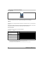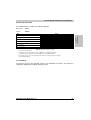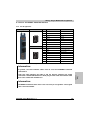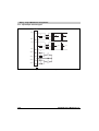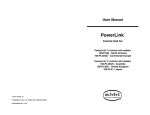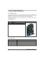
1
Technical Data • ACOPOS Plug-in Modules 2.4 AC112 - ETHERNET Powerlink Interface 2.4.1 General Description The AC112 plug-in module can be used in an ACOPOS slot. The module is equipped with an ETHERNET Powerlink interface. This fieldbus interface is used for communication and setting parameters on the ACOPOS servo drive for complex and time critical applications. The plug-in module is set up as a 2x hub. This makes it easy to establish a device to device connection (line topology). 2.4.2 Order Data Model Number Short Description Image Plug-in Module 8AC112.60-1 ACOPOS plug-in module, ETHERNET Powerlink interface Table 21: Order data for AC112 2.4.3 Technical Data Product ID 8AC112.60-1 General Information C-UL-US Listed Module Type Slot Power Consumption Yes ACOPOS plug-in module Slot 1 Max. 2.5 W Table 22: Technical data for AC112 58 ACOPOS User's Manual V 1.3.1 Technical Data • ACOPOS Plug-in Modules Product ID 8AC112.60-1 Powerlink Interface Connection, Module Side 2 x RJ45 socket Indications Status LEDs Electrical Isolation ETHERNET - ACOPOS Yes 100 m 1) Maximum Distance per Segment 100 Mbit/s Network Capable Yes Hub, 2x Yes Maximum Number of Hub Levels Chapter 2 Technical Data Baud Rate 10; see section 2 "ACOPOS™ Configurations" on Page 22 Cabling Topology Star or tree with level 2 hubs Possible Station Operating Modes Synchronous to Powerlink cycle Watchdog Function Hardware Software Yes (via ACOPOS servo drive) Yes (via ACOPOS servo drive) Operational Conditions Environmental Temperature During Operation 0 to +50 °C Relative Humidity During Operation 5 to 95%, non-condensing Storage and Transport Conditions Storage Temperature -25 to +55 °C Relative Humidity During Storage 5 to 95%, non-condensing Transport Temperature -25 to +70° C Relative Humidity During Transport 95 % at +40 °C Table 22: Technical data for AC112 (Forts.) 1) With a cycle time of 400 µs and 10 ACOPOS servo drives, the maximum total cable length is 200 m. 2.4.4 Powerlink Station Number Settings The Powerlink station number can be set using two HEX code switches: Image Code switch Powerlink station number n 16s position (high) o 1s position (low) The Powerlink station number change takes effect the next time the ACOPOS servo drive is switched on. Information: In principle, station numbers between $01 and $FD are permitted. However, station numbers between $F0 and $FD are reserved for future system expansions. For reasons of compatibility, we recommend avoiding these station numbers. Station numbers $00, $FE and $FF are reserved and are therefore not allowed to be set. Table 23: Setting the Powerlink station number ACOPOS User's Manual V 1.3.1 59 Technical Data • ACOPOS Plug-in Modules 2.4.5 Indications Figure 13: Status LEDs AC112 The status is indicated on the AC112 using one green (n) and one red LED (o). LED Test Immediately after resetting the module, both LEDs are switched off for 0.5 s, then switched on for 1.5 s. Then the green LED is cleared for one second and the following boot procedure. After proper initialization, the red LED is switched off and the green LED is switched on. Status of the LEDs The following timing is used for the indication diagram: Block size: 150 ms Status LED Error-free operation Display Green Red Fatal system error 1) Green Red Master has dropped out Green Red System stop 2) Green Red See System Stop Error Codes Table 24: Indication diagram for the AC112 status LEDs 1) This is a problem which cannot be repaired, the system can no longer carry out tasks correctly. This status can only be changed by resetting the module. 2) The red LED blinks an error code, the output of the error code occurs in 4 short (150 ms) or long (600 ms) phases. 60 ACOPOS User's Manual V 1.3.1 Technical Data • ACOPOS Plug-in Modules System stop error codes The following timing is used for the indication diagram: Block size: 150 ms Pause: 2000 ms Error Display Chapter 2 Technical Data Stack overflow RAM error Undefined address 1) Instruction fetch memory abort 2) Data access memory abort 3) Assertion failed 4) Programming failed 5) Table 25: System stop error codes 1) 2) 3) 4) 5) Access of non-existent address. Invalid memory access during instruction fetch (e. g. WORD access of add numbered address). Invalid memory access during data access (e. g. WORD access of add numbered address). This system stop code only occurs in debug mode. The condition for a software assertion was not fulfilled. Error during programming. 2.4.6 Firmware The firmware is part of the operating system for the ACOPOS servo drives. The firmware is updated by updating the ACOPOS operating system. ACOPOS User's Manual V 1.3.1 61 Wiring • Plug-in Module Pin Assignments 6.2 AC112 - ETHERNET Powerlink Interface 6.2.1 Pin Assignments Image X1 Pin 1 Description Function 1 RXD Receive Signal 2 RXD\ Receive Signal Inverted 3 TXD Transmit Signal 4 Shield Shielding 5 Shield Shielding 6 TXD\ Transmit Signal Inverted 7 Shield Shielding 8 X2 Pin 1 Shield Shielding Description Function 1 RXD Receive Signal 2 RXD\ Receive Signal Inverted 3 TXD Transmit Signal 4 Shield Shielding 5 Shield Shielding 6 TXD\ Transmit Signal Inverted 7 Shield Shielding 8 Shield Shielding Table 111: Pin assignments for AC112 - ETHERNET Powerlink Interface Information: Take care when plugging the cable in and out because otherwise the shield connection could break between the RJ45 plug and the cable shield which could then cause connection disturbances! Information: ETHERNET Powerlink cables must have crossover pin assignments. Unassigned wires cannot be omitted. ACOPOS User's Manual V 1.3.1 197 Chapter 5 Wiring In general, crossover Ethernet cables must be used for ETHERNET Powerlink connections! Wiring • Plug-in Module Pin Assignments 6.2.2 Input/Output Circuit Diagram X1, X2 RXD 1 75E RXD\ 2 TXD 3 75E Vcc TXD\ 6 Shield 4 Vcc 50E 50E Shield 5 50E 1n Shield 7 Shield 8 50E 50E 50E Figure 49: Input/Output Circuit Diagram AC112 198 ACOPOS User's Manual V 1.3.1