1
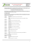
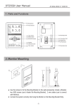
Expert I/O 1000
Hardware User Manual
Revision 4 | January 6, 2010
© 2008-2010 Dajac Inc. All Rights Reserved.
www.dajac.com
[email protected]
Expert I/O 1000
Hardware User Manual
Contents
EXPERT I/O 1000............................................................................................................2
PIN CONFIGURATION....................................................................................................2
USB...........................................................................................................................................3
DC IN........................................................................................................................................4
+B1/+B......................................................................................................................................4
+5V Output..............................................................................................................................4
+24V Input...............................................................................................................................4
Analog Outputs........................................................................................................................4
Motor Controllers....................................................................................................................4
Analog Inputs...........................................................................................................................5
Digital Outputs.........................................................................................................................5
Digital Inputs...........................................................................................................................5
EEPROM..........................................................................................................................5
MOUNTING......................................................................................................................6
ELECTRICAL SPECIFICATIONS....................................................................................6
Absolute Maximum Ratings....................................................................................................6
Electrical Characteristics........................................................................................................7
Rev. 4
-1-
1/6/10
Expert I/O 1000
Hardware User Manual
Expert I/O 1000
The Expert I/O 1000 is a USB connected I/O module. With this module, it is easy to use a PC to control
external devices. A couple common examples are industrial control and test bench automation.
The Expert I/O 1000 was designed to provide a PC digital inputs and outputs, analog inputs and outputs,
and motor control all through a single USB connection. All the interfaces are highly configurable, giving
the user flexibility in their use. The I/O includes 16 digital inputs, 16 digital outputs, 6 analog inputs, 2
analog outputs, and 2 DC motor control outputs.
An application programming interface (API) is provided that allows the user to write software that controls
the Expert I/O 1000 specifically for their needs. See the Software User Manual for details of this API.
When using the API, it is useful to know the Expert I/O 1000's model ID.
Expert I/O 1000 model ID: 1
The Hardware User Manual will focus on the hardware details only.
Pin Configuration
I/O connections to the EIO1000 are made through the use of pluggable screw terminals. Insert the wire for
the desired connection into the plug, which may be connected to the header if desired, and secure by
tightening the screw on the top of the plug. The user can use as many or as few connections as needed.
The pin configuration is shown below.
Rev. 4
-2-
1/6/10
Expert I/O 1000
Hardware User Manual
Pin
Function
Pin
Function
1
+B1
29
Digital Output - Port 2.0
2
+B
30
Digital Output - Port 2.1
3
GND
31
Digital Output - Port 2.2
4
+5V Output
32
Digital Output - Port 2.3
5
GND
33
Digital Output - Port 2.4
6
+24V Input
34
Digital Output - Port 2.5
7
Analog Output 1
35
Digital Output - Port 2.6
8
Analog Output 0
36
Digital Output - Port 2.7
9
Motor 0 Output (+)
37
Digital Output - Port 3.0
10
Motor 0 Supply Input
38
Digital Output - Port 3.1
11
Motor 0 Output (-)
39
Digital Output - Port 3.2
12
Motor 0 Supply GND
40
Digital Output - Port 3.3
13
Motor 1 Output (+)
41
Digital Output - Port 3.4
14
Motor 1 Supply Input
42
Digital Output - Port 3.5
15
Motor 1 Output (-)
43
Digital Output - Port 3.6
16
Motor 1 Supply GND
44
Digital Output - Port 3.7
17
Analog Input 5 GND
45
Digital Input – Port 1.7
18
Analog Input 5
46
Digital Input – Port 1.6
19
Analog Input 4 GND
47
Digital Input – Port 1.5
20
Analog Input 4
48
Digital Input – Port 1.4
21
Analog Input 3 GND
49
Digital Input – Port 1.3
22
Analog Input 3
50
Digital Input – Port 1.2
23
Analog Input 2 GND
51
Digital Input – Port 1.1
24
Analog Input 2
52
Digital Input – Port 1.0
25
Analog Input 1 GND
53
Digital Input – Port 0.7
26
Analog Input 1
54
Digital Input – Port 0.6
27
Analog Input 0 GND
55
Digital Input – Port 0.5
28
Analog Input 0
56
Digital Input – Port 0.4
57
Digital Input – Port 0.3
58
Digital Input – Port 0.2
59
Digital Input – Port 0.1
60
Digital Input – Port 0.0
USB
This is the connection back to the USB host. The host can be any device that has a USB host connection.
Typically a computer is used as the host.
Rev. 4
-3-
1/6/10
Expert I/O 1000
Hardware User Manual
DC IN
The power supply that ships with the Expert I/O 1000 is attached to this input to power the unit. If this
input is used, the +24V input must be left unconnected. See Section +24V Input. Connecting power to both,
the DC IN jack and the +24V input may result in damage to the Expert I/O 1000 and/or the power supplies.
+B1/+B
These inputs are used with the digital I/O to allow user-definable logic levels. See Section Digital Inputs
and Section Digital Outputs for details of how +B1 and +B are used.
+5V Output
This pin can be used to supply 5V to external devices. It is particularly useful for creating 5V logic levels
by connecting it to the +B1 and/or +B inputs.
+24V Input
If a 24V supply is available, it can be connected to this pin to power the Expert I/O 1000. When using this
pin, it is important to not use the DC IN jack. See Section DC IN. Connecting power to both, the DC IN
jack ad the +24V input may result in damage to the Expert I/O 1000 and/or the power supplies.
Analog Outputs
There are two independent analog outputs. Both have 12 bit precision and both are software configurable to
any of the following ranges.
• 0V to +5V
• 0V to +10V
• -5V to +5V
• -10V to +10V
• -2.5V to +2.5V
• -2.5V to +7.5V
Motor Controllers
Two independent motor controllers are provided. These controllers are capable of directly driving DC
brush motors.
Due to the large amount of power required by most motors, the motor controller interface has a separate
power supply connection for each motor. This also allows each motor to operate at a different supply
voltage.
To help prevent damage to the controllers, each has overcurrent and thermal warning/shutdown protection.
If the current exceeds approximately 10A, the controller will shutdown. Similarly, if the controller reaches
145 °C a thermal flag will be set that can be read through the USB. This allows the controlling software to
Rev. 4
-4-
1/6/10
Expert I/O 1000
Hardware User Manual
take action to reduce the temperature (such as slowing the motor). However, if the temperature continues to
rise, the controller will shutdown at 170 °C.
For both, current and temperature shutdown, the controller will automatically restart when the error
condition is cleared.
Analog Inputs
There are six 8-bit analog inputs. A separate ground connection is provided with each input to help reduce
noise issues.
Digital Outputs
Sixteen digital outputs are provided as two 8-bit ports (P2 and P3). Each of these outputs are push-pull,
giving them the ability to source and sink current. Additionally, the voltage level for logic high output is
software configurable to the following levels.
• +3.3V: This setting is available for both ports, P2 and P3.
•
+B: The logic high voltage is +B volts. This setting is only available for P2. See Section +B/+B1.
• +B1: The logic high voltage is +B1 volts. This setting is only available for P3. See Section +B/+B1.
Digital Inputs
Sixteen digital inputs are provided as two 8-bit ports (P0 and P1). Each input operates over a wide range
and each has a software configurable 100KΩ pull up or pull down. The pull voltage can be configured as
follows.
• None: The pull is disabled. This setting is available to both ports, P0 and P1.
• +3.3V: The input is pulled to 3.3V. This setting is available for both ports, P0 and P1.
• Ground: The input is pulled to ground. This setting is available for both ports, P0 and P1.
• +B: The input is pulled to +B volts. This setting is only available for P0. See Section +B1/+B.
• +B1: The input is pulled to +B1 volts. This setting is only available for P1. See Section +B1/+B.
The digital inputs have a state change notification feature. When an input changes state, a flag is set. This
flag can be read through the USB.
EEPROM
In addition to the I/O described above, the Expert I/O 1000 also includes 2 Kilobytes of user accessible
EEPROM. There are no restrictions on the use of this memory.
Rev. 4
-5-
1/6/10
Expert I/O 1000
Hardware User Manual
Mounting
The Expert I/O 1000 has a compact design and can be mounted on a DIN rail. However, it works equally
well on horizontal surfaces without the rail. When using DIN rail, use 35mm width with a minimum height
of 7.3mm and a thickness of 1.0mm or 1.5mm.
The physical dimensions of the Expert I/O 1000 are shown in Figure 1.
Figure 1: Expert I/O 1000 demensions.
The screw terminal plugs extend an additional 0.4” on both sides.
Electrical Specifications
Absolute Maximum Ratings
Maximum ratings are those values beyond which device damage can occur. Maximum ratings applied to
the device are individual stress limit values (not normal operating conditions) and are not valid
simultaneously. If these limits are exceeded, device functional operation is not implied, damage may occur
and reliability may be affected.
Rev. 4
-6-
1/6/10
Expert I/O 1000
Hardware User Manual
Digital Input Voltage.................................................... 36V
+B Voltage................................................................... 29V
+B1 Voltage................................................................. 29V
Digital Output Current................................................. 100mA
+5V Output Supply Current......................................... 200mA
Analog Output Current................................................. ±15mA
Analog Input Voltage................................................... 5V
Analog Input Impedance.............................................. 10KΩ
Motor Supply Voltage.................................................. 60V
Motor Continuous Current........................................... 3A
Motor Peak Current...................................................... 6A
Electrical Characteristics
Parameter
Supply Voltage (DC IN and +24V Input)
Supply Current (DC IN and +24V Input)
Min
Max
Units
22.8
25.2
V
625
mA
30
V
(2)
Digital Input Range
0
Digital Input HIGH Level Voltage
2.0
Digital Input LOW Level Voltage
V
1.5
V
27
V
50
mA
10
V
Analog Output Current
±10
mA
Analog Output Resolution
12
bits
5
V
8
bits
Digital Output Range
Digital Output Current
0
(1)
Analog Output Range
-10
Analog Input Range
0
Analog Input Resolution
Motor Supply Voltage
12
55
V
+B Voltage
3.3
27
V
+B1 Voltage
3.3
27
V
Notes:
1) Total current for an entire output port (P2, P3) cannot exceed 100mA.
2) Supply current will vary based on the loading of the outputs.
Rev. 4
-7-
1/6/10