1
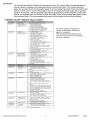
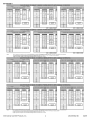
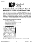
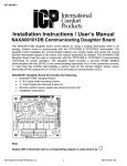
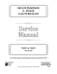
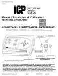
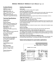
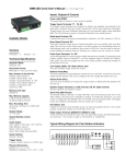
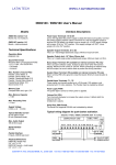
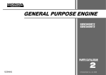
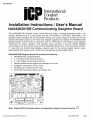
997-060180-7
Installation Instructions / User's Manual
NAXA00201DB
Communicating
Daughter
Board
The NAXA00201DB
daughter board control allows for using 4 existing thermostat wires in an
existing, finished home to communicate
with the TSTAT0406
& TSTAT0407
thermostats.
The
daughter board translates the communicated
heating and cooling needs and sends the normal
discrete thermostat outputs to the indoor and outdoor equipment as needed. The NAXA00201DB
Daughter Board must be used in conjunction with the TSTAT406 or TSTAT0407
Communicating
Thermostat
for proper operation.
The daughter board provides a two-wire RS485 ModBus
communication
link and 24VAC to the communicating
thermostat via a 4 wire connection scheme,
"L" input from the Comfort Alert Module, a sensor input for the remote outdoor sensor, seven
thermostat 24VAC outputs (W,G,Y,O,W2,Y2,H)
and status & communication LED's.
NAXA00201DB
Daughter Board Kit includes the following:
• NAXA00201DB
Daughter Board
• 6 - # 6 sheet metal mounting screws
• "L" Input Pigtail wire harness & wire nut
• Remote outdoor sensor pigtail wire harness & wire nuts
• Installation instructions (48206530200)
• VA Rating of 4.8 (200mA at 24 VAC)
• SPDT-NO Panel Mount Relay with 24VAC Coil
C
Note:
Output
Y2 W2
H
Y
G
W
O
LED's illuminate
International Comfort Products, Inc.
next to corresponding
1
outputs
in areas shown by -_
482 06 5302 00
02/09
997-060180-7
Daughter Board Terminals & Connections
See wiring diagrams for proper wiring and installation.
The following connections are provided in the P2 terminal block: (Power and Communication
Connections to Communicating
Thermostat)
P2 - Pin 1
"R"
24VAC hot power connection for communicating
thermostat
P2 - Pin 2
"GND" Ground connection for communicating
thermostat
P2 - Pin 3
"DX+" DX+ connection to the A+ Terminal on the communicating
thermostat
P2 - Pin 4
"DX-"
DX- connection to the B- Terminal on the communicating
thermostat
The following
P3 P3 P3 P3 P3 -
connections are provided in the P3 terminal block: (Outputs to the HVAC Equipment)
Pin 1
"O"
24 VAC thermostat output
Pin 2
"W"
24 VAC thermostat output
Pin 3
"G"
24 VAC thermostat output
Pin 4
"Y"
24 VAC thermostat output
Pin 5
"Not Used"
24 VAC thermostat output
The following
P4 P4P4 P4 P4 -
connections are
Pin 1
"H"
Pin 2
"W2"
Pin 3
"Y2"
Pin 4
"R"
Pin 5
"C"
The following
Hook-up)
P5P5P5P5-
connections
Pin
Pin
Pin
Pin
1
2
3
4
provided
24 VAC
24 VAC
24 VAC
24 VAC
24 VAC
are provided
in the P4 terminal block: (Outputs to the HVAC Equipment)
thermostat output
thermostat output
thermostat output
system power input
system common input
in the P5 Connector:
Status
Location for the Outdoor
Sensor
"OD"
Ground for Remote Outdoor Temperature Sensor
"OD"
Remote Outdoor Temperature Sensor input
"Not used"
"Not used"
The following connections are provided in the P8 Connector:
ALARM Output)
P8 - Pin 1
"Not Used"
-.... No Connect ....
P8 - Pin 2
"Not Used"
- - - No connect - - P8 - Pin 3
(Optional
"L....
(Optional
Connection
for the Comfort Alert
L" fault input from Comfort Alert Module
LED Operation
The LED labeled LED5 is a status LED that will provide a "heart beat" blink of this LED to indicate
that the NAXA00201 DB communicating
daughter board control is powered and working properly.
Communication
LED Operation
The LED labeled LED3 will be illuminated for 100mS each time a successful
is received from the TSTAT0406 or TSTAT0407 communicating
thermostat.
communications
packet
Thermostat
Call Output LED's Operation
There is an LED Output for each thermostat output from the daughter board. The corresponding
LED will illuminate any time the associated thermostat output is active.
•
LED 8 illuminates when "O" Output is energized
•
LED 7 illuminates when "W" Output is energized
•
LED 6 illuminates when "G" Output is energized
•
LED 4 illuminates when "Y" Output is energized
•
LED 9 illuminates when "H" Output is energized
•
LED 1 illuminates when "w2" Output is energized
•
LED 2 illuminates when "Y2" Output is energized
"L" Input from
Comfort
International Comfort Products, Inc.
Alert Module
to Daughter
Board
2
482 06 5302 00
02/09
997-060180-7
The Comfort Alert Module will transmit the active fault code. The Comfort Alert or thermostat
does not
have any effect on operation of the equipment during a Comfort Alert fault. The Comfort Alert fault
output can be wired directly to the daughter board or communicating
thermostat. When the Comfort Alert
Module is wired to the "L" input of the daughter board, it will recognize the fault output after it has been
active for 10 seconds. After the daughter board has recognized the active fault from the Comfort Alert
Module, the daughter board will forward the fault information to the communicating
thermostats via the
communication wires. The communicating
thermostat will then display the fault code as defined.
COMFORT
ALERT
TM
MODULE
FAULT CODES
Green "POWER"
Module has power
Supply voltage is present at module terminals
Red "TRIP"
Thermostat demand signal
Y is present, but the
compressor is not running.
1.
•
•
2.
3.
4.
5.
6.
1.
2.
•
•
•
•
•
•
3.
•
•
•
•
4.
•
•
5.
6.
7.
•
•
8.
Yellow "ALERT"
Flash Code 1
Long Run Time
Compressor is running
extremely long run cycles
Yellow "ALERT"
Flash Code 2
System Pressure Trip
Discharge or suction
)ressure out of limits or
compressor overloaded
Yellow
Flash
"ALERT"
Code 3
Compressor protector is open
Check for high head pressure
Check compressor supply voltage
Outdoor unit power disconnect is open
Compressor circuit breaker or fuse(s) is open.
Broken wire or connector is not making contact
Low Pressure switch open if present in system
Compressor contactor has failed open.
Low refrigerant charge
Evaporator blower is not running
Check blower relay coil and contacts
Check blower motor capacitor
Check blower motor for failure or blockage
Check evaporator blower wiring and connectors
Check indoor blower control board
Check thermostat wiring for open circuit
Evaporator coil is frozen
Check for low suction pressure
Check for excessively Iowthermostat setting
Check evaporator airflow (coil blockages or return air filter)
Check ductwork or registers for blockage
Faulty metering device
Check TXV bulb installation (size, location and contact)
Check if TXV/fixed orifice is stuck closed or defective
Condenser coil is dirty
Liquid line restriction (filter dner blocked if present in system)
Thermostat is malfunctioning
Check thermostat sub-base or wiring for short circuit
Check thermostat installation (location, level)
Comfort Alert Module failure
1. High head pressure
• Check high pressure switch if present in system
• Check if system is overcharged with refrigerant
• Check for non-condensable in system
2. Condenser coil poor air circulation (dirty, blocked, damaged)
3. Condenser fan is not running
• Check fan capacitor
• Check fan wiring and connectors
• Check fan motor for failure or blockage
4. Return air duct has substantial leakage
5. If Iow pressure switch present in system, check Flash Code
1 information
Short Cycling
Compressor is running
onty briefly
1. Thermostat demand signal intermittent
2. Time delay relay or control board defective
3. If high pressure switch present, go to Flash Code 2
information
4. If Iow pressure switch present, go to Flash Code 1
information
Yellow "ALERT"
Flash Code 4
Locked
Yellow
Flash
"ALERT"
Code 5
Open
Circuit
Yellow
Flash
"ALERT"
Code 6
Open
Start
1. Run Capacitor has failed
2. Low line voltage (contact utility if voltage disconnect is tow)
3. Excessive liquid refrigerant in compressor
4. Compressor bearings are seized
• Measure compressor oil level
1. Outdoor unit power disconnected
2. Compressor circuit breaker or fuse(s) open
3. Compressor contactor has failed open.
• Check compressor contactor wiring and connectors
• Check for compressor contactor failure (burned, pitted or
open)
• Check wiring and connection between supply and
compressor
• Check for tow pilot voltage at compressor contactor coil
4. High pressure switch is open and requires manual reset
5. Open circuit in compressor supply wiring or connections
6. Unusually tong compressor protector reset time due to
extreme ambient temperature
7. Compressor windings are damaged
• Check compressor motor winding resistance
1. Run capacitor has failed
2. Open circuit in compressor start winding or connections
• Compressor start winding is damaged
• Check compressor motor winding resistance
Rotor
Circuit
Yellow "ALERT"
Flash Code 7
Open Run Circuit
Current only in start
circuit
Yettow"ALERT"
Welded
Flash
Code 8
Yettow"ALERT"
Flash
Code
9
Contactor
Low Voltage
Controt circuit < 17
VAC
International Comfort Products, Inc.
Flash Code number corresponds to a
number of LED flashes, followed by a
pause then repeated.
TRIP and ALERT LED's flashing at the
same time means control circuit voltage is
too low for operation.
1. Open circuit in compressor run wiring or connections
• Check wiring and connectors between supply and the
compressor "R _'terminal
2. Compressor run winding is damaged
• Check compressor motor winding resistance
1. Compressor contactor has failed closed
2. Thermostat demand signal not connected to module
1. Control circuit transformer is overloaded
2. Low line voltage (contact utility if voltage at disconnect
tow)
• Check wiring connections
3
is
482 06 5302 00
02/09
_ERM_TAT
........................................
C......................................
W2
Wt
H
O/B
Yt
L
:::t
A+
%_1%%_
R I
:::t %T%RI
GND
OD
ID
_'U
*SMRV* "C" SERIES
*gMRV* "D" SERIES
REQUIRED
..............
OR NEWER
OR NEWER
*SMPV* "C" SERIES OR NEWER
*9MPV* "D" SERIES OR NEWER
OPTIONAL
i
_i
i
i
i i
i
iii
i
i
i:iili
;i
i
ii
;
i
i
i
_ERM_TAT
........................................
C......................................
W2
F
wt
H
° T%RI
'67E
O/B
L-
Yt
G
L
O TyoORI
A+
GND
OD
ID
GND
Notes:
The "L" Output from the Heat Rump or A/C Unit can be wired to either the NAXA00201DB
The Outdoor Sensor can be hooked directly to the NAXA0O201DB Daughter Board or the
A pigtail wiring harness is supplied with the NAXAOO2Ol DB Daughter Board for connection
A pigtail widng harness is supplied with the NAXA0O201DB Daughter Boat'd for connection
*SMPV* "C" SERIES OR NEWER
*gMRV* "D" SERIES OR NEWER
Daughter Board or the TSTATO4O6 or TSTATO407 Thermostats
TSTATO406 or TSTATO4O7 Thermostats for proper operation.
to its "L" input.
to its "OD" inputs.
O!
REQUIRED
..............
A+
GND
OD
ID
GND
*SMPV* "C" SERIES OR NEWER
*9MPV* "D" SERIES OR NEWER
for proper operation
_ _I',I!T$ i/O
OPTIONAL
_AT
i
-_I
i
i
i
i
i
i
i
c
c
R
R
0_
i
i
i
i
I
i
i
i
i
i
i
i
DX+
i
DXi
::::::t °S%_I
:::::::::1
°_T%°°_
I
GND
BAU_B
E_ BOARB TO FA_I_
..............
REQUIRED
i
i
C
i
R
i
i
DX+
DX-
-::-----.j
os%oo_
I
I
TO GENERIC B_W]RIN_
:(_E_
TO _tTS
i10_ A N UA _:FO_ :SP_FI_S)
OPTIONAL
c
....
i
i
R
_Z
i
i
i
i
i
--
i
i
---
i
I
=:1
I
DX+
DX-
J
::t
%_1%0_R
DX+
DX-
--I
j
i
i
::::::I
i
i
I::
i
i
i
i
_'_° I
Notes:
The "L" Output from the Heat Pump or A/C
The Outdoor Sensor can be hooked directly
A pigtail wiring harness is supplied with the
A pigtail wiring harness is supplied with the
Unit can be wired to either the NAXA002Ol DB Daughter Board or the TSTAT0406 or TSTAT04O7 Thermostats
to the NAXAOO201DB Daughter Board or the TSTATO4O6 or TSTATO407 Thermostats for proper operation
NAXA0O2Ol DB Daughter Board for connection to its "L" input
NAXAOO2Ol DB Daughter Board for connection to its "QD" inputs
International Comfort Products, Inc.
4
for proper operation.
482 06 5302 00
02/09
997-060180-7
.........
i
i
VARIABLESPEED(DEHUM)
i
C
ii t1
iii
___
}
--
= REQUIRED
i
H
i i
ii ii
i i
i
i
i
i
i
ii
ii
i
i
i
ii ii
i
i
i
i i
i
i t ii
i :
i :: i
i i
[
l
O
O
l
--(---(--
SPDT
RELAY
SRELA¥
D,; HUMID,FIER
HUMIDIFIER
HUMIDIFIER
115v
115v
___Sv
NOTE:A separateff5v supply should beused,
NOTE:A separate 'i'i5v supply should beused,
NOTE:A separate f15v supply should beused,
NOTE:Whenusing a humidifierona HPconnectto hot water,
NOTE:A separate115vsupply shouldbe used,
NOTE:When usinga humidifieron a HPconnectto hot water.
NAXA00201DB
Drill Template
Directions:
1. Cut Template out along dotted lines.
2. Tape template over the sheet metal area to be drilled.
3. Drill four holes using a #32 drill bit (.1160") through the four dark circles denoted on the template.
4. Remove the template from the drilled area.
5. Mount the NAXAOO201DB Control with four #6 sheet metal screws included in the kit.
Note:
- Ensure that are to be drilled is clear of any gas lines or wiring harnesses prior to drilling.
Drill Holes-
2 places
International Comfort Products, Inc.
Drill Holes-
5
2 places
482 06 5302 O0
02/09