1
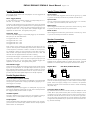
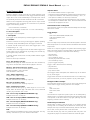
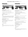
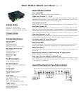
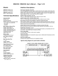
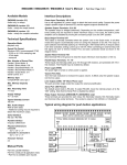
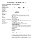
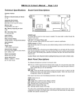
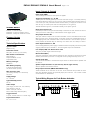
EM34A / EM34A-R / EM34A-X User’s Manual
Page 1 of 6
Inputs, Outputs & Controls
Power Light (PWR)
The power light is turned on when power is applied.
Trigger Input Terminals: T1 - T4, GD
These inputs are internally pulled up to 3.3Vdc and seen as logic “1” if actively driven by
a DC signal within the range of 3.3V to 5V (for units purchased before October 2015) or
3.3V to 40V (for units purchased in/after Octorber 2015), or simply left undriven. To be
seen as logic “0” these inputs must be actively driven to 0V (ground).
Available Models
EM34A: no internal relays.
EM34A-R: 4 relays for simple control.
EM34A-X: 4 relays for advanced control.
Firmware Version
1.4
Technical Specifications
Operation Mode
playback only
Sound File Format
MP3 (ISO 11172-3 up to 44.1KHz)
Max. Number of Sound Files
Direct Mode: 4
Sequential Mode: 4 x 99
Script Mode: 999
Memory Card Type
SD/SDHC
Max. Memory Capacity
2 GB for SD (FAT/FAT16)
32 GB for SDHC (FAT32)
Max. Recording Time
(Assuming 128 kbps on a 2GB card)
33 hours
Supply Voltage
12 ~ 30 VDC
Typical Standby Current
60 mA
Audio Output
(30V supply, 8 Ohm load, 10% THD+N)
High efficiency class D
Stereo: 15W per channel
Mono: 55W bridge tied load (BTL)
Trigger Interface
4 inputs, contact closure or 3.3V/5V logic
Physical Dimensions
5.1’’ x 4.0’’ x 1.4”
The GD terminal is ground, connected internally to the power ground.
Reset Input Terminal: RS
Pull this input down to the ground momentarily to reset the unit. Min. duration is 100 ms.
This input has the same pull-up characteristics as the trigger inputs.
Busy Output Terminal: BY
This open collector output from an internal transistor can be controlled with more flexibility if the unit runs in the Script mode. In all other modes it is automatically turned on
while playing audio, with a maximum sink current of 200 mA. It can be used to synchronously activate an external relay for switching on a device such as a lamp or a motor.
Power Input Terminals: V+, GD
Use a well regulated DC power supply to obtain the best sound quality. Connect the power
supply’s positive output to terminal V+, and the negative output to terminal GD.
Line Output (LINE): 1/8” Stereo Phone Jack
This jack provides single ended line output.
Balance Knob (BAL)
This knob adjusts the output balance between the two channels. It should be set at the
middle (center detent) if the unit is configured for BTL (bridge tied load) mono out.
Volume Knob (VOL)
Turn this knob clockwise to increase the output volume. It affects both the speaker and
the line out.
Speaker Output Terminals: LF (left channel), GD, RT (right channel)
See the Speaker Connections section.
Relay Output Terminals (EM34A-R & EM34A-X only)
These terminals are on the back of the unit. Three terminals are provided for each
relay: NC (Normally Closed), NO (Normally Open) and Common. The contact is rated
at 12A/120VAC or 10A/24VDC.
Typical Wiring Diagram for Push Button Activation
EM34A / EM34A-R / EM34A-X User’s Manual
Page 2 of 6
Parallel Trigger Modes
Parallel Trigger Polarity
The Trigger Mode defines how the playback is to be triggered via
the parallel inputs.
Close Contact
Input is continuously triggered when it’s at 0V (ground), e.g. while
a ground-connected push button is pressed and held down.
Direct Trigger (default)
In this mode each input directly triggers a corresponding file: T1 =
File 001, T2 = File 002, ......, T4 = File 004.
A trigger is valid when the input is shorted to the ground for at least
50 ms. The Direct Trigger is prioritized from T1 (the highest) to T4
(the lowest). However, it does not mean a higher priority input can
interrupt a lower one. It only means that if multiple triggers are
applied at the same time, the highest priority wins.
Sequential Trigger
Use the Sequential Trigger to sequentially trigger up to 99 different
files per input as described below.
T1
T2
T3
T4
triggers
triggers
triggers
triggers
File
File
File
File
001
201
301
401
~
~
~
~
099
299
399
499
Open Contact
Input is continuously triggered when it’s left open or at 3.3V/5V,
e.g. while a ground-connected push button is up.
Make Contact
Input is triggered one time as it goes from 3.3V/5V to 0V, e.g. when
a ground-connected push button is pressed down.
Break Contact
Input is triggered one time as it goes from 0V to 3.3V/5V, e.g. when
a ground-connected push button is released.
Speaker Connections
Regular Stereo
Virtual Surround Stereo
Each trigger on the same input activates the next file in the sequence. The sequence automatically restarts when either the end
of the sequence is reached or there is a break in the sequence.
For example, if there are only three files on the flash card: 001,
002, and 004, the system will only sequence from 001 to 002. File
004 will never be played because File 003 is missing.
The Sequential Trigger is prioritized from T1 (the highest) to T4
(the lowest). However, it does not mean a higher priority input can
interrupt a lower one. It only means that if multiple triggers are
applied at the same time, the highest priority wins.
Round-Robin Trigger
This mode is very similar to the Direct Trigger mode except that the
inputs are not prioritized. So if multiple inputs are tied to ground
then their files will be played one after another, instead of just the
highest priority one. Round-Robin mode can only be used in conjunction with Non-interruptible Playback and Script Playback.
The left channel signal is internally inverted and that’s why the left
speaker has an inverted polarity for regular stereo output. If the left
speaker is not inverted then the output is virtual surround stereo.
Regular Mono
BTL Mono (4X Power Booster)
Parallel Playback Modes
Non-interruptible Playback (default)
The file is played once per trigger. The playback is not interruptible
except by the system reset. Looping is possible by applying a constant trigger on the input.
Interruptible Playback
The file is played once per trigger if not interrupted. Any input can
interrupt the playback except that an input cannot interrupt itself if
the Trigger Polarity is either Close or Open.
Holdable Playback
The file is played for as long as the input is triggered, looping if
necessary. It is not interruptible except by the system reset.
Script Playback
This mode allows many alternative playback options such as background music and random play. Please see the Script Playback
Mode section for descriptions.
Since BTL mono provides four times the output power of regular
mono at the same supply voltage, it is often used to boost the output
power when the supply voltage is low. However, the speaker
impedence should not be lower than 8 Ohms to avoid overloading
the power amp.
Converting Stereo To Mono
By default the left channel is inverted internally to facilitate the use
of BTL Mono (4X power booster). But if the Line Output is to be
converted to mono with a stereo-to-mono patch cord then the inverted left channel will cancel out most, if not all, of the right channel. In this case, the fourth letter ‘R’ must be added to the system
configuration file (MODE.TXT) to prevent the left channel from being inverted internally.
EM34A / EM34A-R / EM34A-X User’s Manual
Script Playback Mode
Instead of playing a single sound file, the Script Playback mode
executes a script of commands for each trigger. Note that the Busy
output will not turn on/off automatically in the Script mode. It must
be specifically turned on/off with the BN and the BF commands.
Written in the configuration file using plain text, the script consists
of multiple lines each containing the commands for a particular
trigger in the following format:
?nnn=Command1,Command2...
Here “nnn” is the trigger number and “?” is one of the following:
N - Non-interruptible
This trigger is not interruptible.
I - Interruptible
This trigger can be interrupted by another trigger but not itself.
H - Holdable
Execution continues for as long as the trigger is applied, repeating
if necessary. Stops immediately when the trigger is removed.
In the DS and RS modes, there are 4 direct triggers (001 ~ 004,
corresponding to T1 ~ T4).
In addition to the direct triggers, there are also indirect triggers. An
indirect trigger can be activated only by jumping from another trigger using the Jump command.
In the DS and RS modes, there are 995 possible indirect triggers
(005 ~ 999).
These are the script commands:
Fnnn - play file #nnn one time
Example: F168 plays file #168. Note that the next command (if
any) will not be executed until the file has played to the end.
Wnnnnn - wait nnnnn units of 0.1 second
Maximum value for nnnnn is 65535 (6553.5 seconds).
Example: W00020 = wait 2 seconds.
Note: W00000 = wait forever.
Jnnn - jump to trigger #nnn
Example: J007 jumps to trigger 007.
BF - turn off the Busy output
Use this command to turn the Busy output off.
BN - turn on the Busy output
Use this command to turn the Busy output on.
Rgnn - random play one time
Play a random file from group g, within range 01 to nn. For example, R015 will random play a file within 001 to 015; R208 will
random play a file within 201 to 208.
XNn - turn on relay #n (EM34A-R & EM34A-X only)
Example: XN3 turns on relay #3.
XNN - turn on all relays (EM34A-R & EM34A-X only)
Example: XNN turns on all relays.
XFn - turn off relay #n (EM34A-R & EM34A-X only)
Example: XF2 turns off relay #2.
XFF - turn off all relays (EM34A-R & EM34A-X only)
Example: XFF turns off all relays.
END
Always add the word END at the end of the entire script. You may
add any comments for your own reference after END.
Page 3 of 6
Important Notes
- All command letters must be in upper case.
- Script lines must be separated by carriage returns (the Enter key).
- A script line is limited to 128 characters, excluding ‘=’ and ‘,’. If
more space is needed, use the Jump command.
- A command is always fully executed before the next one starts.
For example, the command after ‘F001’ will not be executed until
the 001 file has played to the end.
Automatic Execution of Script 000
Upon powerup or reset, the system will automatically executes script
000 once if it exists.
Script Example
DS
N001=F007,W00030,BN,R926,BF,J168
I168=F001,W36000,J168
H033=F273
END
DS is not really a script command, but it tells the system to enter the
Direct Script mode. You can also use RS to enable the Round-Robin
Script mode.
When the T1 input is triggered, the system start executing trigger
N001. Since this trigger is non-interruptible, it will always executes
to the end. Trigger N001 is executed as the following:
-
play file #007,
wait 3 seconds,
turn on the Busy output,
random play a file within 901 to 926,
turn off the Busy output,
jump to trigger 168 (I168).
Trigger I168 is executed as the following:
- play file #001,
- wait 60 minutes,
- jump back to itself.
Since trigger I168 is interruptible, this endless loop can be broken
by any future trigger.
Trigger H033 will never be executed because it is an indirect trigger in the DS mode, yet it is not jumped to by any other trigger.
Background Music Example
The automatic execution feature can be used to play background
music while no trigger is being executed. For example,
DS
I000=F123,J000
N001=F001,J000
END
Here file #123 is looped from power-up but can be interrupted by
trigger inputs T1. The J000 command at the end of script 001 jumps
to script 000, so file #123 starts to loop again (although from the
beginning instead of where it left off).
Random Play Consideration
All files within a random range must exist, or the system will play
nothing when a non-existing file is selected for random play. For
example, the script command R926 randomly selects a file within
901 to 926, so every file from 901 to 926 must exist.
Note that random play does not guarantee that every file in the
range will be played once before it selects the same file again.
EM34A / EM34A-R / EM34A-X User’s Manual
Page 4 of 6
System Configuration File
Relay Control (EM34A-R / EM34A-X only)
By default, the system works in the following mode without a configu
ration file:
The relays are controlled differently in different modes:
Trigger Input: Parallel
Trigger Mode: Direct
Playback Mode: Non-Interruptible
Trigger Polarity: Close Contact
To operate the system in any other modes, you need to create a
plain text file called “MODE.TXT” with a line of four letters:
First Letter: Trigger Mode
D = Direct
S = Sequential
R = Round Robin
Second Letter: Playback Mode
N = Non-interruptible
I = Interruptible
H = Holdable
S = Script
Third Letter: Trigger Polarity
C (or no letter) = Close Contact
O = Open Contact
M = Make Contact
B = Break Contact
Fourth Letter: R or (none)
By default the left channel is inverted internally to facilitate the use
of BTL Mono (4X power booster). But if the Line Output is to be
converted to mono with a stereo-to-mono patch cord then the inverted left channel will cancel out most, if not all, of the right channel. In this case, add this letter ‘R’ to prevent the left channel from
being inverted internally.
For Script modes, enter the script starting from the second line. Be
sure to add the word END at the end of the Script.
After editing the configuration file, be sure to save it as a “plain text
file”, “ASCII text file”, or simply “text file”. The system may not work
if the configuration file is not created properly.
File Number Assignment
Sound files on the flash card must be assigned a unique file number for identification purpose. The file number must be a three digit
number within the following range:
For Direct Trigger: 001 ~ 004
For Sequential Trigger: 001 ~ 099 (for T1), 201 ~ 499 (for T2 ~ T4)
Simply add the file number to the beginning of the original filename,
e.g. “001tiger.wav”. Note that if the flash card is formatted with FAT
(FAT16) and you want to store the maximum number of files (511)
on the card, you should keep the filenames (including the file number) within 8 characters and use only upper case letters and numbers. If the flash card is formatted with FAT32 then you may use
any filename that Windows allows.
QSA mode (EM34A-X only)
Relays are pre-programmed for synchronized activations during
audio playback by using the Windows based, user friendly QSAplay
program. A PC is needed for programming only, but not for the
actual operation.
Script mode
Relays are controlled by script commands. Please see the Script
Mode section for details.
All other modes
A relay will turn on when the corresponding file is being played.
Relay #1 corresponds to file #001, relay #2 corresponds to file
#002, and so on. For example, relay #4 will be turned on when file
#004 is being played.
Trouble Shooting Guide
1. No sound.
a. File numbers are not assigned properly.
b. The system is in the wrong mode due to missing or incorrect
configuration file.
c. If the flash card is inserted when the power is on, the system
may not work. To fix this problem, recycle the power or use the
RS input to reset the system.
d. The output volume may have been set too low. Try turning it up.
2. Plays the wrong file.
a. File numbers are not assigned properly.
b. The system is in the wrong mode due to missing or incorrect
configuration file.
3. Noisy playback.
The speed of the flash card is too slow. Use a faster flash card or
convert the file to a lower bit rate.
EM34A / EM34A-R / EM34A-X User’s Manual
Application Example
Triggering with Normally Open Push Buttons
Page 5 of 6
Notes
- Playing stops as soon as the button is released. If the same
button is pressed again later, playing re-starts from the beginning of the file instead of where it left off.
- If both buttons are held down, button #1 prevails. To play both
sounds alternately when both buttons are held down, use the
RH mode.
5. Play different sounds each time when the same button is
pressed.
1. Play without interruption.
Intended Operation
- Press button #1 to play file #001 once.
- Press button #2 to play file #002 once.
- When playing, pressing any button has no effect.
Required Text in MODE.TXT
None, this is the default mode (DN).
Notes
- The button can be released or held down when playing.
- If the button is held down when the playback finishes, the
sound will be played again.
- If both buttons are pressed or held down at the same time,
button #1 prevails.
2. Allow interruption during playback.
Intended Operation
- Press button #1 to play file #001 once.
- Press button #2 to play file #002 once.
- Playing can be interrupted by pressing any other button.
Required Text in MODE.TXT
DI
Notes
- When playing, pressing the same button again has no effect.
3. Play the sound only once even if the button is held down.
Intended Operation
- Press button #1 to play file #001.
- Press button #2 to play file #002.
- Don’t repeat the sound even if the button is held down.
Required Text in MODE.TXT
DS
N001=F001,J888
N002=F002,J888
H888=J888
END
Notes
- The system will stay in the “H888=J888” endless loop for as
long as the button is held down.
4. Play only when the button is held down.
Intended Operation
- Press & hold button #1 to play file #001.
- Press & hold button #2 to play file #002.
Required Text in MODE.TXT
DH
Intended Operation
- Press button #1 to play file #001 the first time, file #002 the
second time, and etc.
- Button #2 sequences through file #201, #202...
- When playing, pressing any button has no effect.
Required Text in MODE.TXT
SN
Notes
- Up to 99 files can be assigned to each button and file numbers
but be consecutive.
- To allow playback interruption, use the SI mode.
- To play only when the button is held down, use the SH mode. In
the SH mode, the same sound will repeat for as long as the
button is held down. To advance to the next sound, the button
must be released first.
6. EM34A-R: Turn on a single, different relay for each sound.
Intended Operation
- Turn on relay #1 when playing file #001.
- Turn on relay #2 when playing file #002.
Required Text in MODE.TXT
Only the mode letters are required, for example: DH.
7. EM34A-R: Turn on multiple relays for each sound.
Intended Operation
- Press button #1 to play file #007 and turn on relays #1 & 2.
- Press button #2 to play file #008 and turn on relays #2 & 3.
Required Text in MODE.TXT
DS
N001=XN1,XN2,F007,XFF
N002=XN2,XN3,F008,XFF
END
Notes
- XFF is used to turn off all relays.
8. EM34A-X: Pre-program relays for synchronized activations
during audio playback.
The relays will be activated automatically when playing QSA files.
There is no required text in MODE.TXT.
9. Very weak or no audio from Line Output when it’s converted
to mono with a stereo-to-mono patch cord.
Add the fourth letter ‘R’ in MODE.TXT. See System Configuration
File for details.
EM34A / EM34A-R / EM34A-X User’s Manual
Page 6 of 6
Application Example
Application Example
Automatic Playback on Power-up
Triggering with Normally Closed Switches & Sensors
1. Repeat continuously on power-up.
Intended Operation
- Play file #001 on power-up if switch #1 is closed.
- Play file #002 on power-up if switch #2 is closed.
.........
- Play file #004 on power-up if switch #4 is closed.
- If more than one switch is closed, play all corresponding files
sequentially.
- Repeat the file(s) until power is turned off.
Required Text in MODE.TXT
RN
Notes
- If priority is required, use DN instead of RN. In this case switch
#1 has the highest priority, switch #2 has the second highest
priority, and switch #8 has the lowest priority. If more than one
switch is turned on, only the file for the switch of the highest
priority will be played.
2. Repeat at intervals on power-up.
Intended Operation
- Same as the example above but play files at fixed intervals.
- Only files with corresponding switches closed will play.
Required Text in MODE.TXT
RS
N001=F001,W06000
N002=F002,W06000
.....
N008=F008,W06000
END
Notes
- W06000 is a delay loop of 6000 x 0.1 second = 10 minutes, so
the file(s) will be played at an interval of 10 minutes, one file at a
time.
1. Play when the switch/sensor opens, with no priorities.
Intended Operation
- Play file #001 when sensor #1 opens.
- Play file #002 when sensor #2 opens.
- Repeat the sound for as long as the sensor is open.
- If multiple sensors are open at the same time, play all corresponding files sequentially.
Required Text in MODE.TXT
RNO
Notes
- Unused inputs must be connected to the ground, as shown in
the wiring diagram.
2. Play when the switch/sensor opens, with priorities.
Intended Operation
- Same as the example above, but if multiple sensors are open at
the same time, the sensor of the highest priority prevails.
Required Text in MODE.TXT
DNO
Notes
- The sensor connected to T1 has the highest priority, and the
sensor connected to T8 has the lowest priority.
3. Play when the switch/sensor opens, but don’t repeat.
Intended Operation
- Play file #001 when sensor #1 opens.
- Play file #002 when sensor #2 opens.
- Do not repeat the sound.
Required Text in MODE.TXT
DSB
N001=F001,J999
N002=F002,J999
H999=J999
END
Notes
- The system will stay in the “H999=J999” endless loop for as
long as the sensor is open. The system will not respond to other
sensors until this one is closed.