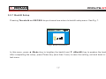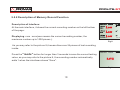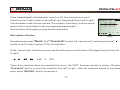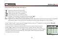
1
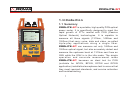
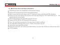
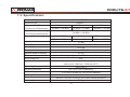
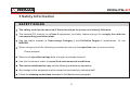
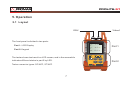
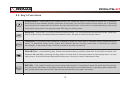
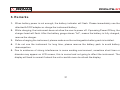
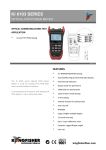
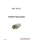
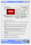
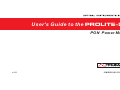
User's Guide to the PROLITE-57
PON Power Meter
v1.0
0 MI2029 (01/12/2014)
PROLITE-57
1. Introduction
1.1 Summary
2008-08-22 17:00:01
1310nm
ONU
1490nm
OLT
1550nm
VIDEO
1.2
- 4.5
-15.0
dBm
Pass
dBm
warning
dBm
Fail
mode
Threshold
dBm/dB
Time
REF/SEL
PROLITE- 57 is a portable, high quality PON optical
power meter. It is specifically designed to meet the
rapid growth of FTTx market with PON (Passive
Optical Network) technologies. It is capable to
measure all three signals (1310nm, 1490nm and
1550nm) that carry voice, data and video, so-called
t r i p l e - p l a y a p p l i c a t i o n s a l o n g a s i n g l e f i b e r.
PROLITE- 57 can measure not only 1490nm and
1550nm optical signal, but also accurately detect and
measure the upstream burst at 1310nm sent from an
ONU while the ONU is in the idle mode. The simple
operation and accurate measurement make
PROLITE- 57 becomes an ideal tool for PON
(suitable for APON, BPON, EPON and GPON
application) installation/acceptance test to ensure that
they meet required standards, and service activation
and troubleshooting.
1
PROLITE-57
1.2 Main Function and Specifications
Cost efficient palm size designed for field and lab testing.
Support P/F measurement and normal measurement.
Easy-to-use interface with large color TFT display for easy visibility and LED indicators.
Simply connect-and-display the results of all three wavelengths (1310/1490/1550 nm) of
PON
signals with two optical ports
Detect and measure the upstream burst at 1310 nm.
Support APON, BPON, EPON and GPON networks.
Pass, Fail and Warning indicators for easy view of signal condition.
User definable threshold value (up to 10 sets) Auto power shut off.
Low battery warningUSB interface.
Real-time clockUnit runs either by Ni-MH battery for more than 20 hours continuously work or
AC/DC adapter.
2
PROLITE-57
1.3 Specification:
Connector Type
SC/APC, ST/APC
InGaAs
Detector type
Measurement Range
(Continuous Datastream)
1310 nm
1490 nm
-40 dBm~+10 dBm
-40 dBm~+10 dBm
1550 nm
-40 dBm~+20 dBm
Burst measurement range
-30 dBm~+10 dBm
(1310 nm bursted signal)
Spectral Passband
1310 nm
1490 nm
1480 nm~1550 nm
1260 nm~1360 nm
Insertion Loss
1.5 dB
Accuracy
±0.5 dB
Linearity
±0.2 dB
Display
2.8 inch TFT LCD
Refresh Rate of Display
Threshold
2.5 Hz
10 sets(configured via PC-based software)
Auto Power-off
Number of Ports
1550 nm
1539 nm~1565 nm
Yes
2 ports. One for 1310 nm (ONU)
and one for 1490 nm / 1550 nm (OLT)
Operating Temperature
Relative Humidity
Power Supply
-10 to +50°C
0%~95%,non-condensing
1.2V*4pcs Ni-MH AA;12V AC/DC Adapter
Battery life
>20 hours
Dimension
190 mm*105 mm*55 mm(L*W*H) with rubber protector
Net Weight
700 g
3
PROLITE-57
3 Safety Information
SAFETY RULES
The safety could not be assured if the instructions for use are not closely followed.
The external DC charger is a Class II equipment, for safety reasons plug it to a supply line with the
corresponding ground terminal .
Use the mains adapter in Overvoltage Category I and Pollution Degree 1 installations. To use
INDOOR .
When using some of the following accessories use only the specified ones to ensure safety:
Power adapter
Observe all specified ratings both of supply and measurement.
Use this instrument under the specified environmental conditions .
The user is not allowed to carry out the following maintenance operations:
Any change on the equipment must be carried out exclusively by technical staff.
Follow the cleaning instructions described in the Maintenance paragraph.
4
PROLITE-57
Symbols related with safety:
Discharged batteries
DIRECT CURRENT
ON (Supply)
ALTERNATING CURRENT
OFF (Supply)
DIRECT AND ALTERNATING
DOUBLE INSULATION
(Class II protection)
GROUND TERMINAL
CAUTION
(Risk of electric shock)
PROTECTIVE CONDUCTOR
CAUTION REFER TO MANUAL
FRAME TERMINAL
FUSE
EQUIPOTENTIALITY
EQUIPMENT OR COMPONENT
TO BE RECYCLED
1.- When the battery power is almost out, there will be a
warning of indicator keeps blinking, then please replace
the batteries or plug in AC adapter to charge batteries.
2.- Please make sure that you have turned the instrument
on before charge the batteries, unplug the AC adapter
when the batteries are fully charged.
3.- Please make sure the batteries are well placed
before charge them.
4.- To eliminate the possibility of acid leakage, please
take out the batteries if the unit will not be used for a long
time
Specific Precautions
Never look directly into optical outputs or a fiber while the
equipment is on.
Invisible laser beam may damage your eyes.
Descriptive Examples of Over-Voltage Categories
Cat I
Low voltage installations isolated from themains.
Cat II
Portable domestic installations.
Cat III
Fixed domestic installations.
Cat IV
Industrial installations.
5
AC operation
If the instrument is mainly used at one location, e.g. in a
laboratory or test department, the AC adapter can be
used to power it instead of batteries. There is a DC input
jack on the left side of the PL-57 instrument casing into
which the output cable of the AC adapter is plugged. And
when the AC adapter is plugged in, the AC Indicator on
the LCD will be displayed.
Note:
1.- Power is supplied by the AC adapter even if battery is
fitted. And the battery indicator is not displayed on the
screen when AC adapter is plugged.
2.- Make sure that the operating voltage of the AC
Adapter / Charger is the same as the local AC line
voltage.
PROLITE-57
4. Preparing for Operation
Unpacking the instrument
Packing material
We suggest that you keep the original packing material. Using the original packing material is your
guarantee of protecting the instrument during transit.
Checking the package contents
The standard accessories of PROLITE-57 are as follows:
Main unit
Carrying Case
User's Guide
3 Ferrules
Case strap
4*Ni-MH Batteries
CD(software)
2 SC & ST adaptors
USB-USB mini cable
AC Adapter
Checking for damage in transit
After unpacking the instrument, check to see whether it was damaged in transit. This is particularly likely
if the outer casing is clearly damaged. If there is damage, do not attempt to operate the instrument or to
repair it without authorization. Doing so can cause further damage and you may lose your warranty
qualification.
6
PROLITE-57
5. Operation
5.1 Layout
ONU
Video/OLT
The front panel is divided in two parts:
2008-08-22 17:00:01
1310nm
Part I – LCD Display
ONU
1490nm
OLT
Part II - Keypad
1550nm
VIDEO
The tester shows test result on LCD screen, and in the meanwhile
indicates different status in part 2 by LED.
Tester connector types: SC/APC, ST/APC
7
1.2
- 4.5
-15.0
dBm
Pass
Part 1
dBm
warning
dBm
Fail
mode
Threshold
dBm/dB
Time
REF/SEL
Part 2
P ROLITE - 57
5.2 Key’s Functions
Power Switch – Press the key to Power On the unit. While the unit is in the state of power on, if pressing
down the key and release quickly (less than 2 seconds), the unit will switch to auto power off; if pressing
down the key for longer than 2 seconds, the unit will shut down. If the unit is in threshold setup, time setup
and backlit setup menu, the key becomes ESC key to exit the menu.
Mode Key – test mode. It is used to switch the test mode - P/F test mode and normal test mode. When the
unit is in time setup, threshold setup and backlit menu, the key is used to increase value.
Threshold – It is used to set threshold. Pressing it down for more than 2 seconds enters threshold setup
menu. In threshold setup menu, press and release the key quickly (less than 2 seconds) to switch
wavelength. In time setup menu, this key functions as <left> arrow key.
dBm/dB/Time – unit switching key. Press and release the key quickly (less than 2 seconds) to switch unit
between dB and dBm; pressing the key down for more than 2 seconds enters to time setup menu. In time
setup menu, threshold setup and backlit setup menu, the key is used to decrease value.
REF/SEL – It is used for reference value setup and selection. If pressing it down for more than 2 seconds,
the instrument will take current light intensity as reference to do measurement. If pressing and release the
key quickly (less than 2 seconds), then the key will function as <right> arrow key.
8
P ROLITE - 57
5.3 Definitions
LEDs
Not only the instrument will display measured optical power value on LCD screen, but also under P/F test
mode its three LED indicators will function with following meanings:
The three LED indicators represent upstream 1310 nm (ONU), downstream 1490 nm (OLT) and 1550 nm
(Video) respectively. The RED color indicates Fail, ORANGE color is Warning and GREEN color means
Pass.
Thresholds
The definitions for the three states (Fail, Warning and Pass) are described as below:
If assuming the instrument’s measuring upper limit as Limit1 and lower limit as Limit2 , the “Pass” threshold
value in instrument’s internal setup are Threshold1 , Threshold2 as Warning threshold and Threshold3 as
Fail threshold, also Limit2 < Threshold3 < Threshold2 < Threshold1 < Limit1 . P value represents
measured optical power, then:
1.If P < Limit2 , means the power is Low , the LED will indicate in RED ;
2.If Limit2 < P < Threshold3, means Fail , the LED will indicate in RED ;
3.If Threshold3 < P < Threshold2 , means Warning , the LED will indicate in ORANGE ;
4.If Threshold2 < P < Threshold1 , means Pass , the LED will indicate in GREEN ;
5.If Threshold1 < P < Limit1 , means Fail , the LED will indicate in RED ;
6.If P > Limit1 , means the power is High, the LED will indicate in RED .
9
P ROLITE - 57
5.4 Quick Operation
1. Connect the instrument to the optical link under test.
2. Press Power On key to turn on the instrument.
3. Pressing down Threshold key and REF/SEL key at same time enters to Backlit setup menu. Using ▲ and
▼ keys to adjust backlit to a suitable brightness then press Power key again to save the backlit setup and exit
Backlit setup menu.
4. Pressing Time key for more than 2 seconds enters to time setup menu. Using ▲ , ▼ , ◄, ► and REF/SEL
keys to setup time. After the setup, press Power key (less than 2 sec) to save the setting and exit.
5. Pressing Threshold key for more than 2 seconds enters to threshold setup menu. Select one group of
threshold from the preset list and press Power key (less than 2 sec) to exit.
6. Press Mode key to select a test mode, and then the instrument will execute the test automatically and
display the test results on the LCD screen.
7. Power Off. After completing the test , pressing Power key for more than 2 seconds to shut down the
instrument.
10
P ROLITE - 57
5.5 Detail Operation
5.5.1 Powering On the Instrument
Press the Power key to turn on the instrument. It will automatically go to test menu. In test menu,
press Power key and release quickly (less than 2 seconds) to activate or deactivate Auto shut
down function. The auto shut down function means the instrument will shut down automatically if
the instrument has not been operated for a certain period of time. The time period can be set. The
default is 10 min.
11
P ROLITE - 57
5.5.2 Test mode switch:
In the test menu, press Mode to switch between normal test mode and P/F test
mode.
1. Normal test mode
Normal test mode means do not setup threshold value but display optical
power directly. In this mode, the LED indicators will not light. The results are
displayed in two units: dB and dBm using dB/dBm key to switch. See Fig. 1.
Auto off
Unit dBm is to display the actual power
Unit dB is to display a power value relative to reference value. In this mode,
reference value needs to be preset correctly.
2. P/F test mode
P/F test mode means the measured light power comparing to preset threshold
value to determine if the measured light power meets user’s requirement or
not. LCD will display the optical power and current state. The LED indicators
below the LCD display will also change color to match the current state of
measured light. This test mode is very useful in some special cases required.
See Fig. 2.
12
Fig.1 Normal Test Mode Menu (dB)
Auto off
Fig.2 P/F Test Mode Menu
P ROLITE - 57
5.5.3 Threshold Setup
The user can setup the value. The steps are as following:
In the test menu, pressing Threshold key for more than 2 seconds enters to
threshold setup menu – see Fig. 3
In this menu, left side displays wavelength and right side displays threshold
value. Top line indicates system information (date & time) and bottom line
indicates the information of threshold including threshold symbol, threshold
number and name. In this menu, press and release Threshold key quickly
(less than 2 seconds) to switch the wavelength among 1310 nm, 1490 nm and
1550 nm. Press ▲ ( Mode ) key to view previous record, ▼ ( dBm/dB ) key to
view next record, REF/SEL key to validate the current threshold value. After
above operation, all P/F mode test results will base on this threshold value.
Note: The threshold value can only be preset by PC software. See PC
software section for detail.
After finishing the setup, press Power key (less than 2 sec) to exit the setup
menu.
13
USING
Threshold
01
Telecom
Fig.3 Threshold Setup Menu
P ROLITE - 57
5.5.4 Time Setup
Pressing Time key for more than 2 seconds enters to time setup menu, see Fig. 4.
Time Setup
08-10-25
15:02:03
Yes
Fig.4 Time Setup Menu
In the time setup menu, the Threshold key becomes <left> arrow key and REF/SEL key becomes
<right> arrow key - using them to move cursor. When cursor moves to a number, the user can use ▲
( Mode ) key to increase value and ▼ ( dBm/dB ) to decrease value. When cursor moves to “Yes” and
press REF/SEL key for more than 2 seconds, the “Yes” will flash, means the instrument accepts the
time change. During the time setup, the user can press Power key (less than 2 sec) to exit time
menu and back to test menu, then the system time setup remains unchanged.
14
P ROLITE - 57
5.5.5 Unit Switch
When the instrument is in normal test mode, pressing dBm/dB can switch unit between dBm and
dB. Here, the unit dBm is the actual power and unit dB is a power value relative to reference value.
Refer to next section about “Reference value setup”.
When the instrument is in the P/F test mode, pressing dBm/dB key will automatically exit P/F test
mode and switch to normal test mode. Its unit will be in dB.
15
P ROLITE - 57
5.5.6 Reference Value Setup
In the test menu, press REF/SEL key for more than 2 seconds, then the LCD will display REF in red (see
Fig. 5). This means the instrument choose the current light power as reference value. The test results
afterward are the values after comparing to this reference value. Now, the unit will be in dB and LED
below LCD display will not light.
REF
Auto off
Fig.5 REF Value Setup Menu
In the test menu, press and release REF/SEL key quickly (less than 2 seconds), then current reference
value will appear on LCD display. See Fig. 6.
dBm
Ref
dBm
Ref
dBm
Ref
Auto off
Fig.6 View REF Value Menu
16
P ROLITE - 57
5.5.7 Backlit Setup
Pressing Threshold and REF/SEL keys at same time enters to backlit setup menu. See Fig. 7.
Fig.7 Backlit Setup Menu
In this menu, press ▲ ( Mode ) key to brighten the backlit and ▼ ( dBm/dB ) key to weaken the backlit.
After completing the setup, press Power key (less than 2 sec) to save the setting, exit and back to the
test menu.
17
P ROLITE - 57
5.5.8 Description of Memory Record Function
Description of Interface:
At the main interface, it shows the current recording number on the left bottom
of the page:
Displaying : num : xxxx(xxxx means the current recording number, the
maximum number up to 1000 pieces ).
Low
m
Low
Low
m
num:0024
Fig.8
As you may refer to the picture 8,it means there are 24 pieces of test recording
inside.
Press the "mode" button for longer than 3 seconds to save the current testing
value, as you may refer to the picture 9, the recording number automatically
adds 1 when the interfaces shows "Save".
SAVE
Fig.9
18
m
Auto off
P ROLITE - 57
At the " record view " interface(refer to picture 10), the characters on top of
horizon line are "total number of recording" and "wavelength"(from left to right).
The characters under horizon line are "the number of recording" and the optical
power value in accordance to the corresponding wavelengths
On the bottom of the page you may see the main menu
3
1:
2:
3:
1310
low
low
low
1490
low
low
low
Esc
Description of button
1550
low
low
low
X
RST
Fig.10
Simultaneously press "Mode" and "Threshold" to enter the "record view" interface,press the "
shortly to exit it, refer to picture 10 for this interface.
"
At the "record view" interface,you may see the main menu on the bottom of the page,they are (from left
to right):
ESC
X
RST
There is an underline when you selected the menu ( the "ESC" has been chosen in picture 10),press
" Threshold " shortly to move the underline from left to right , after the underline moved to your ideal
menu,press " REF/SEL " shortly to execute it.
19
P ROLITE - 57
Description of every individual menu:
: Page up to the last 10 recording
: Page down to the next 10 recording
: Page up to the last 100 recording
: Page down to the next 100 recording
ESC : Exit the "record view" interface ( same as press " ")
X:
Select one or more than one recording to delete
RST : Reset the recording memory,this operation is not reversible and it'll take 5 seconds to complete
with power supply can not be disconnected,otherwise it may damage the chip of tester.
At the "record view" interface,press " mode " button to move "X" upward one step,press " dBm/dB "
button to move "X" downward one step.
In picture 10,the interfaces explains that there are totally 3 testing result
25
1310
1550
1490
inside," low " means the saving power value is lower than the value from
13:
high
high
high
14:
high
high
high
15:
high
high
high
threshold setting.In picture 11, " high " means the saving power value is higher
high
16:
high
high
high
17:
high
high
than the value from threshold setting. The digital means the power value of
18:
high
high
high
19:
high
high
high
corresponding wavelength.
20:
high
high
high
Esc
Fig.11
20
X
RST
PROLITE-57
6. Remarks
1.
When battery power is not enough, the battery indicator will flash. Please immediately use the
attached AC/DC adapter or charge the instrument/battery.
2. While charging, the instrument does not allow the user to power off. If pressing Power Off key, the
charger head will flash. After the battery gauge shows “full”, means the battery is fully charged,
remove the charger.
3.
Before charging the instrument, please make sure the rechargeable battery pack is installed.
4.
If do not use the instrument for long time, please remove the battery pack to avoid battery
descompotion.
5. Due to existence of strong interference in some working environment, sometime short lines or
disorder may appear on LCD screen, this is normal and not going to affect the instrument. The
display will back to normal if reboot the unit or switch menu to refresh the display.
21
PROLITE-57
7. Advice:
1) Please use the dust-proof cap to secure the connector to be scratched or contaminated everytime
when the product is not in operation.
2) Please always stay the optical connectors away from oil, dirt and other contamination to ensure
the proper operation,
3) Always be careful when you are intend to plug in and pull out the connectors because optical
interface is extremely sensitive.
22
PROMAX ELECTRONICA, S. L.
Francesc Moragas, 71-75
08907 L’HOSPITALET DE LLOBREGAT (Barcelona)
SPAIN
Tel.: 93 184 77 00 * Tel. Intl.: (+34) 93 184 77 02
Fax: 93 338 11 26 * Fax Intl.: (+34) 93 338 11 26
http://www.promaxelectronics.com
e-mail: [email protected]