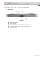
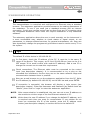
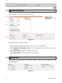
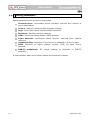
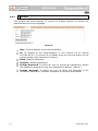
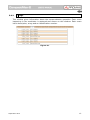
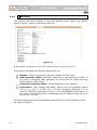
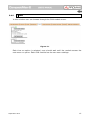
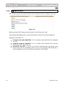
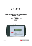
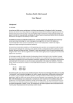
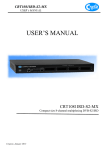
1
CompactMax-2
DVB-S/S2 TO DVB-T2 TRANSMODULATOR
- 0 MI2100 -
SAFETY NOTES
Read the user’s manual before using the equipment, mainly "SAFETY RULES"
paragraph.
on the equipment means "SEE USER’S MANUAL". In this manual
The symbol
may also appear as a Caution or Warning symbol.
WARNING AND CAUTION statements may appear in this manual to avoid injury
hazard or damage to this product or other property.
USER'S MANUAL VERSION
Version
1.0
Date
September 2015
SAFETY REQUIREMENTS
*
The security can be compromised if not applied the instructions in this
manual.
*
Remember that voltages higher than 70 V DC or 33 V AC rms are dangerous.
*
Use this instrument under the specified environmental conditions.
*
The user is not allowed to perform changes inside the equipment. Any change on
the equipment must be done exclusively by specialized staff.
*
Do not obstruct the ventilation system of the equipment.
*
Use appropriate low-level radiation cables for input / output signals, especially on
high level signals.
*
Follow the cleaning instructions described in the Maintenance paragraph.
* Symbols related with safety:
Descriptive Examples of Over-Voltage Categories
Cat I
Low voltage installations isolated from the mains.
Cat II
Portable domestic installations.
Cat III
Fixed domestic installations.
Cat IV
Industrial installations.
TABLE OF CONTENTS
1 INTRODUCTION ........................................................................................ 1
1.1 Description ....................................................................................... 1
2 PACKAGE CONTENT ................................................................................... 3
3 DESCRIPTION AND LOCATION ELEMENTS ................................................. 4
4 ASSEMBLY INSTRUCTIONS........................................................................ 6
4.1 Rack mounting .................................................................................. 6
4.2 Wall Mounting ................................................................................... 6
5 WEBSERVER OPERATION .......................................................................... 7
5.1 Introduction...................................................................................... 7
5.2 Login ............................................................................................... 7
5.3 Screen description ............................................................................. 8
5.4 Status Area ...................................................................................... 8
5.5 Edit options ...................................................................................... 9
5.6 Setting parameters ...........................................................................10
5.6.1 Versions / Store............................................................................11
5.6.2 Control ........................................................................................12
5.6.3 Logs ...........................................................................................13
5.6.4 Receivers.....................................................................................14
5.6.5 CAM............................................................................................15
5.6.6 Input Services ..............................................................................16
5.6.7 Output Services ............................................................................17
5.6.8 LCNs ...........................................................................................18
5.6.9 DVB-T2 modulators .......................................................................19
6 SPECIFICATIONS .....................................................................................20
7 MAINTENANCE .........................................................................................21
7.1 Cleaning Recommendations ...............................................................21
September 2015
DVB-S/S2 TO DVB-T2 TRANSMODULATOR
CompactMax-2
1 INTRODUCTION
1.1
Description
The CompactMax-2 is a compact transmodulation system that allows you to
distribute Satellite TV channels (DVB-S or DVB-S2) in Second Generation Digital
Terrestrial Television (DVB-T2) format.
The CompactMax-2 has 4 satellite inputs. Two inputs are for free channels and
the other two inputs for encrypted channels. There are also two slots to insert a
Card Access Module (CAM) to decrypt these channels and one input for RF
loopthrough.
The CompactMax-2 extracts the sequence of digital data (Transport Stream) of
DVB-S/S2 signal. TS tables are regenerated (PAT, PMTs, SDT and NIT) and PID
remapped. Then signal is modulated again in DVB-T2 format, in order to
distribute it in UHF band. After going through this process, the signal of the
DVB-T2 module can be inserted into a television distribution network. The output
signal has high quality, allowing its way through multiple amplifier stages,
drifters, long cables, etc.
The CompactMax-2 is managed through a webserver via remote control (LAN or
internet) and it is compatible with any standard browser. The webserver is easy
to use and has multiple setting options.
The CompactMax-2 is integrated into a 19” (1U high) rack-mount case, which
fits in any TV head-end installation. It can also be mounted directly on the wall.
Among the practical applications of this transmodulator are:
•
Filter services in order to choose what DVB-S/S2 channels will become
DVB-T2.
•
Restoration of quality in a weak signal.
•
To move DVB-T2 channels from one frequency to other.
•
To change a programme grid without need to retune every TV on the
system.
•
To avoid degradation of signal.
•
To avoid overlapping on other channels.
•
To distribute encrypted programmes as free view in an internal TV
network.
•
To use as a TV repeater to cover shadow areas.
September 2015
1
It can be used in hotels, convention centres, hospitals, ships, emblematic
buildings, mansions, etc.
Figure 1.
September 2015
2 PACKAGE CONTENT
Main Unit.
Quick guide.
Power line.
September 2015
3
3 DESCRIPTION AND LOCATION ELEMENTS
Front view
Figure 2.
1.
Power On indicator.
2.
Error indicator.
3.
Common Interface input (CI#1) for decoder card.
4.
Common Interface input (CI#2) for decoder card.
5.
IP address reset.
September 2015
Rear view
Figure 3.
6.
Not in use.
7.
Ethernet connection for equipment control
192.168.29.30; user: Admin; password: Admin).
8.
Input #4 for satellite signal (DVB-S/S2) free channels.
9.
Input #3 for satellite signal (DVB-S/S2) free channels.
(IP
by
default:
10. Input #2 for satellite
(connected to CI#2).
signal
(DVB-S/S2)
scrambled
channels
11. Input #1 for satellite
(connected to CI#1).
signal
(DVB-S/S2)
scrambled
channels
12. Output for terrestrial RF signal (DVB-T2).
13. RF loopthrough input.
14. Power connector (110 - 230 V AC).
15. Fuse holder.
16. On / Off switch.
17
September 2015
Earth connection.
5
4 ASSEMBLY INSTRUCTIONS
4.1
Rack mounting
Figure 4.
4.2
Wall Mounting
Figure 5.
6
September 2015
5 WEBSERVER OPERATION
5.1
Introduction
The transmodulator is controlled and configured via Ethernet using a standard
browser. The webserver application provides access to the setting parameters of
the modulator. To use it you need just a standard browser and an internet
connection. In this way remote control can be done from any PC computer using
the integrated webserver which does not require installation of any additional
software.
The webserver application allows the user to work remotely on the instrument in
a more comfortable way, whether to check status of signal output, to set
parameters, to change selected services, for general maintenance, etc. User can
also dynamically change the programme grid without need to retune every TV on
the system.
5.2
Login
The default IP of this device is 192.168.29.30.
In first place, check the IP address of the PC. It must be in the same IP
range of the device. This means, an IP like 192.168.29.xxx (xxx can be 0 to
255 except 30 to avoid conflict with module IP address). Add a new IP or
change the current one to meet this requirement.
Check connections. The Ethernet cable must be connected to the control
input (see description chapter). It is recommended to try a ping on the
command-line interface to confirm they are on the same network range and
communication between them is possible.
Now use a web browser to run the webserver application from the PC. Write
the IP address (by default 192.168.29.30) on the URL bar and press ENTER.
If connection is successful, the browser will display a login screen (see
description chapter). Enter the Username and Password (by default both are
“Admin”) then click on ‘Login’ to enter the webserver application.
NOTE: After communication is established, the user can set a new IP address on
the module to suit the range of its own Ethernet network or PC.
NOTE:
Write down the new IP address if you change the default IP address, as it
is required each time you want to communicate. If you neither do not
know nor remember the IP of the module, press the IP address reset
button (see description chapter) to set the device to the default IP.
September 2015
7
5.3
Screen description
After logging, the following screen displays.
Figure 6.
Each screen has 4 specific areas:
Tab area: Each tab access to a specific set of parameters.
Setting Parameters area: Set of parameters according to the tab
selected.
Edit options: Options to edit parameters.
Status area: Transmodulator current state.
5.4
Status Area
The status area shows the current state of input and outputs in the
transmodulator.
Figure 7.
8
September 2015
Receivers: It shows the status (enabled/disabled) for the 4 satellite
receivers. The radio button shows which one is working.
CI modules: It shows the status (initialized/no card) for the CAM module
inserted in the common interface (CI) slot. It also shows the satellite
receiver selected and the number of selected services for each card. The
radio button shows which one is working and its status (green (ok) / red
(error).
DVB-T2 modulators: It shows the status of the RF output (RF muted/…),
output frequency and signal source. The radio button shows which one is
working.
5.5
Edit options
Edit options are:
Refresh: It reloads
transmodulator.
data
on
the
webserver
application from the
Modify: It applies changes made on the transmodulator.
Expand: It expands the data tree.
Collapse: It collapses the data tree.
September 2015
9
5.6
Setting parameters
Setting parameters are grouped in these tabs:
Versions/store: Information about firmware versions and options to
store/reset/reboot.
Control: Network, password and language settings.
Logs: Information about transmodulator operation.
Receivers: Satellite receivers settings.
CAM: Conditional Access Module (CAM) settings.
Input Services: Information about services captured from satellite
receivers.
Output Services: Selection of services to be released on the RF output.
LCNs: Selection of logical channel number (LCN) for each service
selected.
DVB-T2 modulators: RF output settings to distribute in DVB-T2
standard.
In next chapters each one of these options are explained in detail.
10
September 2015
5.6.1
Versions / Store
This window gives
store/reset/reboot.
information
about
firmware
versions
and
options
to
Figure 8.
Versions area: It shows information about firmware versions for different
components of the transmodulator.
Internal IDs area: It shows information about the identification number
of the equipment and name.
Store fields button: It applies and saves all changes made in the
webserver on the transmodulator.
Reboot button: It reboots the transmodulator.
Reset to factory defaults button: It recovers and applies factory
settings on the transmodulator.
Download stored configuration: It downloads current configuration as
a file, from transmodulator to PC.
Upload and store configuration file: It uploads and stores the
configuration file selected by the user, from PC to transmodulator.
September 2015
11
5.6.2
Control
This window has some settings to connect to a data network, to change the
password and the menu language.
Figure 9.
MAC: Physical address of the transmodulator.
IP: IP address of the transmodulator in the network (IP by default
192.168.29.30). To recover IP by default press the physical button on the
transmodulator (see description chapter).
Mask: Network parameter.
Gateway: Network parameter.
Change password: It allows the user to change the password to access
the webserver application (user and password by default: “Admin”).
Change language: It allows the user to select the language of the
webserver application. Available languages are English and Spanish.
12
September 2015
5.6.3
Logs
This window gives information about the transmodulator operation. Each event
happening in the modulator is captured and shown on this window. Each event
has a description, a tag and an identification number.
Figure 10.
September 2015
13
5.6.4
Receivers
This window has some settings to tune the satellite signal. When the satellite
signal is locked, it shows information about it.
Figure 11.
In first place, select one or two SAT inputs (from 1 to 4) to work on.
Then expand the data tree. Setting parameters are:
Disable: Check or uncheck to enable / disable the SAT input.
LNB frequency (MHz): Oscillator frequency of the antenna (in MHz). If
you have a Universal LNB, generally are 9750 MHz for LOW band and
10600 MHz for HIGH band.
Downlink frequency (MHz): Tuning frequency of the satellite.
Polarization: LNB voltage and band. Select from the available values
(13 V, 18 V, 13 V + 22 kHz, 18 V + 22 kHz, External). Generally 13 V is
used for VERTICAL polarization and 18 V for HORIZONTAL polarization. If
you want to tune frequencies corresponding to the satellite high band you
should use +22 kHz.
The rest of parameters are automatically detected by the transmodulator when
the signal is locked.
14
September 2015
5.6.5
CAM
In this window user can browse through the CAM module menu.
Figure 12.
Each time an option is selected, user should wait until the module access the
next menu or option. Each CAM module has its own menu settings.
September 2015
15
5.6.6
Input Services
This window gives information about services captured from satellite receivers.
Figure 13
Select the same SAT inputs than selected in the “Receivers” tab.
Then expand the data tree to check information about the services captured.
Available information is:
Transport stream identifier: It is a number that identifies the transport
stream.
Original network identifier: It is a number that identifies the network
from where the signal comes.
Received services: It shows all services detected and its tables. Each
table shows all the metadata carried in the corresponding PSI/SI tables in
a tree diagram so user can deploy its content to the detail.
16
September 2015
5.6.7
Output Services
This window gives information about services to be released on the RF output.
Figure 13.
Select the RF output (RF 1 or 2) to work on.
Then expand the data tree to set the parameters in order to release services at
the output:
LCNs Network identifier: It is the number that identifies the network
where the signal is distributed.
Network name: It is the name that identifies the network where the
signal is distributed.
Transport stream identifier: It is a number that identifies a specific
transport stream.
Original network identifier: It is a number that identifies the network
from where the signal comes.
Private data specifier: Data that the receiver uses to properly identify
the LCN value.
Input: Select the SAT input (from 1 to 4) to select services.
Generated services: It shows services generated from the selected
transport stream. User can select services by clicking on “Change
selection” button.
If the user wants to use the same network identifier, network name or private
data specifier on all outputs, use the external box and click on “Use for all
outputs” box.
September 2015
17
5.6.8
LCNs
This window allows user to select the logical channel number (LCN) for each
service selected.
Figure 14.
LCN: Logical channel number is the number that specifies the index to
sort services on the digital terrestrial television receiver.
There is also one option to auto number all services by filling the “First LCN” box
and clicking on “Auto number”.
18
September 2015
5.6.9
DVB-T2 modulators
This window shows RF output settings in order to distribute services in DVB-T2
format.
Figure 15
Select the same RF outputs than selected in the “Output services” tab.
Then expand the data tree to set the parameters in order to release services at
the output.
September 2015
19
6 SPECIFICATIONS
Specifications
CompactMax-2
SATELLITE INPUTS
4 satellite inputs
LNB
Typical LO frequencies
Supply
22 kHz signalling
Indicators
IF frequency range
Input power range
Input Impedance
Input return loss
Noise figure
DVB-S
DVB-S2
DVB-T2 OUTPUTS
Carrier frequency
Output level
Output attenuation
MER
Channel bandwidth
FFT size
Guard Interval
Pilot pattern
Number of PLPs
Constellation
FEC
9750 MHz, 10600 MHz
External/+13 (vert.pol.)/+18V (hor.pol.), 5 W each satellite input (max.)
Low/high frequency band
Over/under load/current and malfunction
950 MHz to 2150 MHz (LNB LO freq ±downlink freq)
-70 to –20 dBm typ., -50 dBm nominal, -5 dBm max
75 Ω
> 10 dB
14 dB maximum
Up to 62 Msymb/s
Up to 45 Msymb/s
2 DVB-T2 outputs
47 MHz to 858 MHz in 1 kHz steps
-20 dBm ± 1 dB, 50 ohms
0 to 30 dB in 0.1 dB steps
38 dB minimum, >40 dB typical
8, 7, 6, 5 MHz with selectable spectral inversion 2k only
2k only
1/32, 1/16, 1/8, 1/4, 1/128, 19/128, 19/256
PP1-PP8
1
QPSK, 16QAM, 64QAM, 256QAM (rotated or not)
Short, Normal; rates 1/2, 3/5, 2/3, 3/4, 4/5, 5/6
CONDITIONAL ACCES
Two Common Interface DVB-CI compliant slots
TS PROCESSING
Selection of arbitrary number of services from the received TS (bit rate of
the input services selected < DVB-T2 output bit rate)
NULL packet deletion and PCR restamping
Regeneration of the PAT, PMT, SDT, NIT tables
User-defined NID, ONID, Network Name, LCNs with associated private data
specifier, Service Name, Provider Name and TS ID
REMOTE CONTROL
1000 Mbps Ethernet connector to access a webserver
User-defined IP address
OPERATING
TEMPERATURE
From 0 to 45 ºC
NOTE: Equipment specifications are set in these environmental operating conditions. Operation outside these
specifications are also possible. Please check with us if you have specific requirements.
Packing Recommendations
You should retain all packaging materials on a permanent basis if necessary to return the equipment to the
Technical Assistance Service.
20
September 2015
7 MAINTENANCE
7.1
Cleaning Recommendations
CAUTION:
To clean the cover, take care the instrument is disconnected.
CAUTION:
Do not use scented hydrocarbons or chlorized solvents. The
cover should be cleaned by means of a light solution of
detergent and water applied with a soft cloth. Dry thoroughly
before using the system again.
CAUTION:
Do not use for the cleaning alcohol or its derivatives, these
products can attack the mechanical properties of the materials
and diminish their useful time of life.
September 2015
21
PROMAX ELECTRONICA, S. L.
Francesc Moragas, 71-75
08907 L’HOSPITALET DE LLOBREGAT (Barcelona)
SPAIN
Tel. : 93 184 77 00 * Tel. Intl. : (+34) 93 184 77 02
Fax : 93 338 11 26 * Fax Intl. : (+34) 93 338 11 26
http://www.promaxelectronics.com
e-mail: [email protected]