1
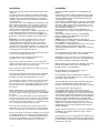
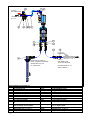
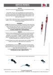
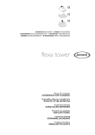
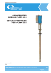
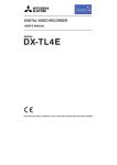
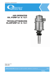
AIR OPERATED OIL PUMP 2:1
LUFTDRIVEN OLJEPUMP 2:1
USER MANUAL
BRUKSANVISNING
22780
22780 Rev. 1c 090317 leka
1(8)
General
Allmänt
The air operated pump has two main parts. One double
acting air motor driving a true double acting liquid pump.
The fluid is sucked into the pump through the intake valves
both when the piston is on the upward and downward
stroke. That intake is marked with IN The fluid is also
discharged in both up- and downs strokes through the
outlet body and it is marked with OUT.
The relationship between then area of the air piston and
area of the pump decides the pressure ratio. The pressure
ratio is 2:1 and the theoretical pressure when the pump has
stopped is ~2 times higher than the air pressure.
The exhaust air is blown out through a silencer made of
sintered brass.
Important! This pump model has a “divorced” air motor
and will often be mounted in horizontal position. That
means an air lubricator MUST be connected between the
air supply and the pump motor.
Safety precautions
The pump is intend to be used with petroleum based fluids
like oil, pure glycol and diesel fuel.
The pump may not be use for pumping petrol or other
hazardous or explosive fluids. It is not suitable for water or
acid.
Check that all accessories and components are suitable for
the distributed fluid and the working pressure of the system.
Do not use higher air pressure than necessary to reach
suitable system pressure.
Do not exceed the maximum air pressure of the pump, 1.0
MPa (10 Bar). Normal air pressure is between 0.5-0.6 MPa
(5-6 Bar)
The system must be tested to 1.3 times the working
pressure before being put into operation.
Close and disconnect the air supply and relieve the liquid
pressure in the system before any work to the pump or
system is carried out
Only use genuine manufacturers spare parts. Never use
worn or damaged spare parts.
Always turn off the air pressure to the pump when the
premises are unattended.
Technical data
Den tryckluftsdrivna pumpen har två huvuddelar, en
dubbelverkande kolvmotor och en dubbelverkande
vätskedel.
Vätskan sugs in i pumpdelen genom den
bottenventilen som är märkt med IN och som i
normalfallet är placerad på vänster sida. Vätskan
trycks ut genom den nedre högra anslutningsdelen
som är märkt med OUT, både vid upp- och
nedåtgående rörelse.
Förhållandet mellan luftkolvens area och pumpkolvens
area anger tryckförstärkningen. Tryckförstärkningen är
2:1 och det teoretiska trycket blir, när pumpen stannat,
~2 gånger högre än det ingående lufttrycket.
Returluften blåses ut och ljuddämpas via en sintrad
ljuddämpare.
Viktigt! Då denna pumpmodell ofta monteras liggande
och dessutom har sk. delad luftmotor MÅSTE man
ansluta en luftsmörjare mellan luftanslutningen och
pumpmotorn.
Produktsäkerhetsanvisningar
Pumpen är avsedd för pumpning av smörjande och
petroleumbaserade vätskor som olja, ren glykol och
diesel. Pumpen får inte användas för pumpning av
bensin eller andra explosiva vätskor. Den är inte heller
lämplig för syror eller vatten.
Kontrollera att alla anslutna komponenter är avsedda
för den pumpade vätskan och lämpade för systemets
arbetstryck.
Använd inte högre lufttryck än nödvändigt för att uppnå
lämplig systemfunktion.
Överstig aldrig max. trycket 1,0 Mpa (10 Bar). Normalt
arbetstryck är mellan 0,5 – 0,6 Mpa (5-6 Bar.
Provtryck alla rörledningar med 1.3 x systemets
arbetstryck innan det tas i drift.
Stäng av eller koppla bort trycklufttillförseln och avlasta
systemet innan något arbete på pump eller system
påbörjas.
Använd eller återmontera aldrig en sliten eller skadad
detalj.
Stäng alltid av eller koppla bort tryckluften till pumpen
över natten och vid driftsuppehåll.
Tekniska data
Pressure ratio
2:1
Tryckförhållande
2:1
Total length
662 mm / 26 1/16”
Totallängd
662 mm
Pump tube length
265 mm / 10 7/16”
Pumprörslängd
265 mm
Pump tube diameter
Ø 65 mm / 2 9/16”
Pumprörsdiameter
Ø 65 mm
Air motor diameter
Ø 80 mm / 3 9/16”
Luftmotordiameter
Ø 80 mm
Stroke length
Approx. 100mm /4”
Slaglängd
ca 100mm
Weight
10.0 kg / 22,05 lbs
Vikt
10,0 kg
Max. air pressure
1 Mpa / 1450 psi
Max. lufttryck
1 Mpa, 10 Bar
Min. air pressure
0.4 Mpa/ 58 psi
Min. lufttryck
0.4 Mpa, 4 bar
Max. fluid pressure
2.0 Mpa/ 290 psi
Max. vätsketryck
2.0 Mpa, 20 bar
Burst pressure
Min. 10.0 Mpa/ 1450
psi
Sprängtryck
Min. 10.0 Mpa
Free delivery
Approx. 60 l/min/
Fritt avgivet vätskeflöde
ca. 60 l/min
Recommended max. delivery
Approx. 40 l/min
Rekommenderat max. flöde
ca. 40 l/min
Air connection
BSP ¼” female/ G ¼”
Luftanslutning
G ¼” inv.
Fluid outlet
BSP ¾” female/ G ¾”
Vätskeutlopp
G ¾” inv.
Fluid inlet
BSP ¾” female/ G ¾”
Vätskeinlopp
G ¾” inv.
Noice level at 0.7 Mpa/100 psi
84 dBa
Ljudnivå vid 0.7 Mpa
lufttryck
84 dBa
(Engine oil SAE 30 at 7 Mpa/100 psi air pressure and 20°C/68 °F)
2(8)
(Motorolja SAE 30 vid 0.7 Mpa lufttryck och 20 °C)
Installation
Installation
Remove the protective plugs in the air inlet and the fluid in
and outlet.
The pump can be placed either in vertically or horizontal
position. Make shore that the wall or bracket has strength
enough to carry the pump weight and can carry out the
vibrations and movement force which will be created from
normal operation.
Connect the suction hose to (IN) on the pump(G¾”f). If the
fluid is delivered in a 200 l’s drum a separate suction rise
tube shall be installed. Place the suction tube with 10-15
mm space over the drum bottom and lock it by the drum
adapter which is included drum adapter.
If the fluid is in a storage tank a separate closing valve has
to be installed between the tank and the suction hose.
Connect the liquid outlet hose into the outlet (OUT) of the
pump (G ¾" f). Mount the air nipple into the air inlet (G ¼"
f).
Important! The pump is not allowed to be connected
directly against an air supply pipe. It has to be an air
regulator with gauge into the air line prior to the pump.
A lubricator must be installed in the line between the air
connection the pump and the air piping. Use always an air
lubricator oil of good quality. Adjust the oil consumption to
one drop/min at normal operation speed
Tag bort allt skyddsemballage och skyddspluggar från
pumpen.
Pumpen kan monteras antingen horisontellt eller vertikalt.
Se till att väggen och eventuellt pumpfäste är tillräckligt
starkt för att bära pumpens vikt och att de tål de krafter
som uppkommer vid drift.
Anslut sugslangen till IN på pumpen (G¾”inv.). Om vätskan
kommer i ett fat skall en separat sugutrustning med sugrör
användas. Ställ in sugrörets nivå så att det blir ca 10-15
mm spel mot fatets botten och lås därefter fast röret med
den medföljande fatadaptern.
Om vätskan finns i en tank skall det alltid finnas en
avstängningsventil som gör det möjligt att stänga inloppet
till pumpen.
Anslut utloppsslangen mot pumpens utlopp (OUT)
(G¾"inv.). Montera luftsnabbkopplingen i pumpens
luftanslutningshål (G1/4" inv.).
Viktigt! Pumpen får aldrig kopplas in direkt mot en
tryckluftledning. Det skall finnas ett luftbehandlingsaggregat
med möjlighet att reglera lufttrycket.
Det skall finnas en luftsmörjare monterad och denna skall
alltid vara fylld med en luftverktygsolja. Ställ in
smörjmedelsförbrukningen till ca 1 droppe/min vid normal
drift av pumpen.
A shut-off valve should always be installed into the air line
before the air regulator and lubricator.
En avstängningsventil ska alltid monteras på uttagsstället
för tryckluft. Den monteras före ev. filter/regulator.
The pipe work must be installed according to local
regulations for this type of equipment.
Rörledningssystemet ska utföras med iakttagande av de
rörledningsbestämmelser och normer som myndigheterna
har beslutat ska gälla för denna typ av utrustning.
Do not mount a pump directly onto a sheet metal wall or
similar construction, which can create noise resonance and
augment the normal noise level of the pump.
A hose must be mounted between the outlet of the pump
and the fixed pipe work..
A shut-off valve must always be installed at the beginning
of the pipe work to make service easier and to make it
possible to cut off the flow of liquid when necessary.
At each branch and before each hose reel outlet a shut-off
valve should be installed. It is also advisable to fit an oil
filter. The shut off valve and oil filter should have the same
pressure rating as the corresponding working pressure of
the system.
When starting up the system for the first time, all valves
and meters should be opened to bleed air from the system.
If air gets compressed in the pipe work, this could damage
the meters.
It may be necessary to bleed the system at a high point to
release any air pockets. These air pockets can be difficult
to remove, but they have to be removed so that the meters
and solenoid valves work correctly. In a monitored system
it is essential to bleed all air from the system.
If there are filters mounted in the system to take care of
dirt, it will be necessary to clean out these filters from time
to time, especially after a new system has been installed.
Do not let the pump run fast when starting up a new system
or changing barrels in an existing system. Start the pump
by lowering the air pressure on initial priming and increase
the air pressure gradually as the system is primed. In a
new system always check that there are no oil leaks.
3(8)
Montera aldrig en pump direkt på en plåtvägg, eller annan
liknande konstruktion som kan ge resonansljud och
förstärka pumpens normala ljudnivå.
En slangledning ska monteras mellan pumpens
utloppsanslutning och rörledningen.
En avstängningsventil ska alltid monteras i början av
rörledningen för att underlätta vid service och för möjlighet
att stänga av flödet vid behov.
Vid varje förgrening och före varje slangrulle/uttagsställe
ska en avstängningsventil monteras. Den ska ha en
tryckklass som motsvarar maximalt arbetstryck i systemet.
Vid första uppstart ska alla mätverk och
avstängningsventiler öppnas för att låta den annars
innestängda luften komma ut. Om man komprimerar luft i
rörledningen och sedan öppnar en ventil eller ett mätverk
kan det uppstå skador både på mätverk och på den person
som eventuellt befinner sig framför munstycksöppningen.
Ibland kan det bli nödvändigt att lossa på någon högt
belägen koppling eller skarv för att få bort luftfickor. Dessa
luftfickor kan vara svåra att bli av med och de måste
avlägsnas för att mätverk, magnetventiler och eventuella
övervakningssystem ska kunna arbeta på rätt sätt utan
onödiga störningar.
De filter som finns installerade i systemet ska regelbundet
kontrolleras och rengöras. Filterinsatsen bytes om det
anses nödvändigt.
Låt inte pumpen "rusa" under uppstart eller vid byte av fat
när rörledningen återfylls. Sänk farten på pumpen genom
att sänka lufttrycket. Kontrollera under uppfyllning att inget
läckage finns i systemet.
¼"BSP (f)
AIR CONNECTION
LUFTANSLUTNING
G¼" inv.
DRUM ADAPTER 2"BSP (m)
DRUM SUCTION ATTACHMENTS
SUGRÖR FÖR 200L's FAT
G2" FATADAPTER
Drum installation/ Installation fat
Pos
Description
1
Air treatment unit
2
Wall bracket included into 42103
3
Adapter, ¼”-¼”BSP tapered
4
Air line lubricator
5
Rubber steel washer, GBR¼”
6
Air connection hose, ¼”-1.5 m
7
Quick coupling
8
Air connection nipple
9
Drum Suction Attachment, Tube 1.08
m
10
2 pcs Adapter, ¾”-1” BSP, One is incl.
into 28310 and one into 28079
11
2 pcs Rubber steel washer, GBR ¾”
12
Dispensing hose, 1.5 m x ¾
13
Adapter 1”-1” BSP, incl into 28079
4(8)
1"BSP (f)
PIPE CONNECTION
VALVE NOT INCLUDED
RÖRANSLUTNING G1" inv.
VENTIL INGÅR EJ
Product nr
42103
(42110)
301296
42108
10103529
48001
44516
48501
28310
Beskrivning
Luftbehandlingsenhet
Väggfäste ingår i 42103
Anslutningsnippel, R¼”-R¼”
Luftsmörjare
Gummi-stålbricka, GBR ¼”
Luftanslutningsslang, ¼”-1,5 m
Snabbkoppling
Luftanslutningsnippel
Sugslangsats med sugrör 1,08 m
(25102065)
2 st Mellanstycke, G¾”-G1”, En ingår i 28310
och en ingår i 28078
2 st Gummi-stålbricka, GBR ¾”
Utloppsslang, 1,5 m x ¾”
Adapter G1”-1”, ingår I 28079
10103526
28079
(25102011)
1"BSP (f)
PIPE CONNECTION
VALVE NOT INCLUDED
RÖRANSLUTNING G1" inv.
VENTIL INGÅR EJ
¼"BSP (f)
AIR CONNECTION
LUFTANSLUTNING
G¼" inv.
1"BSP (f)
TANK CONNECTION
TANKANSLUTNING
G1" inv.
Installation tank
Pos
Description
1
Air treatment unit
2
Wall bracket included into 42103
3
Adapter, ¼”-¼”BSP tapered
4
Air line lubricator
5
Rubber steel washer, GBR¼”
6
Air connection hose, ¼”-1.5 m
7
Quick coupling
8
Air connection nipple
9
3 pcs Rubber steel washer, GBR 1”
10
Adapter,1” BSP
11
Valve 1”BSP
12
Suction hose, 1.0 m x 1”, incl. one
adaptor 1”-1”BSP
13
Adapter ¾”-1” BSP
14
2 pcs Rubber steel washer, GBR ¾”
15
Dispensing hose 1.5 m x¾”, incl. two
adaptors, one ¾”-1” BSP and one 1”1” BSP
5(8)
Product nr
42103
(42110)
301296
42108
10103529
48001
44516
48501
10103517
25102011
30101081
28080
25102011
10103526
28079
Beskrivning
Luftbehandlingsenhet
Väggfäste ingår i 42103
Anslutningsnippel, R¼”-R¼”
Luftsmörjare
Gummi-stålbricka, GBR ¼”
Luftanslutningsslang, ¼”-1,5 m
Snabbkoppling
Luftanslutningsnippel
3 st Gummi-stålbricka, GBR1¾”
Mellanstycke, G1
Avstängningsventil G1”
Sugslang, 1,0 m x 1”. Det ingår en adapter
G1”-G1”
Adapter G¾”-1”
2 st Gummi-stålbricka, GBR ¾”
Utloppsslang 1,5 m x ¾. Det ingår två
adaptrar; en G¾”-G1” och en G1”-G1”
Maintenance
For your personal safety disconnect the air motor from the
air line and relieve the fluid system pressure before any
service is undertaken.
Check the following regularly:
Empty the clean out the air filter depending of dirt and
condensate water..
The lubricator must always be filled with air tool oil or
similar.
Mineral based motor oil, SAE 10, can also be used.
Synthetic oil or other oils must not be used.
Check there isn’t any leakage in the connections and
couplers.
Check all connected hoses for wear or possible damage.
Keep the lubricant and the equipment clean and free from
dirt and other waste collecting materials.
All dirt or foreign parts entering the drum can be pumped out
into the pipe lines and later destroy pumps or meters or
even worse destroy an engine or gear box.
When changing drums it is especially important that the
suction tube bottom valve are kept off the floor and free from
dirt. The dirt will otherwise enter the pump and contaminate
the oil and possibly damage it. Put the suction tube into a
clean drum or rest it on a bracket while changing the drum.
Have a spillage container available when unloading or
uncoupling the pipe work.
Re-check all the connections in the system for leakage after
the first 6-8 hours of operation and later each 6 month.
Do not over tight the swaged couplings.
6(8)
Underhåll
Vid allt arbete på utrustningen skall tryckluften alltid stängas av
med ventilen eller genom att snabbkopplingen kopplas bort.
Därefter skall rörledningen avlastas från allt vätsketryck.
Töm och gör rent i luftfilter med avseende på kondenserat
vatten och försmutsning.
Luftsmörjaren skall alltid hållas fylld med luftverktygsolja eller
motsvarande
Vanlig petroleumbaserad motorolja, SAE 10, går också bra.
Syntetisk motorolja eller andra oljor får EJ användas.
Kontrollera att det inte finns någon form av läckage i
anslutningar eller kopplingar.
Titta och känn på alla anslutna slangledningar och kontrollera
dem med avseende på slitage och eventuella skador.
Håll alltid uppställningsplatsen och utrustningen ren och fri från
spån eller andra oljespilluppsamlingsmaterial.
Allt smuts och liknande som kommer ned i fatet, kommer att
pumpas ut i rörledningssystemet.
Vid byte av fat är det särskilt viktigt att det inte fastnar smuts
eller andra föroreningar på sugröret.
Smutsen följer med ned i fatet och förorenar oljan. Se till att det
finns någon form av kärl, (väl rengjort) eller
upphängningsanordning att placera sugröret i vid bytet.
Ha ett uppsamlingskärl till hands vid avlastning eller
bortkoppling av rörledning.
Kontrollera alla anslutningar efter 6-8 timmars drift och sedan
var 6:e mån
Överdra inte rörkopplingarna.
Spare part kit
Reservdelssats
Packing kit for pump 2:1:
242 64 02
Content 22 Packings and O-rings
Other parts will be ordered by Pos nr and with
mention of pump model with serial nr.
Packningssats för 2:1 pump:
242 64 02
Innehåller 22 packningar och o-ringar
Andra delar beställs med hjälp av Posnr och
angivande av pumpens modell och serie nr.
Conformity Declaration for Machinery /
Alentec & Orion AB, located in Saltsjö-Boo, Sweden,
declares by the present certificate that the mentioned
machinery is in conformity with the following standards or
other normative documents (DIN 24558/10.91, Din EN
292/2/11.91) and has been declared in conformity with
the EC Directive 89/39/EEC.
Konformitetsdeklaration för Maskiner
Alentec & Orion AB, med hemvist i Saltsjö-Boo, Sverige,
deklarerar genom detta certifikat att den omnämnda
utrustningen är tillverkad efter följande standards (DIN
24558/10.91, Din EN 292/2/11.91) och deklareras i
enlighet med EC Direktiv 89/39/EEC
Saltsjö-Boo 2008-10-06
Anders Bertlid
Managing Director
7(8)
Michael Theorin
Technical Director
MPa
M ax . Pr essure
12750
0808-0000
60:1 1.0
Mo del No
Ra tio
8(8)
Ser ie No
Alentec & Orion AB,
Box 108,
SE-132 23 Saltsjö-Boo
Tel: +46 8 747 67 00
Fax: +46 8-715 20 74
e-mail: [email protected]
www.alentec.se.