1
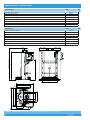
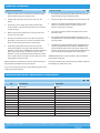
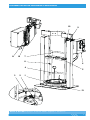
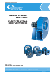
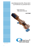
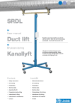
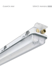
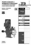
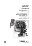
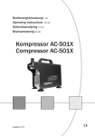
USER MANUAL / BRUKSANVISNING
TWO POST RAM
TVÅPELARLYFT
Part No. / Art. Nr. / Réf.:
18300, 18310, 18320
Alentec & Orion AB Grustagsvägen 4, SE-13840, Älta, SWEDEN · [email protected] · www.alentec.com
105036
1
TECHNICAL DATA / TEKNISKA DATA
18300
TECHNICAL DATA
Pneumatic cylinder diameter
Pneumatic cylinder stroke
Equipment minimum height
Equipment maximum height
Base dimensions
Air inlet thread
Maximum air pressure
Weight (without pump)
80 mm
1000 mm
1320 mm
2230 mm
830 x 600 mm
1/2" BSP (F)
10 bar (140 psi)
183 kg
18300
TEKNISKA DATA
80 mm
1000 mm
1320 mm
2230 mm
830 x 600 mm
1/2" BSP (F)
10 bar (140 psi)
183 kg
830
1156
LOWERED 1320 / RAISED 2230
Diameter pneumatisk cylinder
Slaglängd pneumatisk cylinder
Utrustningens min höjd
Utrustningens maxhöjd
Storlek basplatta
Luftanslutning
Max lufttryck
Vikt (utan pump)
620
720
600
Ø
554
355
455
830
980
771
12
106,5
300
Alentec & Orion AB Grustagsvägen 4, SE-13840, Älta, SWEDEN · [email protected] · www.alentec.com
2
EN
SE
GENERAL / ALLMÄNT
OPERATION
/ ANVÄNDNING
/ GÉNÉRALITÉS
GENERAL
EN
Fixed two post ram for the supply of grease, inks, etc. Operated by
compressed air. This unit uses two pneumatic cylinders connected with a
metal structure fixed to a reinforced base plate, resulting in a very robust
piece of equipment that is very small for the type of drums with which it can
work.
This unit was designed to supply grease with the greater guarantee of
priming of the pump, and maximum use of the grease drums. It incorporates
a robust aluminium follower plate, which has a sealing system made up of
lip seals or double O-rings. This system guarantees the walls of the drum
are clean and that it is perfectly sealed, which stops impurities getting in or
simply protects from the weather. The model and material of the lip or seal
used depends on its compatibility with the substance pumped. There are
also different pump kits designed to optimise the work depending on the use
required of this unit.
When the unit is correctly secured, the plate can be raised together with the
pump to a given height to facilitate changing the used drum. This unit has a
control cabinet for the ram and for the pump installed in the unit.
ALLMÄNT
SE
Fast monterad pumplyft för pumpning av fett, färg osv. Drivs av
tryckluft. Enheten använder två pneumatiska cylindrar som sitter i en
metallkonstruktion på en förstärkt basplatta vilket innebär att enheten är
mycket robust och kompakt för denna typ av utrustning.
Denna enhet är avsett för pumpning av fett med mindre risk att luft kommer
in i systemet och maximalt utnyttjande av fettfatet. Enheten innehåller ett
robust gjutet följelock i aluminium, som har ett tätningssystem som består av
läpptätningar eller dubbla O-ringar. Detta system garanterar att väggarna i
fatet är rena och att det är helt tätt, som förhindrar att föroreningar kommer
ner i fettet eller bara skyddar mot väder och vind. Typen av tätningssystem
beror på dess förenlighet med mediet som skall pumpas. Det finns också
olika pumpsatser, beroende på vilken applikation som enheten skall
användas till.
När enheten är monterad på plats så kan följelocket och pumpen höjas upp
för att underlätta bytet av fat. Enheten har en samlad kontrollpanel för både
pumplyften och själva pumpen som sitter i enheten.
PRODUKTSÄKERHETSANVISNINGAR
SAFETY PRECAUTIONS
Read all instruction manuals, tags, and labels before operating the
equipment.
This equipment is for professional use only.
Do not alter or modify this equipment. Use genuine components provided
from Alentec & Orion AB.
Non compatible fluids may cause damage in the pump and serious personal
injury.
The pump generates high or very high pressures. Do not exceed the
maximum air inlet pressure of 10 bar.
Do not exceed the drum’s pressure limits. Be sure of the drum’s pressure
limitations and regulate the pressure within the safety limits when supplying
air to the follower plate. Do not try to use the unit until you have taken all
possible precautions to guarantee that the unit has been installed correctly
and that the base has been firmly secured to the concrete floor.
Avoid electrical discharges. Ensure there are no electrical cables, devices or
accessories above the hoist. Examine the work area and take the measures
necessary to ensure that enough space is maintained for the installation of
the hoist and for the pump to be lifted as much as possible.
Maintain a minimum safety distance when raising and lowering the ram. Do
not get too close; operate it from a safe place, so you cannot get trapped
between the unit and its mobile elements.
Take care when inserting the follower plate into the drum. When not in use,
be sure to shut off the air supply to avoid accidents.
Läs alla instruktioner, typskyltar och etiketter innan användning av
utrustningen.
Denna utrustning är endast avsedd för yrkesmässigt bruk.
Bygg ej om eller modifera denna enhet. Använd enbart reservdelar som
erhålls av Alentec & Orion AB.
Att pumpa icke kompatibla väskor med pumpen kan orsaka skador i
pumpen eller allvarliga personskador.
Pumpen skapar väldigt högt tryck. Överskrid aldrig max lufttryck 10 bar.
Försök inte att använda enheten tills du har åtgärdat alla möjliga åtgärder
för att garantera att enheten har installerats på rätt sätt och att basen har
monterats stadigt i golvet.
Undvik elektriska stötar. Se till att det inte finns några elektriska kablar,
apparater eller tillbehör ovanför pumplyften. Undersök arbetsområdet och
vidta nödvändiga åtgärder för att se till att det finns tillräckligt utrymme för
installation av lyften och för att pumpen ska kunna lyftas till maxhöjd.
Håll ett säkerhetsavstånd när höjning och sänkning av pumpen sker. Stå ej
för nära; använd den från en säker plats, så att du inte kan fastna mellan
enheten och dess rörliga delar.
Var försiktig när du sänker ned följelocket i fatet. När den inte används, se
till att stänga av lufttillförseln för att undvika olyckor.
Kontrollera att alla operatörer som arbetar med den här enheten har
utbildats i säkra arbetsrutiner, att de förstår sina begränsningar och
använder skyddsutrustning när så krävs.
Check that all the operators that work with this unit have been trained in
safe working practices, that they understand their limitations and use safety
equipment when required.
Alentec & Orion AB Grustagsvägen 4, SE-13840, Älta, SWEDEN · [email protected] · www.alentec.com
3
INSTALLATION / INSTALLATION
EN
GENERAL
SE
ALLMÄNT
This unit comes completely assembled, apart from the following details for
proper installation and commissioning.
Denna enhet levereras färdigmonterad, bortsett från följande detaljer för
installation och driftsättning.
The unit is supplied with the control cabinet in the transport position. To
place the control panel in the working position, simply disconnect pipes A
and B from the control panel (see Fig. 5) and remove the pin from the hole
locking the control panel (see upper arrows) and lower the control panel into
its new working position (see arrow for rotational direction). Once the control
panel is in place, insert the pin. Then connect the pipes in the lower part of
the control panel according to the diagram (see Fig. 5).
Enheten levereras med kontrollpanelen i transportläge. För att placera
kontrollpanelen i driftläge, koppla bort slang A och B från kontrollpanelen
(se fig. 5) och ta bort låspinnen från hålet som låser kontrollpanelen i
dess läge (se övre pilar) och vrid kontrollpanelen i sin driftläge (se pil för
rotationsriktningen). När kontrollpanelen är på plats, sätt tillbaka stiftet.
Anslut sedan slangarna till kontrollpanelen enligt diagrammet (se fig. 5).
To facilitate its handling, the unit is supplied with a pallet system integrated
in the design. This system is composed of two galvanised sheet metal
profiles bolted to the base plate. Once you have selected where you will
secure the unit, it is necessary to remove these profiles.
Pay special attention to the work area that will be above the ram; this work
area shall be free of objects and any electrical devices. Once you have
finished the above step, secure the unit definitively to the floor.
Connect pipes A and B to the pneumatic control panel according to the
details in the drawing. Connect it to a compressed air inlet with a maximum
pressure of 10 bar and check that all the accessories of the pneumatic
system are in good condition after transport.
To extend the life of the unit and the pump, use a filter at the control panel
input.
Transport position /
Transportläge
För att underlätta dess hantering är enheten flyttbar med gaffeltruck.
Detta system består av två galvaniserade plåtprofiler som är skruvade
i basplattan. När enheten skall installeras på plats är det nödvändigt att
avlägsna dessa profiler.
Kontrollera arbetsområdet som kommer att vara över pumplyften; detta
område ska vara fritt från föremål och eventuella elektriska apparater.
Enheten skall bultas fast i golvet.
Anslut rör A och B till den pneumatiska manöverpanelen enligt uppgifterna
på ritningen. Anslut tryckluften med ett maximalt tryck på 10 bar och
kontrollera att alla tillbehör i det pneumatiska systemet är i gott skick efter
transporten.
För att förlänga livslängden på enheten och pumpen montera ett filter före
kontrollpanelen.
Working position /
Driftläge
Fig 5
Alentec & Orion AB Grustagsvägen 4, SE-13840, Älta, SWEDEN · [email protected] · www.alentec.com
4
GENERAL / ALLMÄNT
OPERATION
/ ANVÄNDNING
/ GÉNÉRALITÉS
TO RAISE THE RAM FOR THE FIRST TIME
EN
ATT LYFTA FÖR FÖRSTA GÅNGEN
SE
1.
Ensure there is nothing above the hoist. In addition, read the SAFETY
PRECAUTIONS on page 2.
1.
Säkerställ att området ovanför pumplyften är fritt. Läs även
SÄKERHETSANVISNINGAR på sid 2.
2.
Move the control cabinet lever to the “UP” position. Do not touch any
part of the unit while it is moving!
2.
Dra reglaget för höjdreglering till läge UPPÅT. Rör ingen del av
enheten medans den rör sig!
3.
Lift the follower plate higher than the top of the drum. Stop the
hoist ascending further by moving the control cabinet lever to the
“NEUTRAL” position (centre).
3.
Lyft enheten tills den går fritt från fatet. Stanna uppåtrörelsen genom
att flytta höjdreglaget till NEUTRAL (mitt-läget).
ATT LYFTA ENHETEN (NORMAL DRIFT)
TO RAISE THE RAM, (NORMAL OPERATION)
1.
Before raising the ram, the pump control valve must be in the “OFF”
position.
2.
With new gaskets the pressure indicated on the “Ram Control” dial
must be 6-7 bar (with softer used gaskets the pressure may be lower,
to reduce slight fluid leakage). To adjust the ram air pressure, pull
the “Ram Control” regulator control outwards so it can be turned,
clockwise to increase the pressure and anti-clockwise to reduce it. To
set the pressure, push the regulator towards the control box and lock
it again.
3.
Move the control cabinet lever to the “UP” position. Do not touch any
part of the unit while it is moving!
4.
Lift the follower plate higher than the top of the drum. Stop the
hoist ascending further by moving the control cabinet lever to the
“NEUTRAL” position (centre).
GREASE DRUM INSTALLATION
1.
Check that the control cabinet lever is in the “NEUTRAL” position
(centre).
2.
Slide the drum along the base of the ram. It will stop up against the
limiters. Always use drums that are compatible with this unit. Do not
use damaged drums as they can cause the follower plate to get stuck
in the drum.
3.
Unscrew the bleed rod from the follower plate.
4.
Move the control cabinet lever to the “DOWN” position.
5.
Let the follower plate descend through the drum. When the air stops
and the grease starts to flow through the bleed hole, stop the ram by
moving the control cabinet lever to the “NEUTRAL” position (centre).
6.
Insert the rod and tighten it correctly.
7.
The unit is now ready for operation.
1.
Innan enheten lyfts måste pumpreglate stå i läge "AV".
2.
Om tätningsläpparna är nya bör trycket på "Ram Control" vara 6-7 bar.
När läpparna har blivit använda ett tag mjuknar de och trycket måste
dras ner annars riskerar man läckage. För att justera trycket, dra i
reglaget "Ram Control" så att den kan vridas. Vrid medurs för att öka
trycket och vice versa för att minska trycket. För att låsa reglaget, tryck
in den.
3.
Dra reglaget för höjdreglering till läge UPPÅT. Rör ingen del av
enheten medans den rör sig!
4.
Lyft enheten tills den går fritt från fatet. Stanna uppåtrörelsen genom
att flytta höjdreglaget till NEUTRAL (mitt-läget).
INSTALLERA FETTFATET
1.
Kontrollera att reglaget för höjdreglering är i läge NEUTRAL(mitt-läge).
2.
Skjut in fettfatet på basplattans medar, ända tills den tar stopp mot
klackarna. Använd enbart fat som är kompatibla med enheten, och
använd ej skadade fat då dessa kan göra så att följelocket fastnar i
fatet.
3.
Skruva bort luftningspluggen från följelocket.
4.
Dra reglaget för höjdreglering till läge NER.
5.
Kontrollera att följelocket går ned utan problem i fettfatet. När det
slutar komma luft ur luftningshålet och istället fett, stanna lyften genom
att flytta höjdreglaget till NEUTRAL (mitt-läget).
6.
Skruva tillbaka luftningspluggen.
7.
Enheten är nu klar för drift.
Alentec & Orion AB Grustagsvägen 4, SE-13840, Älta, SWEDEN · [email protected] · www.alentec.com
5
OPERATION / ANVÄNDNING
STARTING THE GREASE PUMP
EN
SE
START AV FETTPUMP
1.
Select the “DOWN” position in the hoist control cabinet, the follower
plate will compress the grease, priming the pump.
1.
Dra reglaget för höjdreglering till läge NER, följelocket trycker fettet
nedåt och fettet trycks upp mot pumprörets inlopp.
2.
Start the pump by placing the “Pump Control” valve in the “ON”
position.
2.
Starta pumpen genom att vrida reglaget "Pump Control" till läge "ON".
3.
The pump/ram can now supply grease. When the follower plate
touches the bottom of the drum the follower plate sensor is activated
and stops the pump.
3.
Pumpen kan nu leverera fett. När följelocket når botten av fatet
aktiveras en pneumatisk brytare som stänger av pumpen och
förhindrar att luft pumpas in i ledningen.
4.
Before raising the ram to replace the drum, the pump control valve
must be in the “OFF” position.
4.
Innan lyften höjs för byte av fettfat måste reglaget "Pump Control"
ställas i läge "OFF".
5.
Move the control cabinet lever to the “UP” position. In this position
the cylinders go up in the unit and a current of air enters the drum to
prevent a vacuum being formed and also to push the pump.
5.
Dra reglaget för höjdreglering till läge UPPÅT. Pumpen lyfts nu och
samtidigt blåses luft in i fatet för att förhinda vakuumbildning och för att
trycka upp pumpen.
6.
Lift the follower plate higher than the top of the drum. Stop the
hoist ascending further by moving the control cabinet lever to the
“NEUTRAL” position (centre). WARNING! Be careful when the follower
plate is about to leave the drum, the pressure in the drum will be
released and a wave of pressurized air will be released and may blow
away any grease residue on the edge of the drum. Make sure to wear
safety goggles during this procedure.
6.
Lyft enheten tills den går fritt från fatet. Stanna uppåtrörelsen genom
att flytta höjdreglaget till NEUTRAL (mitt-läget). VARNING! Se upp
precis när följelocket skall lossna från fatet, trycket i fatet gör att en
tryckstöt av luft kan frigöras och kan blåsa iväg eventuellt löst fett runt
kanten. Se till att bära skyddsglasögon under denna procedur.
While the equipment is connected to the air line, be aware of the danger of
being trapped by the mobile elements of this equipment.
VARNING! Medans luften är ansluten till enheten, observera klämrisken
mellan enhetens rörliga delar.
För din egen säkerhet och för att maximera pumpens livslängd, koppla bort
luftanslutningen när enheten inte är i bruk.
For your own security and to prolong your pumps lifetime unplug the air inlet
coupler after using this equipment.
COMPONENT DESCRIPTION / BESKRIVNING AV KOMPONENTER
EN
POS
EXPLANATION
FÖRKLARING
1
Follower plate
Följelock
2
Low level shut off switch
Lågnivåbrytare
3
Non-return valve
Backventil
4
Bleeder rod
Luftningsplugg
5
Pump support
Pumpfäste
6
Control cabinet
Kontrollpanel
7
Air pipe + structural support
Luftledning + stöd
8
Drum stop
Fatstopp
9
Pneumatic cylinder
Pneumatisk cylinder
10
Bulkhead connector for air tubes
Skottgenomgång för luftslangar
11
Extendible hoses for cylinders
Spiralslangar till cylindrar
12
Extendible hose for pump
Spiralslang till pump
13
Fixing brackets for drum
Fasthållningsklackar för fat
Alentec & Orion AB Grustagsvägen 4, SE-13840, Älta, SWEDEN · [email protected] · www.alentec.com
6
SE
COMPONENT DESCRIPTION / BESKRIVNING AV KOMPONENTER
10
11
12
7
8
4
3
2
9
6
5
1
13
Alentec & Orion AB Grustagsvägen 4, SE-13840, Älta, SWEDEN · [email protected] · www.alentec.com
7
EC CONFORMITY DECLARATION / KONFORMITETSDEKLARATION
EN
SE
Alentec&Orion AB, Grustagsvägen 4, SE-13840, Älta, Sweden, declares by the present certificate that the mentioned machinery is
in conformity with the following standards or other normative documents (TÜV S9211282), (DIN 24558 / 10.91),
(DIN EN 292 / 2/11.91) and has been declared in conformity with the EC Directive (2006/42/EEC).
Alentec&Orion AB, Grustagsvägen 4, SE-13840, Älta, Sverige, deklarerar genom detta certifikat att de omnämnda utrustningarna
är i överensstämmelse med följande standarder eller normerande dokument (TÜV S9211282), (DIN 24558 / 10.91), (DIN EN 292 /
2/11.91) och har blivit deklarerade i enlighet med EC Direktiv (2006/42/EEC).
Krister Tynhage
Managing Director
Mikael Theorin
Technical Director
Alentec & Orion AB Grustagsvägen 4, SE-13840, Älta, SWEDEN · [email protected] · www.alentec.com
Alentec & Orion AB Grustagsvägen 4, SE-13840, Älta, SWEDEN · [email protected] · www.alentec.com
8
105036