1
EN
USER
MANUAL
www.comelitgroup.com
INDEX
INTRODUCTION .................................................................................................... 4
TIMED FUNCTIONS ........................................................................................ 33
WARNING ........................................................................................................ 4
SCHEDULING ........................................................................................................ 34
MONITOR DESCRIPTION ............................................................................... 5
ADVANCED LIGHTS ............................................................................................. 36
KEY FUNCTIONS ............................................................................................ 5
DIMMER LIGHTS ............................................................................................. 36
MENUS................................................................................................................... 6
DIMMER LIGHT SCHEDULING ....................................................................... 36
PLANUX MANAGER MENU ............................................................................ 6
DIMMER / PRESENCE LIGHTS ...................................................................... 37
MENU "ALARM" ICON STATUS ...................................................................... 6
DIMMER / PRESENCE LIGHT SCHEDULING ................................................ 37
MENU ICON STATUS ...................................................................................... 7
RGB LIGHTS.................................................................................................... 38
BOOKMARKS AND FAVOURITES .................................................................. 7
RGB LIGHT SCHEDULING.............................................................................. 38
BAR AND TIME AND CONSUMPTION TOOLBAR.......................................... 7
CLIMATE ................................................................................................................ 39
ADDING BOOKMARKS ................................................................................... 8
CLIMATE CONTROL........................................................................................ 39
REMOVING BOOKMARKS.............................................................................. 8
CLIMATE FORCING......................................................................................... 40
REMOVING FAVOURITES .............................................................................. 8
CLIMATE SCHEDULING.................................................................................. 40
ALARM................................................................................................................... 9
VIDEO SYSTEM..................................................................................................... 43
ALARM MENU ................................................................................................. 9
ANSWERING A CALL ...................................................................................... 43
ALARM STATUS .............................................................................................. 9
VIDEO SYSTEM MENU ................................................................................... 43
RESET ALARMS .............................................................................................. 10
VIDEO MEMORY ............................................................................................. 44
TIMED ACTIVATIONS ...................................................................................... 11
VIEWING A RECORDING ................................................................................ 44
ACTIVATING THE ANTI-INTRUSION SYSTEM .............................................. 11
DELETING A RECORDING ............................................................................. 44
ANTI-INTRUSION SYSTEM DEACTIVATION (1) ............................................ 14
ACTUATORS.................................................................................................... 45
ANTI-INTRUSION SYSTEM DEACTIVATION (2) ............................................ 15
CAMERAS........................................................................................................ 45
ALARM SETTINGS .......................................................................................... 16
INTERCOMS .................................................................................................... 46
CUSTOMISED ACTIVATION............................................................................ 16
RENAMING ACTUATORS / CAMERAS / INTERCOMS .................................. 47
ACTIVATION CONTROL .................................................................................. 17
CALLS .............................................................................................................. 47
Event log .......................................................................................................... 17
HANDS-FREE .................................................................................................. 47
ZONE AND AREA STATUS .............................................................................. 18
LOADS ................................................................................................................... 48
QUICK COMMANDS........................................................................................ 19
LOADS ............................................................................................................. 48
OUTPUT COMMAND ....................................................................................... 20
CONSUMPTION..................................................................................................... 49
PHONE BOOK ................................................................................................. 21
CONSUMPTION .............................................................................................. 49
ALARM OPTIONS ................................................................................................. 22
CONSUMPTION / PRODUCTION COMPARISON .......................................... 49
OPTIONS - CHANGE PIN................................................................................ 23
SCENARIOS .......................................................................................................... 50
OPTIONS - VOICE MENU ............................................................................... 25
SCENARIOS .................................................................................................... 50
OPTIONS - INSTALLER ................................................................................... 26
ACTIVATING A SCENARIO.............................................................................. 51
OPTIONS - TIMER ........................................................................................... 27
DEACTIVATING A SCENARIO......................................................................... 51
OPTIONS - SET UP DESKTOP ....................................................................... 28
RENAMING A SCENARIO ............................................................................... 51
OPTIONS - TONES .......................................................................................... 28
SETUP.................................................................................................................... 52
OPTIONS - CONFIGURATION ........................................................................ 30
SETUP MENU DESCRIPTION ........................................................................ 52
RS485 BUS ADDRESS .................................................................................... 31
SETUP - GENERAL PARAMETERS ..................................................................... 52
BUS RS485 SPEED ......................................................................................... 31
LANGUAGE ..................................................................................................... 53
DEVICE PASSWORD ...................................................................................... 31
LOCKING THE KEYPAD AND TOUCH SCREEN ............................................ 53
USER CODE .................................................................................................... 31
SETTING THE DATE AND TIME ..................................................................... 54
FUNCTIONS........................................................................................................... 32
ABOUT ............................................................................................................. 54
OTHER / BLINDS / ........................................................................................... 32
ADJUSTING THE VOLUME ............................................................................. 55
LIGHTS / IRRIGATION / AUTOMATIONS ........................................................ 32
SETUP - VIDEO SYSTEM ..................................................................................... 55
SETTING MELODIES ...................................................................................... 55
DELETING A KEY ............................................................................................ 79
MULTIPLE ADDRESS ...................................................................................... 56
RENAMING A KEY ........................................................................................... 79
VIDEO MEMORY ............................................................................................. 56
MODIFYING KEY FUNCTIONS ....................................................................... 80
SETUP - CONDITIONS .......................................................................................... 57
ACTIVATING SCENARIOS USING A KEY....................................................... 81
SETUP - CONSUMPTIONS ................................................................................... 57
SETUP - PROTECTION ......................................................................................... 81
TOOLBAR ........................................................................................................ 58
USER PASSWORD .......................................................................................... 81
CURRENCY ..................................................................................................... 58
ADVANCED PASSWORD ................................................................................ 82
K CO2............................................................................................................... 59
HOME AUTOMATION LIMITS.......................................................................... 83
DISPLAY........................................................................................................... 60
SETUP - ADVANCED ............................................................................................ 84
DISPLAY - RENAME METER .......................................................................... 60
PROGRAMMING KEYS ................................................................................... 84
RATES .............................................................................................................. 61
CONFIGURING THE VIDEO MEMORY .......................................................... 86
THRESHOLDS ................................................................................................. 63
ACTUATORS / CAMERAS / INTERCOMS / SELECTIVE INTERCOMS ......... 87
RESET (METERS) ........................................................................................... 63
ADDRESSES ................................................................................................... 90
CONSUMPTIONS - SETTINGS ....................................................................... 64
CALIBRATING THE TOUCH SCREEN ............................................................ 91
CONSUMPTIONS - SETT. - UNIT OF MEASUREMENT................................. 64
SET INPUT ....................................................................................................... 92
CONSUMPTIONS - SETT. - PULSES.............................................................. 64
TOTAL RESET ................................................................................................. 92
CONSUMPTIONS - SETT. - INCREMENT....................................................... 65
RESET CONFIGURATIONS ............................................................................ 92
CONSUMPTIONS - SETT. - SCALE FACTOR................................................. 65
UPDATE CONFIGURATIONS .......................................................................... 92
SETUP - ANTI-INTRUSION ................................................................................... 65
IMPORT / EXPORT .......................................................................................... 93
SETUP - SCENARIOS ........................................................................................... 66
UPDATE PRODUCT ........................................................................................ 95
SETUP - INSTANT SCENARIOS ........................................................................... 66
DISABLE ALARM ............................................................................................. 96
ACTIVATING SCENARIOS .............................................................................. 66
ENABLE ALARM .............................................................................................. 96
CREATING A NEW SCENARIO ....................................................................... 67
FUNCTION DELAY .......................................................................................... 69
DELETING A SCENARIO................................................................................. 70
RENAMING A SCENARIO ............................................................................... 70
CHANGING A SCENARIO ............................................................................... 71
CLIMATE SCENARIO ...................................................................................... 72
SETUP - SCHEDULED SCENARIOS.................................................................... 73
CREATING A NEW SCHEDULED SCENARIO ................................................ 73
DELETING A SCHEDULED SCENARIO ......................................................... 74
RENAMING A SCHEDULED SCENARIO ........................................................ 74
CHANGING A SCHEDULED SCENARIO ........................................................ 74
SETUP - CONDITIONED SCENARIOS ................................................................. 74
CREATING A NEW CONDITIONED SCENARIO ............................................. 75
HOME AUTOMATION CONDITIONS............................................................... 75
ALARM CONDITIONS ..................................................................................... 76
DELETING A CONDITIONED .......................................................................... 76
SCENARIO....................................................................................................... 76
RENAMING A SCHEDULED SCENARIO ........................................................ 76
CHANGING A SCHEDULED SCENARIO ........................................................ 76
SETUP - KEY ......................................................................................................... 77
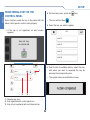
REGISTERING NEW KEYS............................................................................. 77
REGISTERING A KEY ON THE CONTROL PANEL ........................................ 78
INTRODUCTION
INTRODUCTION
WARNING
•
Comelit Group S.p.A. declines any responsibility for improper use of the apparatus, for any alterations made by others for any reason, and for
the use of non-original accessories or materials.
•
Caution! In order to reduce the risk of faults and electric shocks:
•
Do not open the apparatus or carry out any repairs yourself. If necessary, request the services of qualified personnel.
•
Do not insert objects or pour liquids into the device.
•
Clean using a damp cloth. Do not use alcohol or other aggressive products.
Fonts are (c) Bitstream (see below). DejaVu changes are in public domain.
Glyphs imported from Arev fonts are (c) Tavmjong Bah (see below)
Arev Fonts Copyright
------------------------------
Bitstream Vera Fonts Copyright
------------------------------
Copyright (c) 2006 by Tavmjong Bah. All Rights Reserved.
Permission is hereby granted, free of charge, to any person obtaining a copy of the fonts
accompanying this license ("Fonts") and associated documentation files (the "Font Software"),
to reproduce and distribute the modifications to the Bitstream Vera Font Software, including
without limitation the rights to use, copy, merge, publish, distribute, and/or sell copies of the
Font Software, and to permit persons to whom the Font Software is furnished to do so, subject
to the following conditions:
Copyright (c) 2003 by Bitstream, Inc. All Rights Reserved. Bitstream Vera is a trademark of
Bitstream, Inc.
Permission is hereby granted, free of charge, to any person obtaining a copy of the fonts
accompanying this license ("Fonts") and associated documentation files (the "Font Software"),
to reproduce and distribute the Font Software, including without limitation the rights to use, copy,
merge, publish, distribute, and/or sell copies of the Font Software, and to permit persons to
whom the Font Software is furnished to do so, subject to the following conditions:
The above copyright and trademark notices and this permission notice shall be included in all
copies of one or more of the Font Software typefaces.
The above copyright and trademark notices and this permission notice shall be included in all
copies of one or more of the Font Software typefaces.
The Font Software may be modified, altered, or added to, and in particular the designs of glyphs
or characters in the Fonts may be modified and additional glyphs or characters may be added
to the Fonts, only if the fonts are renamed to names not containing either the words "Tavmjong
Bah" or the word "Arev".
The Font Software may be modified, altered, or added to, and in particular the designs of glyphs
or characters in the Fonts may be modified and additional glyphs or characters may be added
to the Fonts, only if the fonts are renamed to names not containing either the words "Bitstream"
or the word "Vera".
This License becomes null and void to the extent applicable to Fonts or Font Software that has
been modified and is distributed under the "Tavmjong Bah Arev" names.
This License becomes null and void to the extent applicable to Fonts or Font Software that has
been modified and is distributed under the "Bitstream Vera" names.
The Font Software may be sold as part of a larger software package but no copy of one or more
of the Font Software typefaces may be sold by itself.
The Font Software may be sold as part of a larger software package but no copy of one or more
of the Font Software typefaces may be sold by itself.
THE FONT SOFTWARE IS PROVIDED "AS IS", WITHOUT WARRANTY OF ANY KIND,
EXPRESS OR IMPLIED, INCLUDING BUT NOT LIMITED TO ANY WARRANTIES OF
MERCHANTABILITY, FITNESS FOR A PARTICULAR PURPOSE AND NONINFRINGEMENT
OF COPYRIGHT, PATENT, TRADEMARK, OR OTHER RIGHT. IN NO EVENT SHALL
TAVMJONG BAH BE LIABLE FOR ANY CLAIM, DAMAGES OR OTHER LIABILITY,
INCLUDING ANY GENERAL, SPECIAL, INDIRECT, INCIDENTAL, OR CONSEQUENTIAL
DAMAGES, WHETHER IN AN ACTION OF CONTRACT, TORT OR OTHERWISE, ARISING
FROM, OUT OF THE USE OR INABILITY TO USE THE FONT SOFTWARE OR FROM OTHER
DEALINGS IN THE FONT SOFTWARE.
THE FONT SOFTWARE IS PROVIDED "AS IS", WITHOUT WARRANTY OF ANY KIND,
EXPRESS OR IMPLIED, INCLUDING BUT NOT LIMITED TO ANY WARRANTIES OF
MERCHANTABILITY, FITNESS FOR A PARTICULAR PURPOSE AND NONINFRINGEMENT
OF COPYRIGHT, PATENT, TRADEMARK, OR OTHER RIGHT. IN NO EVENT SHALL
BITSTREAM OR THE GNOME FOUNDATION BE LIABLE FOR ANY CLAIM, DAMAGES
OR OTHER LIABILITY, INCLUDING ANY GENERAL, SPECIAL, INDIRECT, INCIDENTAL,
OR CONSEQUENTIAL DAMAGES, WHETHER IN AN ACTION OF CONTRACT, TORT
OR OTHERWISE, ARISING FROM, OUT OF THE USE OR INABILITY TO USE THE FONT
SOFTWARE OR FROM OTHER DEALINGS IN THE FONT SOFTWARE.
Except as contained in this notice, the name of Tavmjong Bah shall not be used in advertising or
otherwise to promote the sale, use or other dealings in this Font Software without prior written
authorization from Tavmjong Bah. For further information, contact: tavmjong @ free. fr.
Except as contained in this notice, the names of Gnome, the Gnome Foundation, and Bitstream
Inc., shall not be used in advertising or otherwise to promote the sale, use or other dealings in
this Font Software without prior written authorization from the Gnome Foundation or Bitstream
Inc., respectively. For further information, contact: fonts at gnome dot org.
4
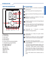
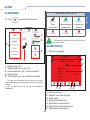
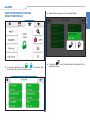
MONITOR DESCRIPTION
KEY FUNCTIONS
Audio key: activates or de-activates conversation with
the external unit.
Door lock key: opens the corresponding door lock.
1
2
:
,UULJDWLRQ
$XWRPDWLRQV
&RQVXPSWLRQ
6FHQDULRV
Menu key: switches the Planux Manager monitor on and
off.
/RDGV
Brightness key: adjusts the brightness of the image
displayed in a video message.
3
Contrast key: adjusts the contrast of the image displayed
in a video message.
4
5
14
13 12 11 10
9
8
7
Colour key: adjusts the colour of the image displayed on
the monitor. To change the setting, press the key while
video communication is in progress.
Programmable key 1: factory-set
switchboard call (programmable).
6
as
secondary
Programmable key 2: factory-set as generic actuator
(programmable).
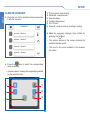
1. Microphone
2. Touch screen
3. Key sensor
4. Audio capsule
5. Door lock key
6. Privacy / Doctor key (programmable)
7. Self-ignition key (programmable)
8. Programmable key 2
9. Programmable key 1
10.Colour key
11. Contrast key
12.Brightness key
13.Menu key
14.Audio key
Self-ignition key: switches on the monitor and displays
the video feed from the external unit (programmable).
Privacy/Doctor function key (programmable):
• The Privacy function disables calls from the external
unit and switchboard.
• The Doctor function enables automatic activation of the
lock-release in response to a call from the external unit.
• The Privacy + Doctor function, as well as disabling
the door-entry phone ringtone in the same way as the
Privacy function, also enables automatic activation of
the lock-release in response to a call from the external
unit.
The red LED indicates that the selected function is
active.
5
INTRODUCTION
INTRODUCTION
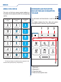
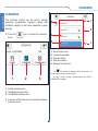
MENUS
MENUS
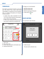
PLANUX MANAGER MENU
Press the
immediately.
The Planux Manager icons change depending on the
type of system installed and the functions available. To
navigate the menu, simply use your finger to touch the
icon corresponding to the desired function.
Press
icon to return to the main menu
to return to the previous screen.
Alarms
Press the
key or touch the display to access
the main menu.
Press the
and
menu screens.
$ODUPV
keys to navigate between
:
9LGHR6\VWHP
&OLPDWH
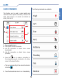
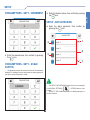
MENU "ALARM" ICON STATUS
2WKHU
%OLQGV
,UULJDWLRQ
&RQVXPSWLRQ
$XWRPDWLRQV
The "alarm" icons on the home screen provide
feedback on the alarm system status:
/LJKWV
:
Alarms
Alarms
Alarms
Alarm
deactivated
across the entire
system
Alarm activated
across the entire
system
Alarm partially
activated:
only certain areas
and/or partial zones
are activated
Alarms
Alarms
Alarms
Tampered/Faulty
Alarm memory
In alarm
/RDGV
6FHQDULRV
6
MENUS
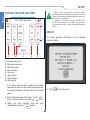
MENU ICON STATUS
The icons on the home screen provide feedback on
the status of active elements within the corresponding
section:
no elements
active
some elements
active
all elements
active
Climate
Climate
Climate
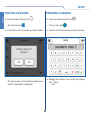
The bookmarks and favourites bar is next to the
icon.
The toolbar showing the time, date and system
consumption data in real time is just underneath.
1
Other
Other
Other
Blinds
Blinds
Blinds
Lights
Lights
Lights
Irrigation
Irrigation
Irrigation
Automations
Automations
MENUS
BOOKMARKS AND FAVOURITES
BAR AND TIME AND CONSUMPTION
TOOLBAR
2
3
:
$ODUPV
9LGHR6\VWHP
&OLPDWH
2WKHU
%OLQGV
/LJKWV
Automations
•
For blinds and shutters, the activation status corresponds to their
movement status (opening/closing - raising/lowering).
4
1.
2.
3.
4.
7
Bookmark 1
Bookmark 2
Favourites menu
Date and consumption menu
MENUS
MENUS
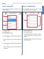
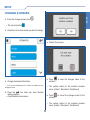
ADDING BOOKMARKS
REMOVING BOOKMARKS
To add a function to the bar, press and hold the
corresponding icon until the menu opens.
To remove a function from the bar, press and hold
the corresponding icon on the bar until the menu
opens.
5HPRYHIURPERRNPDUNV"
$ODUPV
:
'R\RXZDQWWRDGGWKHHOHPHQW
WR\RXUERRNPDUNV"
$ODUPV
%/,1'6
9LGHR6\VWHP
9LGHR6\VWHP
<(6
&OLPDWH
&OLPDWH
12
Press
to remove the function from the
bookmarks panel.
<(6
Press
2WKHU
%OLQGV
to cancel the removal procedure.
12
/LJKWV
REMOVING FAVOURITES
To remove the function from the favourites menu,
press the icon until the menu opens.
•
•
Press
panel.
to add the function to the bookmarks
Press
panel.
to add the function to the favourites
5HPRYHIURPERRNPDUNV"
$ODUPV
• Press & to cancel the procedure.
9LGHR6\VWHP
<(6
&OLPDWH
12
To remove the function from the favourites menu,
press the icon until the menu opens.
to remove the function from the
Press
bookmarks panel.
<(6
Press
8
12
to cancel the removal procedure.
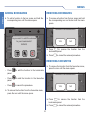
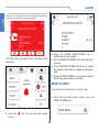
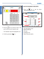
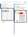
ALARM
ALARM MENU
Alarms
ALARM
Press
Alarm system status icon (5)
to access the alarm menu.
Insert total
System off
Insert partial
Alarm
deactivated
Alarm activated across
the entire system
Alarm partially
activated
Alarm memory
Alarm in progress
In sabotaggio
1
1,*+7
6\VWHP
RII
*$5'(1
2
•
The flashing icon indicates one or more faults. Press the
icon to view the details.
5
ALARM STATUS
)XOOVHW
3
√ An alarm is triggered.
)XOOXQVHW
1
4
1.
2.
3.
4.
5.
2
Settings menu icon
Timed activations icon (on / off)
Customisable icons (x2) - quick commands
System status
Customisable icon (x4) - activation command
3
8WHQWH
$]LRQH
•
The menu can be customised via the settings: add or remove
quick command and activation command connections to customise the
interface.
•
N.B.: the alarm home screen can also be customised via
SafeManager.
7
1.
2.
3.
4.
5.
6.
7.
9
6
5 4
Scroll events icon
Selected event date and time
Event details
System deactivated icon
Reset alarms command icon
Reset phone calls command icon
Stop alarms command icon
ALARM
ALARM
•
If a camera on the alarm screen is associated with the zones, an
additional icon (1) will appear to indicate that images were captured by
the camera at the moment the alarm was activated.
1
Press the ALARM DEACTIVATION key to
deactivate the alarm system.
Press the RESET ALARMS icon to reset the alarm
memory.
Press the RESET PHONE CALLS icon to delete
the memory dedicated to emergency telephone
calls.
Press the STOP ALARMS icon to stop the selected
alarm (the system remains activated).
The alarm menu also keeps track of the alarm which
has arisen.
RESET ALARMS
A reset can be performed in one of 3 ways:
1. From the main alarm menu screen, press the
RESET ALARMS icon*.
Press the
screen.
icon to open the event details
10
ALARM
TIMED ACTIVATIONS
2. If you cannot see the icon, access the alarm menu
and press the icon to access the alarm settings.
Access the alarm menu, then press the icon
/
, enter the alarm password to activate /
deactivate the timed control panel activations.
Access the QUICK COMMANDS function by
pressing the corresponding icon.
» A screen will confirm activation / deactivation of
the function.
ACTIVATING THE ANTI-INTRUSION
SYSTEM
Access the alarm menu and press the icon
to access the options menu.
Press
the
RESET ALARMS function
to reset the alarms.
icon
3. Activate (even partially) the alarm system.
•
The system does not provide any screen confirming
correct execution of the function.
Press the CUSTOMISED ACTIVATION ICON.
11
ALARM
*if previously added to the screen as described in
paragraph "QUICK COMMANDS" on page 19.
ALARM
ALARM
» An update screen opens:
Select the desired
corresponding icon.
area
by
pressing
the
» The system displays a confirmation screen.
FULL AREA ACTIVATION
Press the
area.
icon to activate the entire selected
12
ALARM
Select the desired partial zone for partial activation
and the activation type.
» The system displays a confirmation screen.
» The activated area will be highlighted in green; the
type of activation carried out will also be indicated.
PARTIAL AREA ACTIVATION
Press the
selected area.
icon to partially activate the
» The activated area will be highlighted in green; the
type of activation carried out will also be indicated.
13
ALARM
» An update screen opens:
ALARM
ALARM
Select the area you want to deactivate.
ANTI-INTRUSION SYSTEM
DEACTIVATION (1)
Access the alarm menu and press the icon
to access the alarm options menu.
icon to deactivate the system in the
Press the
selected area.
» An update screen opens:
Press the CUSTOMISED ACTIVATION ICON.
» The system displays a confirmation screen.
14
ALARM
Select the area you want to deactivate.
ALARM
ANTI-INTRUSION SYSTEM
DEACTIVATION (2)
icon to deactivate the system in the
Press the
selected zone.
Press the padlock icon
/
to access the
anti-intrusion system areas menu.
15
ALARM
ALARM
ALARM SETTINGS
CUSTOMISED ACTIVATION
Access the alarm menu and press the icon
The function can be used to view system areas and the
status associated with each of them, and to activate /
deactivate the system in the desired areas.
to access the alarm settings menu.
The displayed areas can be fully or partially activated
and deactivated.
(See ANTI-INTRUSION SYSTEM ACTIVATION and
DEACTIVATION).
Press the icon with the name of the desired
function to open the corresponding panel.
•
Every time a parameter relating to the ALARM function
is changed, the data is set to the control panel. In this case a
configuration update screen appears.
16
ALARM
ACTIVATION CONTROL
Activation connections can be added to the main
/ alarm
$ODUPV
).
icon to add the activation to the
Press the
alarm function home screen.
» The icon turns blue
.
NIGHT
•
Up to 4 different activation controls can be entered on
the main alarm screen!
GARDEN
EXIT
Event log
Scenario 1
The function can be used to view the log of events
recorded by the system and alarms triggered.
Press the icon with the relevant activation name to
run the corresponding scenario.
» An update screen opens:
Press the icon corresponding to the log you wish
to consult.
» The system displays a confirmation screen.
17
ALARM
alarm screen (home
The function can be used to run activation scenarios
created previously.
ALARM
ALARM
Press the icon to open the list of any Omitted /
Isolated / Open / Tampered - Faulty zones.
1
3
1
2
√ If there are no zones corresponding to the
condition.
8WHQWH
$]LRQH
1. Events / alarms navigation icon
2. Selected event / alarm (date + time)
3. Event / alarm details
√ If there are several zones corresponding to the
criteria.
ZONE AND AREA STATUS
The function is used to check the status of the various
zones / areas configured in the system.
•
18
You can scroll through the available areas using
the
/
icons.
ALARM
QUICK COMMANDS
The following commands are available:
ALARM
This function can be used to select which quick
command buttons (alarm commands) to move to the
alarm home screen, or to execute a command (or
alarm) from the list.
4
3
1
2
1
1. Menu navigation icons
2. List of quick commands available
3. Icon for connection on alarm home screen
(deactivated)
4. Icon for connection on alarm home screen
(activated)
Press the
icon to create a connection to
the corresponding quick command on the home
screen for the alarm function.
» The icon corresponding to the selected command
.
turns blue
Press the desired alarm icon to run it immediately.
19
ALARM
ALARM
OUTPUT COMMAND
This function can be used to change the status of the
system outputs.
ALARMS
4
2XWSXW
3
2XWSXW
1
2
2XWSXW
2XWSXW
1
1. Menu navigation icons
2. List of output commands available
3. Icon for connection on alarm home screen
(activated)
4. Icon for connection on alarm home screen
(deactivated)
Press the
icon to create a connection to the
corresponding command function on the alarm
home screen.
» The icon corresponding to the selected output
turns blue
.
20
ALARM
Press the icon for the desired output to change
its status.
PHONE BOOK
1
4
•
•
•
2
3
Select the desired status.
SET to activate the output
UNSET to deactivate the output
TOGGLE to change the status (if active it will be
deactivated and vice-versa)
1
» The system confirms completion.
1.
2.
3.
4.
Scroll screen icons
Edit contact email
Edit contact telephone number
Edit contact name
•
21
The control panel can memorise up to 16 contacts.
ALARM
This function can be used to edit the phone book
memorised on the control panel.
ALARM
ALARM OPTIONS
ALARM
Select the icon corresponding to the parameter to
be edited.
The options panel contains a series of sub-menus
dedicated to the various alarm system settings.
1$0(
Make the desired changes, then confirm with the
icon.
Press the desired icon to open the corresponding
panel.
» The system confirms completion.
» The system updates.
22
ALARM
Confirm the process.
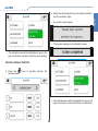
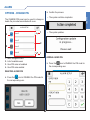
OPTIONS - CHANGE PIN
$/$506(783
4
8VHU
» The system updates.
1
8VHU
2
3
8VHU
8VHU
1.
2.
3.
4.
1
ADDING A USER PIN
Menu navigation icons
List of available users
User PIN code not enabled
User PIN code enabled
Press the
icon to ENABLE the PIN code for
the corresponding user.
DELETING A USER PIN
icon to DISABLE the PIN code for
Press the
the corresponding user.
23
ALARM
» The system confirms completion.
The CHANGE PIN panel can be used to change or
delete the pin codes associated with users.
ALARM
ALARM
Enter the PIN code and confirm it by pressing the
icon on the dedicated screen.
Enter the PIN code and confirm it by pressing the
icon on the dedicated screen.
» The system confirms completion.
» The system confirms completion.
» The system updates.
» The system updates.
CHANGING A USER PIN
Press the icon corresponding to the desired user.
24
ALARM
OPTIONS - VOICE MENU
» The system updates.
ALARM
The option - if enabled - can be used to partially
manage and monitor the control panel via telephone
calls.
√ To use the function, a GSM COMMUNICATION
CARD Art. 30001301 and a VOICE MESSAGE
CARD Art. 30001303 must have been installed.
» The icon turns blue
.
DISABLING THE VOICE MENU
Press the
icon corresponding to the VOICE
MENU icon to DISABLE the function.
» The system confirms completion.
» The system updates.
ENABLING THE VOICE MENU
Press the
icon corresponding to the VOICE
MENU icon to ENABLE the function.
» The icon turns grey
» The system confirms completion.
25
.
ALARM
» The system updates.
ALARM
OPTIONS - INSTALLER
The option enables / disables installer mode in control
panel system parameters.
» The icon turns blue
.
DISABLING THE INSTALLER
Press the
icon corresponding to the
INSTALLER icon to DISABLE the function.
» The system confirms completion.
ENABLING THE INSTALLER
» The system updates.
Press the
icon corresponding to the
INSTALLER icon to ENABLE the function.
» The system confirms completion.
» The icon turns grey
26
.
ALARM
OPTIONS - TIMER
» The system updates.
ALARM
The option can be used to enable / disable the alarm
control panel activation timers.
1
» The icon turns blue
DEACTIVATING THE TIMER
4
2
Press the
icon
corresponding timer.
3
to
Menu navigation icons
List of available timers
Timer not active
Timer active
» The system updates.
ACTIVATING THE TIMER
Press the
timer.
DEACTIVATE
» The system confirms completion.
1
1.
2.
3.
4.
.
icon to ACTIVATE the corresponding
» The system confirms completion.
» The icon turns grey
27
.
the
ALARM
Confirm the deletion.
ALARM
OPTIONS - SET UP DESKTOP
» The system confirms completion.
The option can be used to delete connections to
Activation controls / Quick commands / Output
commands previously added to the alarm home
screen.
» The system updates.
OPTIONS - TONES
The function can be used to manage (enable or
disable) the various alert tones (audible signals)
emitted by the control panel.
Press the
connection.
icon to delete the corresponding
2
1
1. "Tones" sub-menu icon for enabling individual
tones
2. Enable / disable tone replaying icon
28
ALARM
Press the "Tones" icon (1) to enter the sub-menu.
Selecting or deselecting the function using the
The sub-menu can be used to select which audible
signals you want to be replayed by the control panel
and which you do not.
» The system confirms completion.
1
4
» The system updates.
3
2
1
» The icon changes status
/
.
1.
2.
3.
4.
Menu navigation icons
List of audible signals available
Signalling enabled
Signalling disabled
Select the audible signals by pressing the
icon.
» The selected audible signal icons turn blue
29
.
ALARM
/
icons (2) enables replaying of the audible
signals selected in the "Tones" sub-menu (1).
ALARM
ALARM
ENABLING ALERT TONES
» The system updates.
Press the
icon to ENABLE the corresponding
audible signalling.
» The system confirms completion.
» The icon turns grey
.
» The system updates.
OPTIONS - CONFIGURATION
» The icon turns blue
.
DISABLING ALERT TONES
Press the
icon to DISABLE the corresponding
audible signalling.
» The system confirms completion.
Select the entry you wish to change by pressing
the corresponding icon.
30
ALARM
RS485 BUS ADDRESS
DEVICE PASSWORD
Enter the desired value, then confirm by pressing
icon.
the
Enter the desired code, then confirm by pressing
the
icon.
BUS RS485 SPEED
•
Default device code: 0 (zero)
USER CODE
$/$506(783
Press the
icon to select the desired value.
» The icon turns blue
•
.
Default Comelit BUS speed: 38400
31
Enter the desired code, then confirm by pressing
the
icon.
ALARM
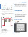
$/$506(783
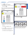
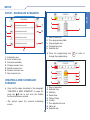
FUNCTIONS
FUNCTIONS
OTHER / BLINDS /
LIGHTS / IRRIGATION / AUTOMATIONS
•
LIGHTS section illustrative example
/,*+76
Press
/ %OLQGV /
/
to access the relevant sections.
/LJKWV
$ODUPV
,UULJDWLRQ
1
/,*+76
2))
URRP
21
2))
URRP
21
2))
URRP
21
2))
URRP
21
6
1.
2.
3.
4.
5.
6.
5
/
2))
URRP
21
2))
URRP
21
2))
URRP
21
2))
URRP
21
1
$XWRPDWLRQV
2
2
3
1. Room completely deactivated
2. Room partially activated
3. Room fully activated
21
2))
Press
/
to activate / deactivate rooms or
individual elements.
3
4
•
For blinds, the
21
/
2))
buttons will be replaced by
/
.
Press
then select the desired room to
access the room scheduling functions (see
scheduling section).
Panel description
Scroll screen icons
Scheduling icon
ON icon
Available rooms
OFF icon
Press the room icon to view the menu of the
individual elements it contains.
32
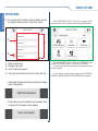
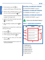
FUNCTIONS
TIMED FUNCTIONS
1
Some functions can be timed: an activation time can
be set for the function.
5RRP
2
/LJKW
timed functions
3
T
/LJKW
T
/LJKW
T
1. Selected room
2. Commands for scrolling between the available
rooms
3. Details of the elements making up the room
21
Press
/
elements.
2))
timed other
timed light
timed irrigation
Press the relevant icon to open the timing menu.
to activate / deactivate individual
,55,*$7,21
then select the desired element
Press
to access the scheduling functions (see
scheduling section).
Adjust the time using the
confirm the procedure
.
33
keys and
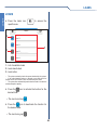
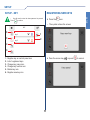
FUNCTIONS
/,*+76
SCHEDULING
SCHEDULING
SCHEDULING
Press
/ %OLQGV / /LJKWV /
to access the relevant sections.
2WKHU
,UULJDWLRQ
/
$XWRPDWLRQV
Press
, then select the area you want to
schedule.
» The icon will turn blue before the desired area is
.
selected
1
5
The previously selected day can be changed by
pressing the bar above the corresponding icon.
4
» The selected day or days are highlighted in red.
2
3
Press
+ to add a programming to the list.
Set the time using the
keys and press
to confirm.
1.
2.
3.
4.
5.
Days of week bar
Time / status table
Copy program icon
Programming icon
Selected day
Select the desired day and press the
enter the programming screen.
Set the desired status using the
press
to confirm.
keys and
» The feature being changed will be highlighted in
yellow.
352*
icon to
34
SCHEDULING
SCHEDULING
FUNCTIONS
Press
to delete a programming.
When programming is complete, return to the
previous screen
.
Once you have returned to the main screen you will
be able to copy the activity programming for a specific
day to others:
Confirm by pressing the
icon.
Scheduling icons
Select the day of the week to copy from the band
at the top.
scheduling
NOT PRESENT
memorised
scheduling NOT
ACTIVE
memorised
scheduling active
» The original day is highlighted in yellow.
Some icons can be used to indicate whether a
schedule linked to a specific function is present.
icon and select the days of the
Press the
week to which you want to apply the copy.
» The "destination" days will be highlighted in red.
35
ADVANCED LIGHTS
ADVANCED LIGHTS
DIMMER LIGHTS
Press 21 /
output on / off.
DIMMABLE LIGHTS (adjustable intensity)
living
GLPPHU
GLPPHU
5
GLPPHU
1.
2.
3.
4.
5.
6.
to switch the corresponding
» The indicator is completely empty when the output
is off.
/,*+76
6
2))
Press and hold
intensity.
1
21
/
2))
to adjust the light
» The intensity indicator fills up gradually as the light
intensity increases.
2
3
DIMMER LIGHT SCHEDULING
4
2
Scheduling icon
Scroll screen icons
Exit icon
ON icon
OFF icon
Area selection
1
dimmer scheduling icons
off
2
3
1. Times column
2. Status column (ON / OFF)
3. Intensity adjustment column
maximum intensity
Set the time and status as described in the
paragraph "SCHEDULING" on page 34.
Set the desired intensity using the same entry
methods.
scheduling present and active
scheduling present but not active
36
DIMMER / PRESENCE LIGHTS
Switching the presence sensor on / off.
•
Press the icon corresponding to the output (3) to enable or disable
the presence function (presence function disabled = operation as
normal dimmer).
DIMMER / PRESENCE LIGHTS
(adjustable intensity / presence sensor)
Presence detected:
•
The PRESENCE DIMMER function, using a motion sensor, can
be used to increase the brightness of the dimmer light if presence is
detected, and to decrease it to the courtesy level - or switch it off - if no
presence is detected.
•
The output comes on (at the last light intensity value set) for a preestablished period of time.
•
Press and hold commands can be used to dim the value (only while
the output is still active).
•
When the presence sensor is ON, the output cannot be controlled
with ON/OFF press and release commands.
/,*+76
Presence not detected:
5
4
1.
2.
3.
4.
5.
box
dimmer/presence
1
•
A courtesy value can be set for activation under the "absent"
condition (presence not detected).
•
When the time period has elapsed, the output will revert to the
courtesy value.
2
DIMMER / PRESENCE LIGHT
SCHEDULING
3
Scheduling icon
ON icon
Exit icon
OFF icon
Area selection
•
Presence sensor activation
scheduling (even if present!).
automatically
omits
dimmer / presence icons
presence function active
presence function not active
(the light functions as a normal dimmer)
scheduling present and active
(the light functions as a scheduled dimmer)
scheduling present but not active
Schedule as described in the paragraph "DIMMER
LIGHT SCHEDULING" on page 36.
37
ADVANCED LIGHTS
ADVANCED LIGHTS
ADVANCED LIGHTS
ADVANCED LIGHTS
RGB LIGHTS
RGB LIGHT SCHEDULING
RGB LIGHTS (adjustable colour and intensity)
/,*+76
1
1
2
1. Times column
2. RGB colour column
3. Intensity column (
3
2
3
= OFF)
Schedule by entering the desired times as
described in the paragraph "SCHEDULING" on
page 34.
Set the colour and intensity values using the same
method.
1. Colour spectrum
2. Dimmer intensity adjustment
3. Selected colour indicator
Select the colour by pressing the colour spectrum
indicator.
Adjust the intensity to the desired level by pressing
icons.
the
For more precise colour selection, press the
indicator for the selected colour (3), then enter the
numerical RGB values on screen.
38
CLIMATE
CLIMATE CONTROL
&/,0$7(
Press
to access the climate menu.
&/,0$7(
4
3
2
r
$
2
9
r
0
3
7
8
1
Scroll screen icons
List of available rooms
Room with air conditioning off
Room with air conditioning on
room
by
pressing
6
5
1. Room selection
2. Automatic mode icon
3. Manual mode icon
4. Manual forcing icon
5. Boiler
/ air-conditioner
on indicator
6. Room temperature detected
7. Desired temperature adjustment
8. Selected room on/off icon
9. Scheduling menu icon
10.Summer
/ winter
mode selection
EHGURRP
Select the desired
corresponding icon.
4
21
OLYLQJ
EDWKURRP
1.
2.
3.
4.
10
1
NLWFKHQ
1
OLYLQJ
the
Press
ON
OFF
/
to switch the system on / off.
Press
/
to activate automatic / manual
mode respectively.
» The active icon turns blue
Press
39
/
/
to change mode.
.
CLIMATE
The climate section can be used to monitor, adjust and
program the temperature of rooms.
CLIMATE
CLIMATE
CLIMATE FORCING
CLIMATE SCHEDULING
If necessary, it is possible to force programming (automatic
or manual) for a set period of time (hours or days).
In the menu for the relevant area, press the
Press
on the climate screen to access the
climate scheduling function.
icon.
•
Daily climate control programming must refer to the
whole 24-hour cycle; any hours not programmed by the user
will be set by the system automatically.
1
2
3
4
Set the temperature and forcing period duration
values, then press START.
5
1.
2.
3.
4.
5.
6.
7.
» The START icon is replaced.
» The icon
will turn blue
.
6
7
Days of week band
Programming icon
Copy program icon
View programming histogram icon
Start time column (FROM)
End time column (TO)
Temperature column
Select the desired day of the week by pressing the
corresponding icon on the band at the top (1); then
press the programming icon 352* .
•
Once the forcing cycle has finished the system will revert to the
mode set previously (Automatic or Manual).
40
CLIMATE
9
2
COPYING PROGRAMMING
3
8
1
2
7
6
5
2
4
3
1. Days of week band
2. Screen navigation icons
3. Selected box
4. Desired temperature column (T°)
5. End time column (TO)
6. Start time column (FROM)
7. Confirm icon
8. Change selected value icon
9. Selected value icon
10.Selected day
2
1. Days of week band
2. Screen navigation icons
3. Copy program icon
Select the day of the week to copy from the band
at the top.
Set the desired time bands in the end time column
(5), assigning the selected temperature to each
using the change value icons.
» The original day is highlighted in yellow.
Always confirm each entry using the confirm icon
.
•
It is possible to only adjust the "TO" end time column;
the programming start values will be generated automatically
by the system.
41
CLIMATE
10
1
To change a value entered previously, select the
desired value - highlighted in yellow (3) - then
make the changes using the value change icons
(8).
CLIMATE
CLIMATE
CLIMATE PROGRAMMING GRAPH MODE
Press the
icon to view
programming graphics screen.
the
climate
5
1
4
3
Press the
icon and select the days of the
week to which you want to apply the copy.
1.
2.
3.
4.
5.
» The "destination" days will be highlighted in red.
Confirm by pressing the
icon.
42
Time band selection icons
Revert to table view
Time axis
Temperature axis
Days of the week selection
1
2
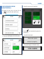
VIDEO SYSTEM
Press the 9LGHR6\VWHP / 9LGHR6\VWHP icon to open the
VIDEO SYSTEM menu.
√ The LEDs corresponding to the audio and door
lock keys flash on receipt of a call.
Press the
key to activate the audio line with
the external unit from which the call originated.
Press
to activate the corresponding door lock.
VIDEO SYSTEM MENU
Press the desired icon to open the corresponding
panel.
» When there are NEW MESSAGES part of the
video system icon will turn blue.
43
VIDEO SYSTEM
ANSWERING A CALL
VIDEO SYSTEM
VIDEO SYSTEM
VIDEO MEMORY
•
The Video memory function, if activated, can be used to record
the image from the external unit camera when a call is made, for a
maximum of 100 recordings of max. 10 seconds each.
•
Recordings are saved in .avi format on the SD card, in the “Video”
folder, and may also be viewed on a PC equipped with an SD card
reader (or adapter).
VIEWING A RECORDING
» When there are NEW MESSAGES part of the
video memory icon will turn blue.
To view one of the recordings, press the
corresponding icon.
Press the video memory icon to view the saved
messages.
» When it has finished replaying, the system will
automatically return to the previous screen.
•
Viewed recordings are highlighted with a green frame (4).
•
NEW recordings which have not yet been viewed do not have a
frame.
9,'(26<67(0
5
1
4
2
DELETING A RECORDING
Press the & icon, then select the recording you
wish to delete.
3
1.
2.
3.
4.
5.
1
Scroll screen icons
NEW message to view
Video messages present in the memory
Message already viewed
Delete message icon
Confirm the deletion.
44
VIDEO SYSTEM
CAMERAS
To view the list of actuators present, access the
specific menu Video system > Actuators.
To view the list of cameras present, access the
specific menu Video system > Cameras.
9,'(26<67(0
9,'(26<67(0
FDPHUD
DFWXDWRU
3
DFWXDWRU
3
1
FDPHUD
1
FDPHUD
DFWXDWRU
2
2
1. Scroll screen icons
2. Change name icon
3. List of actuators present
FDPHUD
1. Scroll screen icons
2. Change name icon
3. List of cameras present
Press the desired actuator icon to activate it.
Press the desired camera icon to view live images.
» A message confirms that the procedure has taken
place successfully.
•
Up to 3 cameras can be connected for each icon; these will be
displayed cyclically.
Actuator command sent
Press anywhere on the screen to return to viewing
the available cameras.
» If the actuator is not available, the message
“Device not present” will appear on the display.
» If the camera is not available, the message
“Device not present” will appear on the display.
(see actuator)
•
To add / change / rename / delete cameras, see "ACTUATORS /
CAMERAS / INTERCOMS / SELECTIVE INTERCOMS" on page 87.
Device not present
•
To add / change / rename / delete actuators, see "ACTUATORS /
CAMERAS / INTERCOMS / SELECTIVE INTERCOMS" on page 87.
45
VIDEO SYSTEM
ACTUATORS
VIDEO SYSTEM
VIDEO SYSTEM
INTERCOMS
To view the list of intercom calls available, access
the specific Video system > Intercoms menu.
•
When BACKPLATE 6214KC is fitted (also contained in KITS
20001001K and 8171M) the system does not manage INTERCOMS!
9,'(26<67(0
9,'(26<67(0
LQWHUFRP
3
LQWHUFRP
1
9LGHRPHPRU\
$FWXDWRUV
&DOOV
+DQGVIUHH
&DPHUDV
LQWHUFRP
2
LQWHUFRP
1. Scroll screen icons
2. Change name icon
3. List of intercoms present
•
When BACKPLATE 6214KC is fitted the "INTERCOMS" menu
option is NOT OFFERED; only the "CALLS" option is PRESENT.
•
The function will therefore also be absent in other specific menus
and options panels.
Press the desired intercom icon to make the call.
•
To add / change / rename / delete cameras, see "ACTUATORS /
CAMERAS / INTERCOMS / SELECTIVE INTERCOMS" on page 87.
» A message confirms that the procedure has taken
place successfully.
,QWHUFRPH[HFXWHG
» If the intercom is not available, the message “User
not present” will appear on the display.
8VHUQRWSUHVHQW
46
VIDEO SYSTEM
Select the required function, then specify the
output you wish to rename.
•
When BACKPLATE 6214KC is fitted the "CALLS" menu is replaced
by a special simplified version containing the SINGLE-FAMILY CALL
and TWO-FAMILY CALL functions.
•
The MAIN SWITCHBOARD and CARETAKER functions are NOT
present.
•
The
SECONDARY
SWITCHBOARD
is
replaced
by
SWITCHBOARD.
9,'(26<67(0
DFWXDWRU
9,'(26<67(0
6LQJOHIDPLO\FDOO
7ZRIDPLO\FDOO
Enter the desired name, then confirm with
.
CALLS
6ZLWFKERDUG
To view the list of calls available, access the
specific Video system > Calls menu.
6LPSOHEXVDODUP
HANDS-FREE
1
Press the
function.
2
+DQGVIUHH
icon to enable the "Hands-free"
» The hands-free function causes automatic
activation of the audio line on receipt of a call,
without pressing the
key.
» The icon will turn blue
1. List of available calls
2. Scroll screen icons
47
+DQGVIUHH
.
VIDEO SYSTEM
RENAMING ACTUATORS / CAMERAS /
INTERCOMS
LOADS
LOADS
LOADS
Press the loads icon
specific area.
/RDGV
to access the
/2$'6
3
ORDG
ORDG
1
2
ORDG
ORDG
1. List of available loads
2. Load deactivated
3. Load active
•
The system constantly checks the power absorbed by the system.
•
If the value detected reaches or exceeds a set safety level, the
system cuts off active loads to lower the total absorption value.
•
The system then automatically reactivates the loads in line with the
system absorption capacity.
Press the
icon to activate the function for the
desired load.
» The icon turns blue
.
Press the
icon to deactivate the function for
the desired load.
» The icon turns grey
.
48
CONSUMPTION
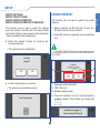
Period
kWh
0-1
0.001
from 0% to 75%
1-2
475.0
from 75% to 100%
2-3
596.0
over 100%
The consumption function can be used to monitor
consumption via graphs and tables.
Press the
menu.
&RQVXPSWLRQ
icon to access the consumption
1
9
8
7
6
5
CONSUMPTION
2
•
•
CONSUMPTION / PRODUCTION
COMPARISON
If production units are fitted (e.g. photovoltaic panels),
the system can provide a comparison between
production and consumption.
3
7
6
4
1. Period displayed
2. Change displayed time interval icon (Day / Month
/ Year / Log)
3. Scroll through available days / months / years / log
4. Change display (graph / table)
5. Consumption / time graph area
6. Total value of consumption in graph
7. Instant consumption value
8. Change unit of measurement / currency
9. Scroll through available meters
•
CONSUMPTION
CONSUMPTION
If the maximum consumption thresholds are set,
the consumption limits are shown:
In "graph" mode: yellow line from 75% to 100%,
red line over 100%.
In "table" mode: the boxes are coloured to indicate
49
the consumption level.
CONSUM. / PROD.
1
2
2
3
5
1.
2.
3.
4.
5.
6.
7.
4
Change displayed time interval icon
Scroll through available days / months / years
Change display (graph / table)
Production graph
Consumption graph
Scroll through available graphs
Change unit of measurement / currency
SCENARIOS
SCENARIOS
SCENARIOS
6&(1$5,26
The scenarios function can be used to activate
previously programmed scenarios (along with
conditions relating to the home automation system
devices).
Press the
menu.
6FHQDULRV
5
1
VFHQDULR
VFHQDULR
icon to access the scenarios
4
3
1.
2.
3.
4.
5.
2
VFHQDULR
VFHQDULR
1
Scroll screen icons
Scenarios available
Scenario active
Scenario inactive
Rename scenario icon
•
The
icon denotes the presence, within the scenario, of a
function linked to the anti-intrusion system.
1
2
•
To create / rename / change / delete scenarios, see "SETUP SCENARIOS" on page 66.
3
1. Instant scenarios icon
2. Scheduled scenarios icon
3. Conditioned scenarios icon
Press one of the three icons to access the desired
scenarios menu.
50
SCENARIOS
ACTIVATING A SCENARIO
RENAMING A SCENARIO
Press the
SCENARIOS
Press the icon for an inactive scenario to activate
it.
Confirm the activation.
icon.
» The icon turns blue
.
Select the scenario you wish to rename.
Use the virtual keypad to rename the scenario as
desired.
1$0(
» The scenario icon will turn blue.
DEACTIVATING A SCENARIO
Press the icon for an active scenario to deactivate it.
Confirm the deactivation.
Confirm the change by pressing the
» The scenario icon will turn white.
51
icon.
SETUP
SETUP - GENERAL PARAMETERS
SETUP
SETUP MENU DESCRIPTION
Press
to access the setup menu.
2
2
1
1
1. Scroll menu icons
2. General parameters menu options available
To access the desired sub-menu, press the icon
for the corresponding menu.
1. Scroll menu icons
2. Setup menu options available
» The options available are: Language / Lock keys
and touch / Set date and time / Information /
Volume adjustment.
To access the desired sub-menu, press the icon
for the corresponding menu.
» The options available are: General parameters
Video System / Conditions / Consumption / Antiintrusion / Scenarios / Key / Protection / Advanced.
52
SETUP
LANGUAGE
The interface language can be changed.
The function can be used to lock all device keys and
the touch screen for 60 s, to allow cleaning to take
place.
3
1
2
1. Scroll menu icons
2. Languages available
3. Language selected
Select the desired language by pressing the
relevant icon.
Confirm the process.
» When the period of 60 s has elapsed, the device
unlocks automatically.
Confirm your choice.
•
When a Vedo control panel is fitted, the language is set
automatically to match the one used by the control panel
itself, ignoring the selected option.
53
SETUP
LOCKING THE KEYPAD AND TOUCH
SCREEN
SETUP
SETTING THE DATE AND TIME
SETUP
•
When a Vedo control panel is fitted, the device
automatically receives time and date setting information from
the alarm control panel (changes still affect the device and
other supervisors connected).
•
Otherwise, the function for setting automatic DST/
non-DST time switching is also enabled, with the option
of customising the dates or using the standard European
settings.
1
ABOUT
The menu provides information on the software
version installed.
2
8
1.
2.
3.
4.
5.
6.
7.
8.
7 6
5
4
3
Increase value icon
Decrease value icon
Minutes column
Hours column
Save icon
Year column
Month column
Day column
√ If an alarm control panel is fitted, time setting
becomes an alarm function and therefore requires
the alarm password; changes affect the control
panel.
Press
Set the desired values for the day / month / year /
hours / minutes options using the
/
icons.
When you have finished, save the new
configuration using the
button.
54
to exit the screen.
SETUP
SETUP - VIDEO SYSTEM
ADJUSTING THE VOLUME
SETUP
The Ringtone / Audio / Intercom / Keys / Alarm audio
volume can be adjusted.
1
2
3
1. Melody selection icon
2. Option active
3. Option deactivated
SETTING MELODIES
The call melody can be changed.
Press the "Set Melodies" icon.
Press the icon for the desired function.
» A panel opens, showing the various call types.
and
icons,
Adjust the volume using the
then press the
icon to confirm and exit the
screen.
55
SETUP
SETUP
Select the call type for which you want to change
the melody.
MULTIPLE ADDRESS
When the function is activated, the monitor will ring
every time a Simplebus address within the set range
is called.
» A panel opens, showing the various melodies
available.
Press the
icon to activate the function.
» The icon turns blue
Press the
.
icon to deactivate the function.
» The icon turns grey
.
For configuration of the range of addresses, see the
advanced setup option "ADDRESSES" on page 90.
VIDEO MEMORY
The video memory function can be enabled / disabled.
Press the
Select the desired melody by pressing the
icon.
» The icon turns blue
•
icon to activate the function.
» The icon turns blue
.
Press the
.
icon to deactivate the function.
Press the icon showing the name of the ringtone to listen to it.
» The icon turns grey
56
.
SETUP
SETUP - CONSUMPTIONS
Some previously programmed conditions can be
enabled / disabled.
The consumption menu can be used to manage
various options linked to consumption.
&21',7,216(783
1
2
FRQGLWLRQ
2
FRQGLWLRQ
1
FRQGLWLRQ
3
FRQGLWLRQ
1. Condition inactive
2. Condition active
3. List of available conditions
Press the
21
1. Screen navigation icons
2. List of available options
» The options available are: Toolbar / Currency /
K CO2 / Display / Rates / Thresholds / Reset /
Settings.
icon to enable the desired condition.
Press the icon for the desired function to open the
corresponding menu.
» The icon showing the name of the condition turns
blue.
Press the
2))
icon to disable the desired condition.
» The icon showing the name of the condition turns
white again.
57
SETUP
SETUP - CONDITIONS
SETUP
SETUP
TOOLBAR
CURRENCY
You can select which meter to view - from the available
options - using the main menu toolbar.
You can select the desired currency for viewing costs
linked to consumption.
√ To view consumption, the rates must be set (see
SETUP / CONSUMPTIONS / RATES).
&2168037,216
PHWHU
&2168037,216
3
PHWHU
2
1
PHWHU
PHWHU
1. Screen navigation icons
2. Selected meter
3. List of available meters
Press the
icon corresponding to the desired
rate to select it.
Press the
icon corresponding to the desired
meter to select it.
» The icon turns blue
•
» The icon turns blue
.
Only one meter can be selected at a time!
58
.
SETUP
K CO2
&2168037,216
&2168037,216
If you select the option CUSTOMISED, you can give
a customised name of 3 letters/digits to the currency.
Enter the desired name, then confirm by pressing
the
icon.
Set the desired K CO2 value, then confirm with
.
√ Consult the system installer regarding the K CO2
value.
59
SETUP
If energy production systems (photovoltaic, etc.) are
fitted, you can enter the CO2 constant in order to
monitor the CO2 not released into the environment.
SETUP
SETUP
DISPLAY
DISPLAY - RENAME METER
You can select which meters to view from the available
options.
The meters can be renamed.
Press the
to rename.
&2168037,216
5
1
PHWHU
&2168037,216
PHWHU
2
4
PHWHU
PHWHU
3
PHWHU
1.
2.
3.
4.
5.
icon, then select the meter you wish
Change meter name icon
List of available meters
Scroll screen icons
Deselected meter
Selected meters
Press the
icon to select the desired meter.
Enter the desired name, then confirm by pressing
the
icon.
» The icon turns blue
Press the
icon to deselect the meter.
» The icon turns grey
•
.
.
Several meters can be selected at once!
60
SETUP
RATES
» The information will be used to construct the
consumption graphs in the Consumption menu.
352*
icon to
The previously selected day can be changed by
pressing the bar above the corresponding icon.
» The selected day or days are highlighted in red.
&2168037,216
(OHFWFRQVXPSWLRQ
:DWHUFRQVXPSWLRQ
)LUVWIORRUJURXS
» Select the desired meter.
1
5
Select the desired time, set the time using the
keys and press
to confirm.
4
2
» The feature being changed will be highlighted in
yellow.
3
1.
2.
3.
4.
5.
Days of week bar
Time / price table
Copy program icon
Programming icon
Selected day
•
Daily rate programming should refer to the entire 24-hour
period of one day! Any hours not programmed by the user will
automatically be set by the system.
61
SETUP
Select the desired day and press the
enter the programming screen.
The meter rates can be set according to time bands.
SETUP
SETUP
Set the desired unit price.
Programming can be copied from a specific day to
other days of the week:
•
EXAMPLE: set the cost of 1 kWh with a value of 20 Euro cents
per unit.
•
20 cent/euro = 0.020 €
•
enter the value 0.020 on the screen
Press the
icon.
Select the desired days using the bar at the top.
Confirm copying by pressing the
Enter the desired value, then confirm by pressing
icon.
the
62
icon.
SETUP
To change one or more thresholds:
The maximum consumption thresholds can be set by
Hour / Day / Month / Year in order to obtain instant
visual feedback, on the graph and in the consumption
table, as to whether the threshold set for that period
has been exceeded.
1.
2.
3.
4.
» In "graph" mode: yellow consumption line from
75% to 100% of the set threshold, red consumption
line over 100% of the set threshold.
» In "table" mode: the boxes are coloured using the
same criteria to indicate the consumption level.
PHWHU
Select the desired meter.
Select the desired value.
Enter the new value for that period.
Confirm with the
icon.
RESET (METERS)
The reset function resets all meters.
1
2
3
4
1.
2.
3.
4.
Select meter
Value entered / set
Period / threshold table with set threshold values
Selected threshold value
Confirm the reset.
» The meters will be set back to zero.
63
SETUP
THRESHOLDS
SETUP
SETUP
CONSUMPTIONS - SETTINGS
CONSUMPTIONS - SETT. - UNIT OF MEASUREMENT
The function can be used to change some features of
the installed meters.
&2168037,216
&2168037,216
*$6
:$7(5
Select the desired meter from the available
options.
Enter the desired value, then confirm by pressing
icon.
the
» A panel opens, showing the adjustable features
of the meter.
CONSUMPTIONS - SETT. - PULSES
√ EXAMPLE: the pulse meter measures 1 mc every
10 pulses; set the PULSE and INCREMENT
options with values 10 and 1 respectively.
&2168037,216
Select the feature to be changed:
Enter the desired value, then confirm by pressing
the
icon.
64
SETUP
Enter the desired value, then confirm by pressing
icon.
the
CONSUMPTIONS - SETT. - INCREMENT
SETUP
SETUP - ANTI-INTRUSION
&2168037,216
Enter the alarm password, then confirm by
pressing the
icon.
$/$506(783
4
8VHU
1
8VHU
2
3
Enter the desired value, then confirm by pressing
icon.
the
8VHU
8VHU
CONSUMPTIONS - SETT. - SCALE
FACTOR
1
•
This parameter is used to set conversion of the unit of measurement
displayed. For example, if using a calorie meter for heating systems but
you want to see the information in Joules.
&2168037,216
•
The SETUP / ANTI-INTRUSION section of the menu corresponds
) / OPTIONS section of this
to the ALARM / SETTINGS (
manual.
•
REFER TO THE ALARM SECTION for a detailed description of
the menu functions.
65
SETUP
SETUP
SETUP - SCENARIOS
SETUP - INSTANT SCENARIOS
The menu can be used to create, rename, change
or delete one or more scenarios in one of the three
available categories.
6&(1$5,26
6
VFHQDULR
5
4
VFHQDULR
3
VFHQDULR
1.
2.
3.
4.
5.
6.
Press the corresponding icon to open the desired
category.
1
2
VFHQDULR
1
Scroll screen icons
Scenarios available
Change scenario icon
Delete scenario icon
Rename scenario icon
New scenario icon
ACTIVATING SCENARIOS
Press the icon corresponding to the desired
scenario to run it.
66
SETUP
CREATING A NEW SCENARIO
.
Press the icon for the desired function to associate
it with the scenario.
1$0(
» The panel corresponding to the selected function
opens; this can be used to choose which specific
features of the function to enable (e.g. zones,
scheduling, status...).
6&(1$5,26
VFHQDULROLJKW
1
VFHQDULROLJKW
2
5
4
3
VFHQDULROLJKW
Assign a name to the scenario, then confirm by
icon.
pressing the
VFHQDULROLJKW
» A screen shows the functions available when the
scenario is activated.
1.
2.
3.
4.
5.
Icon identifying the selected function
Scroll screen icons
Select room / output icon
Icon with room name / name of individual output
Rooms / outputs available
Press the
67
icon to select the entire room.
SETUP
Press the new scenario icon
» The functions that can be associated with a
scenario are: Climate / Other / Blinds / Lights /
Irrigation / Automations / Video system / Alarm.
SETUP
SETUP
Set the desired status by pressing
corresponding icon, then confirm with
.
1
5
» The icons will turn blue
the
.
2
3
1.
2.
3.
4.
•
For BLINDS, the ON / OFF icons are replaced by the
icons respectively.
•
For RGB and DIMMER LIGHTS, there will also be colour and
intensity adjustment icons.
•
For the VIDEO SYSTEM, only the scenario DELAY TIME can be
set.
•
For the ALARM function, the ALARM CODE must be ENTERED
before you can enable the desired alarm function.
•
For a detailed description of each function (Alarm / Video system /
Climate / Other / Blinds / Lights / Irrigation / Automations), refer to the
specific chapters in the manual.
On status icon
Scenario delay
Confirm icon
Off status icon
Set
the
desired
status
by
pressing
corresponding icon, then confirm with
the
.
One or more individual outputs can be entered in a
scenario:
Once you ave finished entering the desired
functions, press the
icon to exit.
Press the icon with the name of the zone / room,
then select the desired outputs using the
icons.
» A confirmation screen opens.
6&(1$5,26
21(
7:2
7+5((
68
SETUP
Confirm the process.
FUNCTION DELAY
In the window used to enter the function as part of
the scenario, press the scenario delay icon
.
Press
scenario.
to save the changes made to the
» The system returns to the selected scenario
menu. (Instant / Scheduled / Conditioned)
Press &
scenario.
to cancel the changes made to the
Set the desired delay time using the
and
icons (minutes : seconds), then confirm by
icon.
pressing the
» The system returns to the selected scenario
menu. (Instant / Scheduled / Conditioned)
» The icon
69
will turn green.
SETUP
By entering a delay time, the commands entered
in a scenario can be executed with a pre-set delay.
For example, the outside lights of a walkway can be
switched on in sequence, one every 5 seconds. To do
so, set a delay of 5 seconds on the second light, a
delay of 10 seconds on the third light, etc...
SETUP
SETUP
DELETING A SCENARIO
Press the delete scenario icon
» The icon turns blue
RENAMING A SCENARIO
Press the rename scenario icon
.
.
» The icon turns blue
Press the icon for the scenario you wish to delete.
.
.
Press the icon for the scenario you wish to rename.
1$0(
Rename the scenario, then confirm by pressing
» The system returns to the selected scenario menu
(Instant / Scheduled / Conditioned).
the
70
icon.
SETUP
CHANGING A SCENARIO
» The icon turns blue
SETUP
Press the change scenario icon
.
.
Press the icon for the scenario you wish to change.
Confirm the process.
Press
scenario.
Change the desired information.
•
If one or more characteristics of a function are enabled, the icon
will appear in blue.
to save the changes made to the
» The system returns to the selected scenario
menu. (Instant / Scheduled / Conditioned)
Press the
icon when you have finished
making changes.
» A confirmation screen opens.
Press &
scenario.
to cancel the changes made to the
» The system returns to the selected scenario
menu. (Instant / Scheduled / Conditioned)
71
SETUP
SETUP
CLIMATE SCENARIO
1.
2.
3.
4.
5.
6.
Press the icon for the climate function to associate
it with the scenario.
6&(1$5,26
Make the necessary changes, then confirm by
pressing the
icon.
VFHQDULRFOLPDWH
VFHQDULRFOLPDWH
» The system returns to the screen showing the
available climate rooms.
VFHQDULRFOLPDWH
» The icon for the room included in the scenario
turns blue.
VFHQDULRFOLPDWH
Press the
icon to select the corresponding
room as desired.
» A screen opens, showing the programming details
for the selected room.
6
1
5
2
4
Timed custom mode forcing
Automatic / manual mode
Scenario delay
Confirm changes icon
On / Off icon
Summer / winter mode icon (heating / cooling)
3
72
SETUP
SETUP - SCHEDULED SCENARIOS
1
4
7
VFKHGXOHGVFHQDULR
6
5
VFKHGXOHGVFHQDULR
4
VFKHGXOHGVFHQDULR
1
3
VFKHGXOHGVFHQDULR
1.
2.
3.
4.
5.
2
3
1.
2.
3.
4.
5.
6.
7.
2
2
Days of week bar
Time programming table
Copy program icon
Programming icon
Selected day
Press the programming icon
change the programming.
Scheduling icon
Scroll screen icons
Scenarios available
Change scenario icon
Delete scenario icon
Rename scenario icon
New scenario icon
352*
to enter or
9
1
8
2
3
7
CREATING A NEW SCHEDULED
SCENARIO
6
1.
2.
3.
4.
5.
6.
7.
8.
9.
Carry out the steps described in the paragraph
"CREATING A NEW SCENARIO" on page 67;
press the
icon to exit once the desired
functions have been entered.
» The system opens the scenario scheduling
screen.
73
Days of week bar
Selected time
Add time
Delete time
Table of times
Confirm
Time adjustment icons
Value set
Selected day
4
5
SETUP
5
6&(1$5,26
SETUP
SETUP
To add a new time, press the
DELETING A SCHEDULED SCENARIO
icon.
See "DELETING A SCENARIO" on page 70.
» A new time (00:00) appears in the table of times.
RENAMING A SCHEDULED SCENARIO
Adjust the time as desired using the
icon.
icons, then confirm by pressing the
See "RENAMING A SCENARIO" on page 70.
CHANGING A SCHEDULED SCENARIO
» If there are several times they will automatically be
arranged in chronological order.
See "CHANGING A SCENARIO" on page 71.
Select one of the times in the table, then press the
icon to delete a time.
When scheduling is complete, press the
to exit.
•
When you have finished making the changes, the
scheduling screen opens (see SCHEDULED SCENARIOS).
SETUP - CONDITIONED SCENARIOS
icon
6&(1$5,26
Programming can be copied from a specific day to
other days of the week:
Press the
icon.
Select the desired days using the bar at the top.
Confirm copying by pressing the
FRQGLWLRQHGVFHQDULR
1
6
FRQGLWLRQHGVFHQDULR
2
5
FRQGLWLRQHGVFHQDULR
7
icon.
icon when you have finished
Press the
making changes.
4
» Follow the same exit procedure as used for nonscheduled SCENARIOS.
FRQGLWLRQHGVFHQDULR
3
1.
2.
3.
4.
5.
6.
7.
74
Conditioning icon
Scroll screen icons
Scenarios available
Change scenario icon
Delete scenario icon
Rename scenario icon
New scenario icon
SETUP
HOME AUTOMATION CONDITIONS
6(7&21',7,216
LQSXW
CREATING A NEW CONDITIONED
SCENARIO
LQSXW
Carry out the steps described in the paragraph
"CREATING A NEW SCENARIO" on page 67
icon to exit once the desired
and press the
functions have been entered.
LQSXW
» The system opens the scenario condition setting
screen.
LQSXW
6(7&21',7,216
Press the
+RPHDXWRPDWLRQ
icon to select the desired condition.
» The icon turns blue
.
$ODUPV
•
Every condition linked to the HOME AUTOMATION function can
be combined with just one single scenario. The system does not allow
selection of home automation conditions which have already been
combined with a conditioned scenario.
9LGHR6\VWHP
Select the icon for the desired category to open
the corresponding menu.
75
SETUP
•
The CONDITIONED SCENARIO can be used to run a scenario
if one of the set events takes place. This may involve the VIDEO
SYSTEM (example = in the event of a call from the external unit, the
lights are switched on), ALARMS (example = if the sensors for a room
do not detect any presence for 5 minutes, the lights in that room are
switched off) or HOME AUTOMATION (example = if one of the inputs
configured as "Input" in the programming software is closed, the
associated scenario is activated).
SETUP
SETUP
ALARM CONDITIONS
Once selection is complete, press the
exit.
6(7&21',7,216
icon to
» A screen opens, from which to select the timer
linked to the selected status.
'225
.,7&+(1:,1'2:
.,7&+(15$'$5
Set the desired timer using the
and
icons
(minutes : seconds), then confirm by pressing the
icon.
/,9,1*:,1'2:
Press the icon to select the corresponding
entrance as desired, from the available options.
icon when you have finished
Press the
making changes.
» Confirm the output, then choose whether to save
the changes made to the scenario.
» A screen opens for the selection of the desired
status of the entrance.
DELETING A CONDITIONED
SCENARIO
See "DELETING A SCENARIO" on page 70.
Press the icon corresponding to the desired status
/
RENAMING A SCHEDULED SCENARIO
See "RENAMING A SCENARIO" on page 70.
(open / closed).
CHANGING A SCHEDULED SCENARIO
Other entrances can be selected. Set the AND / OR
function to the desired value using the $QG / 2U icon.
See "CHANGING A SCENARIO" on page 71.
•
When you have finished making the changes, the
scheduling screen opens (see SCHEDULED SCENARIOS).
76
SETUP
SETUP - KEY
You will need to enter the alarm password to proceed.
Press
Press the
to confirm.
5(&
SETUP
•
REGISTERING NEW KEYS
icon.
» The system shows the screen:
.(<
6
NH\
5
NH\
1
2
4
3
1.
2.
3.
4.
5.
6.
Pass the sensor key
Register key on control panel icon
List of registered keys
Change key name icon
Change key function icon
Delete key icon
Register new key icon
77
or press
to cancel.
SETUP
SETUP
REGISTERING A KEY ON THE
CONTROL PANEL
On the main screen, press the
Some functions need the key to be paired with the
alarm control panel in order to work properly.
icon.
» The icon will turn blue:
Select the key you wish to register.
» If the key is not registered, an alert screen
appears:
.(<
XVHU
XVHU
XVHU
XVHU
.(<
From the list of available options, select the user
with whom you want to associate the key by
pressing the corresponding icon.
1
NH\
» The system shows a confirmation screen.
NH\
3
2
1. Register key icon
2. Key registered with control panel icon
3. Key not yet registered with control panel icon
78
SETUP
RENAMING A KEY
Any key created previously can be deleted.
Any key created previously can be renamed.
icon (the icon turns blue), then
Press the
select - from the options available - the key you
wish to remove.
Press the
icon (the icon turns blue), then
select - from the options available - the key you
wish to rename.
» An alert window opens.
.(<
NH\
Confirm the deletion.
» The system confirms deletion.
Enter the desired name, then confirm with the
icon.
» The system confirms deletion.
•
Do not discard the key! The key has now been reset and
is ready to be configured again.
79
SETUP
DELETING A KEY
SETUP
SETUP
MODIFYING KEY FUNCTIONS
.(<
The functions associated with each key created can
be changed.
VFHQDULR
Press the
icon (the icon turns blue), then
select - from the options available - the key you
wish to change.
VFHQDULR
.(<
VFHQDULR
1
VFHQDULR
2
» The selected icon turns blue
•
•
.
Only instant type scenarios can be selected!
Only 1 scenario can be selected at a time!
1. Entry scenario
2. Exit scenario
.(<
Select the scenario you wish to change by
pressing the corresponding icon.
HQWHULQJ
Choose the desired scenario from the available
icon.
options by pressing the
Exit using the
made.
80
icon to confirm the changes
SETUP
SETUP - PROTECTION
The menu can be used to adjust the safety parameters.
To activate the scenario paired with a key, pass
the key near the sensor
.
Select the desired option by pressing the
corresponding icon.
» The scenario activation screen appears.
Press
to cancel the activation.
USER PASSWORD
Press the USER PASSWORD icon. The function can
be used to change the saved user password.
•
If the key is associated with an entry scenario and an
exit scenario, these will be suggested alternately if the key is
passed repeatedly or held near the sensor.
If no scenarios are paired with the key, the following
screen will appear:
81
SETUP
ACTIVATING SCENARIOS USING A
KEY
SETUP
SETUP
Enter the HOME AUTOMATION PASSWORD (or
the ADVANCED PASSWORD), then confirm with
to access the panel.
ADVANCED PASSWORD
Press the ADVANCED PASSWORD icon. The
function can be used to change the saved
advanced password.
Enter the NEW USER PASSWORD and re-enter
it; confirm using the
key.
Enter the HOME AUTOMATION PASSWORD
(default = 001961) for access.
» A confirmation screen opens.
82
SETUP
Enter the NEW ADVANCED PASSWORD and rekey.
enter it; confirm using the
•
•
•
Press the icon corresponding to the desired
function to enable / disable the function.
» Enabled functions are shown in blue
» Disabled functions remain grey
HOME AUTOMATION LIMITS
The panel can be used to choose which functions
- from the available options - to protect with a
compulsory access password.
83
.
.
SETUP
» A confirmation screen opens.
TOUCH LOCK - if enabled, you must enter the
password every time you want to activate the
screen.
SCHEDULING LOCK - if enabled, you must enter
the password every time you want to change or
activate scheduling.
SETUP LOCK - if enabled, provides password
protection when accessing the SETUP menu.
SETUP
SETUP
SETUP - ADVANCED
PROGRAMMING KEYS
The SETUP - ADVANCED menu contains a series of
advanced level options and functions, intended for the
installer.
The function can be used to assign some "quick"
functions from the list of available options to the keys
on the front of the supervisor.
√ You will need to access the menu by entering the
installer password.
1
2
1
Press the icon corresponding to the key you want
to customise, then select the function you want to
pair with it.
1. Scroll screen icons
2. List of available options
Press the icon to select the corresponding
function.
Press the icon corresponding to the key you want
to customise, then select the function you want to
pair with it.
84
SETUP
SETUP
1
4
The following options are compatible: "Scenarios"
3
1
Select the
icon to enable the function.
2
Select the desired function details from the submenu (scenario, actuator, camera, output...).
» The icon for the enabled function will turn blue
1.
2.
3.
4.
.
•
The function can be used to pair one single scenario
from the availale options with the key.
Scroll screen icons
Functions available
Selected function
Function available but not selected
Select the
icon to enable the function.
» The icon for the enabled function will turn blue
.
If the function has a sub-menu, press the icon with the
name of the function to access the detailed sub-menu.
Select the desired details within the dedicated
sub-menu.
The following options are compatible: "Actuators /
Cameras / Intercoms / Main Switchboard / Secondary
Switchboard / Simplebus alarm / Caretaker / Record
memo video / Scenarios".
85
SETUP
SETUP
CONFIGURING THE VIDEO MEMORY
The following options are compatible: "Privacy / Doctor
/ Privacy Doctor".
Use the
/
icon to enable / disable the
RECORD ALWAYS function. The function is
ENABLED when the icon appears in blue
.
Select the
Press the RECORDING TIME icon to set the
recording time.
icon to enable the function.
» The icon for the enabled function will turn blue
.
» For a description of the functions, see “KEY
FUNCTIONS” on page 5.
Adjust the recording time (in seconds) using the
/
86
icons, then confirm with
.
SETUP
The available functions can be used to add, edit,
rename and delete actuators, cameras, intercoms and
selective intercoms.
VIDEO SYSTEM
VIDEO SYSTEM
6
actuator 1
5
actuator 2
4
actuator 3
1
2
3
1
1.
2.
3.
4.
5.
6.
Scroll screen icons
List of available functions
Rename function icon
Edit function icon
Delete function icon
Add function icon
Select the desired intercom positions by pressing
the icon for the corresponding number.
» The icons for the selected positions turn blue.
Confirm your choice with
87
.
SETUP
√ The SELECTIVE INTERCOM function does not
require entry of a BUS address as is the case
for other devices, but requires selection - via a
specific menu - of a template for calls to other
intercom devices.
ACTUATORS / CAMERAS /
INTERCOMS / SELECTIVE INTERCOMS
SETUP
SETUP
ADDING DEVICES
CHANGING DEVICES
Press the
Press the
icon (the icon turns blue
select the desired device.
Confirm with
icon then enter the desired name.
.
), then
VIDEO SYSTEM
VIDEO SYSTEM
actuator 1
actuator 2
actuator 3
actuator 4
Configure the bus address of the device, entering
.
the desired value. Then confirm with
Change the bus address (or call template for
selective intercom) of the device, entering the
.
desired value. Then confirm with
VIDEO SYSTEM
VIDEO SYSTEM
88
SETUP
RENAMING DEVICES
Press the
icon (the icon turns blue
select the desired device.
), then
VIDEO SYSTEM
VIDEO SYSTEM
actuator 1
actuator 1
actuator 2
actuator 2
actuator 3
actuator 3
actuator 4
Change the name of the device. Then confirm with
.
Confirm the process.
VIDEO SYSTEM
89
), then
SETUP
Press the
icon (the icon turns blue
select the desired device.
DELETING DEVICES
SETUP
Select the desired setting for the monitor by
icon.
pressing the
SETUP
ADDRESSES
The function can be used to change some system
addresses.
» The icon will turn blue
SIMPLEBUS CODE
.
•
Observe the limits specified in the installation diagram
on the technical sheet FT/SBC/22.
ADDRESS
•
The MAIN MULTI option is enabled to simultaneously switch on 2
monitors installed in the system in the event of an external call. BOTH
monitors must therefore be configured as main multi.
MULTIPLE ADDRESS
When the function is activated, the monitor will ring
every time a Simplebus address within the set range
is called.
Enter the desired BUS address, then confirm with
.
MONITOR
Select the desired function by pressing the
corresponding icon.
» You will be able to access the MINIMUM
ADDRESS or MAXIMUM ADDRESS sub-menu.
Use the panel to select the desired value.
90
SETUP
CALIBRATING THE TOUCH SCREEN
VIDEO SYSTEM
INTERCOM ADDRESS
Perform calibration by pressing the cross-shaped
cursor as indicated.
Select the intercom address you want to assign to
the device by pressing the relevant icon.
» The selected icon will turn blue.
•
A single intercom address can be assigned to each
monitor.
91
SETUP
Confirm the process.
SETUP
SETUP
SET INPUT
RESET CONFIGURATIONS
2 different functions can be assigned to the CFP-CFP
input on the backplate terminal board:
The function deletes all video system, home
automation and alarm system settings.
1. FLOOR DOOR CALL (CFP)
2. ALARM FUNCTION (a Simplebus alarm signal is
sent to the switchboard).
Confirm the procedure.
UPDATE CONFIGURATIONS
Select the desired function by pressing the
. The icon turns blue
.
corresponding icon
The function updates every video system and home
automation setting in the system.
TOTAL RESET
The function deletes all user, video system, home
automation and alarm system settings, restoring the
product to its default settings.
Confirm the procedure.
Confirm the process.
92
SETUP
CREATE BACKUP
The function can be used to save the user, video
system, home automation and alarm system
configurations.
The function can be used to create a complete system
backup and save it to SD card.
&RQILUP
EDFNXSFUHDWLRQ"
•
An SD card with enough space to save the backup file
is required. Otherwise, the system will show an error screen.
<(6
12
Confirm the procedure to continue.
IMPORT BACKUP
The function can be used to import a complete system
backup to the device from SD card.
&RQILUP
EDFNXSUHVWRUH"
Access the desired function by pressing the
corresponding icon.
<(6
12
Confirm the procedure to continue.
» An update screen opens.
Updating in progress...
Do not remove SD card!
93
SETUP
IMPORT / EXPORT
SETUP
SETUP
EXPORT CONFIGURATIONS
Select the desired scenarios by pressing the grey
The function can be used to export device configurations
(scenarios; settings; video system; home automation;
home automation scheduling) to SD card.
icons
(the icons corresponding to the selected
scenarios turn blue
the
), then confirm copying with
icon.
» The system communicates success.
&RQILUP
H[SRUW"
(YHQWORJVDYHG
<(6
12
Confirm the procedure to continue.
IMPORT SCENARIOS
» If scenarios with the same name as the device
exist already, the system asks for confirmation
before overwriting.
6&(1$5,26
VFHQDULR
1
VFHQDULR
2
5
VFHQDULR
3
4
VFHQDULR
2
6FHQDULRVDOUHDG\HQWHUHG
RYHUZULWH"
<(6
12
Confirm the procedure to continue.
1.
2.
3.
4.
5.
Confirm icon
Scroll screen icons
Scenarios available on SD
Scenario deselected
Scenario selected
94
SETUP
UPDATE PRODUCT
The functions can be used to import the settings
previously saved on the SD card to the device (these
are linked to settings / video system / home automation
/ home automation card respectively).
√ Before updating, an SD card with at least one
firmware version must be inserted.
The function can be used to update the product
firmware.
Select the function by pressing the corresponding
icon.
Select the desired function by pressing the
corresponding icon.
» The system asks for confirmation.
•
If an ALARM CONTROL PANEL is connected the system asks you
to enter the alarm password, but THE INSTALLER PASSWORD MUST
BE ENTERED!
&RQILUP
LPSRUW"
<(6
1
3
12
2
Confirm the procedure to continue.
1. Selected update description
2. YES / NO icons
3. Miniature update graph
» The system communicates success.
Press the miniature icon (3) to scroll through the
available versions, then confirm your choice with
.
<(6
(YHQWORJVDYHG
Updating in progress...
Do not remove SD card!
95
SETUP
IMPORT SETTINGS /
IMPORT VIDEO SYSTEM /
IMPORT HOME AUTOMATION /
IMPORT HOME AUTOMATION SCHEDULING
SETUP
SETUP
» The system asks for confirmation before resetting.
(YHQWORJVDYHG
•
When the device is reset, several options on the menu
may appear to be missing or changed, due to the absence of
the alarm control panel!
ENABLE ALARM
√ The alarm function is DISABLED.
Confirm the reset.
The ENABLE ALARM function can be used to activate
the alarm control panel, thus making the entire antiintrusion system operational.
» When the system is reset, it loads the updated
firmware version.
Press the icon corresponding to the function.
DISABLE ALARM
» The system asks for confirmation.
√ The alarm function is ENABLED.
The DISABLE ALARM function can be used to
deactivate the alarm control panel, thus omitting the
entire anti-intrusion system.
Press the icon corresponding to the function.
» The system asks for confirmation.
Confirm the activation.
» The system resets.
Confirm the deactivation.
•
When the device is reset, several options on the menu
may appear changed, due to the presence of the alarm
control panel!
» The system resets.
96
NOTES
97
4th edition 09/2014 code 2G40001210
www.comelitgroup.com