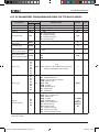
1
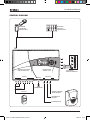
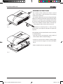
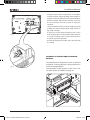
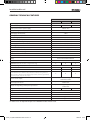
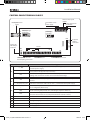
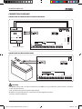
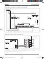
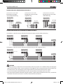
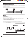
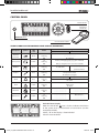
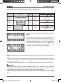
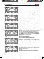
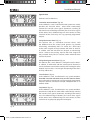
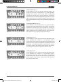
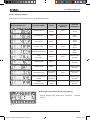
Burglar Alarm System
C4UC0201 - C4UC0401 - C4UC0801
Installation Manual
08-02-10/24800300
C4UC_Inst_EXPO 24800300 08-02-10.indd 1
08/02/10 10:49
Installation Manual
2
C4UC_Inst_EXPO 24800300 08-02-10.indd 2
08/02/10 10:49
Installation Manual
CONTENTS OF THE PACKAGE
In the control panel package you will find:
this manual, the control panel (according to the model purchased):
C4UC0201 + 4 electrical resistors of 1 kΩ 1/4W
C4UC0401 + 8 electrical resistors of 1 kΩ 1/4W
C4UC0801 + 16 electrical resistors of 1 kΩ 1/4W
A contact key, capable of generating a random variable code name with the to 16 million combinations.
The package does not include the battery or the cables for connection to electricity supply network.
m
SAFETY NOTES
m
• Carefully read the instructions before beginning
the installation and carry out the operations as
specified by the manufacturer.
• It is prohibited to use the product for purposes
other than those intended or for improper
purposes.
• It is prohibited to tamper with or modify the
product.
• If the labels are removed from the board the
warranty shall become invalid.
• Always use genuine spare parts.
• Installation, programming, operation and
maintenance of the product must be carried
out only by qualified and appropriately trained
technical staff in compliance with the regulations
in force. Security system installations are regulated
and permitted only to personnel with the
qualifications required by law, including accident
prevention observances.
• Operate in sufficiently well-lit environments that
meet health requirements and use instruments,
tools and equipment in good condition.
• At the end of the installation always check that the
equipment and the system as a whole are working
correctly.
• The electronic boards can be seriously damaged
by electrostatic charges: whenever they need to
be handled, wear suitable anti-static clothing and
footwear or, at least, make sure that you remove
any residual charge in advance by touching a
metal surface connected to the earthing system
(for example, the body of an electrical household
appliance) with your finger tips.
• For the 230V AC power supply it is essential to use
a double-insulated cable (with a double sheath), as
specified by the electrical safety standards.
• Use a wire terminal for connection to the 230V AC
- 50Hz network.
• Protect the equipment with an easily accessible
two-pole switch for cutting off the primary power
source. The distance between the contacts of this
cut-off device must be at least 3mm.
• Solder the joints between the wires in order to
avoid false alarms caused by rusting of the wires.
• Always remove the supply voltage before carrying
out any operation on the equipment.
• The electrical system must be conform to the
regulations in force in the country of installation.
• Use only shielded cables for connecting the devices
to the control panel.
• Do not install the control panel outside or in places
where it is subject to dripping or spraying of
water.
• Handle the control panel with care; it contains
electronic parts that are fragile and sensitive to
humidity.
• Only qualified personnel may replace the backup
battery. Disposal must be carried out in accordance
with the regulations in force. Use only sealed lead
batteries.
3
C4UC_Inst_EXPO 24800300 08-02-10.indd 3
08/02/10 10:49
Installation Manual
INDEX
Chapter
Page
GENERAL SYSTEM FEATURES
page
6
GENERAL DIAGRAM
page
7
ASSEMBLY INSTRUCTIONS
page 8
Assembly of the optional IR inserter BXINIR01. . . . . . . . . . . . . . . . . . . . . . . . . . . . . . . . . . . . . . . . . . . . . . . . . . . . . . . . . . . . . . . 9
GENERAL TECHNICAL FEATURES
page 10
CONTROL PANEL TERMINAL BLOCKS
page 11
CONNECTION DIAGRAMS
page 12
Connection to the electricity supply network. . . . . . . . . . . . . . . . . . . . . . . . . . . . . . . . . . . . . . . . . . . . . . . . . . . . . . . . . . . . . . . 12
Connection of the battery BB065. . . . . . . . . . . . . . . . . . . . . . . . . . . . . . . . . . . . . . . . . . . . . . . . . . . . . . . . . . . . . . . . . . . . . . . . . . . . 12
Example of connection of a siren to the Control Panel. . . . . . . . . . . . . . . . . . . . . . . . . . . . . . . . . . . . . . . . . . . . . . . . . . . . . . 13
Connection of the (optional) board C4MO04 . . . . . . . . . . . . . . . . . . . . . . . . . . . . . . . . . . . . . . . . . . . . . . . . . . . . . . . . . . . . . . . 13
Connection of a single sensor per input. . . . . . . . . . . . . . . . . . . . . . . . . . . . . . . . . . . . . . . . . . . . . . . . . . . . . . . . . . . . . . . . . . . . . 14
Connection of multiple sensors in series per input. . . . . . . . . . . . . . . . . . . . . . . . . . . . . . . . . . . . . . . . . . . . . . . . . . . . . . . . . 14
Connection of devices to the system bus . . . . . . . . . . . . . . . . . . . . . . . . . . . . . . . . . . . . . . . . . . . . . . . . . . . . . . . . . . . . . . . . . . . 15
Connection of the tamper contacts to the Control Panel terminal block. . . . . . . . . . . . . . . . . . . . . . . . . . . . . . . . . . . 15
CONTROL PANEL
page 16
Visual signals on the Control Panel display (upper part). . . . . . . . . . . . . . . . . . . . . . . . . . . . . . . . . . . . . . . . . . . . . . . . . . . . 16
Visual signals on the Control Panel display (lower part). . . . . . . . . . . . . . . . . . . . . . . . . . . . . . . . . . . . . . . . . . . . . . . . . . . . 17
INSTALLATION OF THE CONTROL PANEL
page 17
Procedure for accessing the programming phase (Technical Menu). . . . . . . . . . . . . . . . . . . . . . . . . . . . . . . . . . . . . . . 17
OPERATION OF THE DISPLAY IN THE TECHNICAL MENU
page 18
FUNCTIONS PROGRAMMABLE IN THE TECHNICAL MENU
page 19
Alarm timing. . . . . . . . . . . . . . . . . . . . . . . . . . . . . . . . . . . . . . . . . . . . . . . . . . . . . . . . . . . . . . . . . . . . . . . . . . . . . . . . . . . . . . . . . . . . . . . . 19
Alarm time. . . . . . . . . . . . . . . . . . . . . . . . . . . . . . . . . . . . . . . . . . . . . . . . . . . . . . . . . . . . . . . . . . . . . . . . . . . . . . . . . . . . . . . . . . . . . . . . . . 19
Entry time . . . . . . . . . . . . . . . . . . . . . . . . . . . . . . . . . . . . . . . . . . . . . . . . . . . . . . . . . . . . . . . . . . . . . . . . . . . . . . . . . . . . . . . . . . . . . . . . . . 19
Exit time. . . . . . . . . . . . . . . . . . . . . . . . . . . . . . . . . . . . . . . . . . . . . . . . . . . . . . . . . . . . . . . . . . . . . . . . . . . . . . . . . . . . . . . . . . . . . . . . . . . . 19
Balancing entries . . . . . . . . . . . . . . . . . . . . . . . . . . . . . . . . . . . . . . . . . . . . . . . . . . . . . . . . . . . . . . . . . . . . . . . . . . . . . . . . . . . . . . . . . . . 19
Balancing - Normally Closed. . . . . . . . . . . . . . . . . . . . . . . . . . . . . . . . . . . . . . . . . . . . . . . . . . . . . . . . . . . . . . . . . . . . . . . . . . . . . . . . 19
Balancing - Normally Open. . . . . . . . . . . . . . . . . . . . . . . . . . . . . . . . . . . . . . . . . . . . . . . . . . . . . . . . . . . . . . . . . . . . . . . . . . . . . . . . . 20
Single Balancing. . . . . . . . . . . . . . . . . . . . . . . . . . . . . . . . . . . . . . . . . . . . . . . . . . . . . . . . . . . . . . . . . . . . . . . . . . . . . . . . . . . . . . . . . . . . 20
Double Balancing. . . . . . . . . . . . . . . . . . . . . . . . . . . . . . . . . . . . . . . . . . . . . . . . . . . . . . . . . . . . . . . . . . . . . . . . . . . . . . . . . . . . . . . . . . . 20
4
C4UC_Inst_EXPO 24800300 08-02-10.indd 4
08/02/10 10:49
Installation Manual
Chapter
Page
Programmable automatic exclusion of the zones open at the moment of activation. . . . . . . . . . . . . . . . . . . . . .
Programmable Forced Arming. . . . . . . . . . . . . . . . . . . . . . . . . . . . . . . . . . . . . . . . . . . . . . . . . . . . . . . . . . . . . . . . . . . . . . . . . . . . . .
Automatic exclusion of all zones after a preset number of alarms. . . . . . . . . . . . . . . . . . . . . . . . . . . . . . . . . . . . . . . . . .
Status of the control panel when the power supply returns after a total power outage. . . . . . . . . . . . . . . . . . .
Assigning an area to the zones. . . . . . . . . . . . . . . . . . . . . . . . . . . . . . . . . . . . . . . . . . . . . . . . . . . . . . . . . . . . . . . . . . . . . . . . . . . . .
Permanent exclusion of a zone. . . . . . . . . . . . . . . . . . . . . . . . . . . . . . . . . . . . . . . . . . . . . . . . . . . . . . . . . . . . . . . . . . . . . . . . . . . . .
Type of zone. . . . . . . . . . . . . . . . . . . . . . . . . . . . . . . . . . . . . . . . . . . . . . . . . . . . . . . . . . . . . . . . . . . . . . . . . . . . . . . . . . . . . . . . . . . . . . . .
Immediate Intrusion Alarm . . . . . . . . . . . . . . . . . . . . . . . . . . . . . . . . . . . . . . . . . . . . . . . . . . . . . . . . . . . . . . . . . . . . . . . . . . . . . . . . .
Delayed Intrusion Alarm. . . . . . . . . . . . . . . . . . . . . . . . . . . . . . . . . . . . . . . . . . . . . . . . . . . . . . . . . . . . . . . . . . . . . . . . . . . . . . . . . . . .
Delayed Gong Intrusion Alarm. . . . . . . . . . . . . . . . . . . . . . . . . . . . . . . . . . . . . . . . . . . . . . . . . . . . . . . . . . . . . . . . . . . . . . . . . . . . . .
Assault Alarm. . . . . . . . . . . . . . . . . . . . . . . . . . . . . . . . . . . . . . . . . . . . . . . . . . . . . . . . . . . . . . . . . . . . . . . . . . . . . . . . . . . . . . . . . . . . . . .
Help Alarm . . . . . . . . . . . . . . . . . . . . . . . . . . . . . . . . . . . . . . . . . . . . . . . . . . . . . . . . . . . . . . . . . . . . . . . . . . . . . . . . . . . . . . . . . . . . . . . . .
Tamper alarm. . . . . . . . . . . . . . . . . . . . . . . . . . . . . . . . . . . . . . . . . . . . . . . . . . . . . . . . . . . . . . . . . . . . . . . . . . . . . . . . . . . . . . . . . . . . . . .
Technological Alarm. . . . . . . . . . . . . . . . . . . . . . . . . . . . . . . . . . . . . . . . . . . . . . . . . . . . . . . . . . . . . . . . . . . . . . . . . . . . . . . . . . . . . . . .
Impulse Key. . . . . . . . . . . . . . . . . . . . . . . . . . . . . . . . . . . . . . . . . . . . . . . . . . . . . . . . . . . . . . . . . . . . . . . . . . . . . . . . . . . . . . . . . . . . . . . . .
Stable Key . . . . . . . . . . . . . . . . . . . . . . . . . . . . . . . . . . . . . . . . . . . . . . . . . . . . . . . . . . . . . . . . . . . . . . . . . . . . . . . . . . . . . . . . . . . . . . . . . .
Events activating the outputs. . . . . . . . . . . . . . . . . . . . . . . . . . . . . . . . . . . . . . . . . . . . . . . . . . . . . . . . . . . . . . . . . . . . . . . . . . . . . . .
Resetting the Control Unit default programming . . . . . . . . . . . . . . . . . . . . . . . . . . . . . . . . . . . . . . . . . . . . . . . . . . . . . . . . . .
Detection of devices present on the BUS. . . . . . . . . . . . . . . . . . . . . . . . . . . . . . . . . . . . . . . . . . . . . . . . . . . . . . . . . . . . . . . . . . .
Procedure for exiting from the programming phase (Technical Menu). . . . . . . . . . . . . . . . . . . . . . . . . . . . . . . . . . . . .
LIST OF PARAMETERS PROGRAMMABLE FROM THE "TECHNICAL MENU"
21
21
22
22
22
22
23
23
23
23
23
23
24
24
24
24
25
25
26
26
page 27
5
C4UC_Inst_EXPO 24800300 08-02-10.indd 5
08/02/10 10:49
Installation Manual
GENERAL SYSTEM FEATURES
The C4UC0201/0401/0801 burglar alarm control panels meet the requirements of the following standards: CEI
79/2, CEI EN 50081-1 & EN 50130-4 and CEI EN 60950.
The control panel is equipped with 2 - 4 - 8 input zones (depending on the model) to which the magnetic
contacts, movement sensors or other types of intrusion sensors must be connected. The inputs can be
configured to work with single or double balancing or with NO or NC contact.
An additional zone, the 24H zone, is always active and must be used in order to prevent tampering with sirens,
diallers, sensors and the control panel itself.
This means that, even with the system disarmed, if the 24H zone detects an opening, the system will
automatically go into alarm due to tamper.
The H24 zone is disabled when the control panel is put into maintenance status.
The control panel has 2 Alarm Outputs, one "Control Panel Status" output, set up for connection of an optional
board for adding 4 outputs programmable as alarms:
Intrusion, Tamper, Help, Assault, Technological, Network Fault, Battery Fault, Generic Fault, System Partially
Armed, System Not Ready for Arming, System Disarmed.
The control panel can be completely configured and managed using the control keypad, the display and the
contact key inserter (with the corresponding key) located on the panel. It is, however, possible to connect
remote key inserters and keypads at appropriate points throughout the premises for ease of use. (The remote
keypads or inserters are not supplied as standard with the control panel and can be purchased at any time).
The 8-zone version of the Control Panel (C4UC0801) allows the Zones to be grouped into Areas (at most 4)
corresponding to the various system arming needs.
It is possible, for example, to associate the zones to which the perimeter sensors are connected to one area
and the volumetric sensors to another area.
The control panel can manage a maximum of 10 keys.
Whenever an optional keypad is used, users can use either a secret code for the keypad or an appropriately
programmed electronic key.
C4UC0201 Control Panel
It has 2 Zones or Inputs that are
shown in the lower part of the
display.
C4UC0401 Control Panel
It has 4 Zones or Inputs that are
shown in the lower part of the
display.
C4UC0801 Control Panel
It has 8 Zones or Inputs that are
shown in the lower part of the
display and can be grouped into
Areas (maximum 4).
.Note:
In this manual the display of the C4UC0801 Control Panel has been used in order to explain the programmable
features; where appropriate, the functions that can be performed from the different versions will be pointed out.
6
C4UC_Inst_EXPO 24800300 08-02-10.indd 6
08/02/10 10:49
Installation Manual
GENERAL DIAGRAM
MAXIMUM
MASSIMO 4
4INSERITORI
INSERTERS
CONNECTABLE
COLLEGABILI
MAXIMUM
MASSIMO 4
4TASTIERE
KEYPADS
CONNECTABLE
COLLEGABILI
Linea
Bus
NA
C
NC
NA
C
NC
NA
C
NC
NA
C
NC
Inseritore
opzionale
OPTIONAL
INSERTER
chiave a Infrarosso
FORper
INFRARED
KEY
Inseritore
per
INSERTER
FOR
chiave a contatto
CONTACT
KEY
INPUTS
INGRESSI
1
2
3
4
5
TAMPER
6
7
4 MODULO
OPTIONAL
4 USCITE
OUTPUTSOPZIONALI
MODULE
OUTPUTS
USCITE
8
C4UC0201
C4UC0401
C4UC0801
TAMPER 24h
ARMED
CONTROL
USCITA CENTRALE
INSERITA
(+PCS/+MCS)
PANEL
OUTPUT
ALARM
RELAY
USCITA RELÈ
ALLARME
NC - C - NA
OUTPUT
ALARM
OUTPUT
USCITA ALLARME
(+PCA/+MCA)
7
C4UC_Inst_EXPO 24800300 08-02-10.indd 7
08/02/10 10:49
Installation Manual
ASSEMBLY INSTRUCTIONS
The assembly of the control panel must be carried
out in a zone that is easily accessible at least during
maintenance operations.
To meet this requirement, a free zone of approximately
500 mm must be left around the entire perimeter of the
container so as to allow easy mounting and removal of
the cover, to allow maintenance technicians to operate
easily and to facilitate network cables and those for
connecting the other devices to be be passed.
fig. 1
Position the control panel in a clean and dry
location that is not subject to vibrations or impacts of
any kind.
The installation of the Control Panel must be carried out
as described below:
• open the cover by unscrewing the screw positioned
on the bottom of the Control Panel (fig. 1).
• detach the cover from the container exerting slight
pressure on the side "tongues" as shown in the figure
(fig. 1).
• lift the Control Panel cover upwards (fig. 2).
fig. 2
8
C4UC_Inst_EXPO 24800300 08-02-10.indd 8
08/02/10 10:49
Installation Manual
fig. 3
• using the bottom of the Control panel as a template,
mark the position of holes for fixing shown in figure 3,
making sure that the wall is flat at the selected position;
• drill the wall that will hold the container and insert
the screw anchors necessary in order to secure the
container;
• secure the bottom of the container solidly to the wall
making sure that the tamper-proof switch (shown in
fig. 4) trips correctly.
• In order to pass the cables through you can use the
holes for this purpose on the bottom of the container
or (using a hacksaw) open up the preformed slit in
the upper part of the container.
• Position the battery in its holder and to proceed with
the wiring.
ASSEMBLY OF THE OPTIONAL IR INSERTER
BXINIR01
fig. 4
The control panel is designed to contain an optional
inserter for an infrared key that is to be positioned as
shown in the figure below.
The connection of the terminals is the same as for
any other device on the BUS (see page 15).
9
C4UC_Inst_EXPO 24800300 08-02-10.indd 9
08/02/10 10:49
Installation Manual
GENERAL TECHNICAL FEATURES
CONTROL PANEL TYPE
C4UC0201
Power supply:
Maximum absorption:
C4UC0401
120mA
140mA
Battery recharge current (max):
400 mA
Load supply current (max):
0.85 A
Primary transformer protection:
PTC
Battery charger protection:
Fuse F1: (T1A, 250 V)
Alarm device output protection:
300mA Resettable fuse
Control Panel status signal output protection:
100mA Resettable fuse
Load supply protection:
Fuse F2: (T1A, 250 V)
Operating temperature:
5 ÷ 40 °C
sealed lead 12 V 7 Ah (model BB065)
Dimensions ( L x H x D mm):
350 x 230 x 85
Weight without battery (kg):
2,5
Container material:
ABS
Protection Grade:
IP 30
Safety
device with double insulation
Safety Level CEI 79-2:
Input zones (NC, NO, double or single balancing.)
150mA
1.0A
14V DC ±2%
Control panel internal power supply
Batteries installable (max):
C4UC0801
230V AC ± 10% 50Hz
2°
2
Anti-tampering zone (24h)
4
8
1
Divisible zones
2
4
-
Divisible areas
-
-
4
Zones programmable as:
"Immediate Intrusion Alarm”, “Delayed Intrusion Alarm”, “Gong Intrusion
Alarm”, “Tamper alarm”, “Assault Alarm”, “Help Alarm”, “Technological Alarm”,
“Stable Key Input”, “Impulse Key Input”.
2
4
8
Generic alarm output:
Alarm output for sirens:
Outputs for signalling control panel operational
Programmable Open Collector Outputs *
switch contact of the alarm relay without voltage
max 5A at 30V DC
output with voltage without alarm 13.8 V DC
300mA max
output with voltage in operation 13.8 V DC
100mA max
4
4
Programmable Alarm Time
YES from 20 to 600 seconds
Input Alarm Time
YES from 1 to 120 seconds
Output Alarm Time
YES from 1 to 120 seconds
Automatic Exclusion of an Open Zone
YES Programmable
Automatic Exclusion of a Zone in Alarm
YES Programmable
4
* In order to use the Optional Outputs the C4MO0401 module must be used
10
C4UC_Inst_EXPO 24800300 08-02-10.indd 10
08/02/10 10:49
Installation Manual
CONTROL PANEL TERMINAL BLOCKS
System
BUS and its
BUS di sistema
power
supply
e relativa
alimentazione
BUS
Jumper for
Ponticello
24h
Tamper
per l’esclusione
exclusion
del Tamper 24h
F2
CN3
M2
C4UC0201
+
–
Z1
C
Z2
Z3
C
Z4
+
–
Z5
C
Z6
Z7
Collegamento
Sensor
connection
Sensori
Terminals
–, +, BUS
MCS
PCS
~
24h
+, –, Z1, C, Z2, Z3, C, Z4,
+, –, Z5, C, Z6, Z7, C, Z8
NC, NO, C,
–
M3
CN4
C4UC0401
OFF
24h
Collegamento
Control
panel dispositivo
antimanomissioneconnection
di Centrale
anti-tampering
M2
M1
C4UC0801
24h
M1
+ MCS PCS
Protezione
Load
supply
alimentazione carichi
protection
F1
–BAT
–
MCA
PCA
Z8
NC NA
C MCA PCA
GND
RXD
TXD
+5V
4
optional
Connessione
outputs
4 uscite
connection
opzionali
CN2
–
Collegamento
Alarm
devices connection
dispositivi di Allarme
Meaning
Terminals for connecting inserters (maximum 4) and keypads (maximum 4)
and related power supply.
Terminal with a voltage of 14 V DC which disappears when the control panel is put into
service; works in the opposite way to the PCS;
Terminal with a voltage of 14 V DC when the control panel is in service; it is used for
resetting sirens and sensors and for connection with radio bridges;
Low voltage input from the transformer secondary
Connection of the anti-tampering zone always active even with the control panel
disarmed
Terminals for connection of the sensors and +, – terminals for their power supply
This is a switch relay without voltage that switches in the case of alarm. The activation
time is configurable (Alarm time).
Terminal with a voltage of 14 V DC which disappears with the control panel in alarm; to be
used for connecting self-powered sirens, radio bridges, telephone diallers etc..;
Terminal with a voltage of 14 V DC when the control panel is in alarm; to be used for the
connection of sirens that are not self-powered from the outside or inside;
Connection to RS232 interface
Connection for module with 4 optional C4MO0401 outputs
CN2
CN4
OFF
24h
F1
BXRS23
AUX OUTPUTS
FUSE
Battery charger protection fuse
F2
FUSE
Load supply protection fuse
TAMPER
C
M3
GND
OUT4
OUT3
OUT2
OUT1
+
AUX OUTPUTS
+BAT
Battery
charger
Protezione
protection
carica batteria
BXRS23
Battery
connection
Faston
faston
collegamento
Batteria
Armed control panel
outputs
Uscite Centrale Inserita
PowerAlimentazione
supply from
da trasformatore
transformer
Housing for the jumper for exclusion of the TAMPER 24h
11
C4UC_Inst_EXPO 24800300 08-02-10.indd 11
08/02/10 10:49
Installation Manual
CONNECTION DIAGRAMS
CONNECTION TO THE ELECTRICITY SUPPLY NETWORK
M1
BUS
+BAT
F2
230Vca
CN4
C4UC0801
CN3
C4UC0401
OFF
24h
C4UC0201
24h
+
–
Z1
C
M2
Z2
Z3
C
Z4
+
–
Z5
C
Z6
Z7
C
M3
Z8
NC NA
C MCA PCA
GND
OUT4
OUT3
OUT2
OUT1
+
AUX OUTPUTS
F1
–BAT
+ MCS PCS
GND
RXD
TXD
+5V
BXRS23
18Vca
–
CN2
–
Mains
power di
supply
Alimentazione
rete
230Vca - 50Hz
CONNECTION OF THE BATTERY BB065
M1
BUS
F1
–BAT
–
+ MCS PCS
F2
CN4
C4UC0801
CN3
C4UC0401
OFF
24h
C4UC0201
24h
+
–
Z1
C
M2
Z2
Z3
C
Z4
+
–
Z5
C
Z6
Z7
C
Z8
M3
NC NA
C MCA PCA
–
WARNING
• The BB065 battery, with a maximum external load of 200mA, can guarantee the system 24 hours' autonomy
in the absence of power.
• Only qualified personnel may replace the batteries.
• Batteries must be disposed of in accordance with the regulations in force.
• Use only sealed lead batteries.
12
C4UC_Inst_EXPO 24800300 08-02-10.indd 12
08/02/10 10:49
GND
OUT4
OUT3
OUT2
OUT1
+
AUX OUTPUTS
+BAT
GND
RXD
TXD
+5V
BXRS23
–
+
CN2
Installation Manual
EXAMPLE OF CONNECTION OF A SIREN TO THE CONTROL PANEL
– 12Vcc MCA PCS
MANS
Siren
terminaldella
block
Morsettiera
Sirena
BRAHMS SA10L
M1
BUS
F2
CN4
C4UC0801
CN3
C4UC0401
C4UC0201
OFF
24h
24h
+
–
+ MCS PCS
Z1
C
M3
M2
Z2
Z3
C
Z4
+
–
Z5
C
Z6
Z7
C
Z8
NC NA
C MCA PCA
GND
OUT4
OUT3
OUT2
OUT1
+
AUX OUTPUTS
F1
–BAT
–
GND
RXD
TXD
+5V
BXRS23
+BAT
CN2
–
CONNECTION OF THE (OPTIONAL) BOARD C4MO0401
+
Power
supply source
Sorgente
di alimentazione
NA
M1
BUS
–
C
NC
+ MCS PCS
NA
C
NC
NA
F2
M2
Z4
+
–
Z5
C
M3
GND
OUT4
OUT3
OUT2
OUT1
+
AUX OUTPUTS
CN3
NC
GND
RXD
TXD
+5V
BXRS23
C4UC0801
C
C
CN4
NA
C
NC
CN2
Z7 Cimage
Z8
NCillustrates
NA C MCA PCA an
–
This
example of a possible connection of the loads to the 4 relay outputs of the output
module in NO mode; it is of course also possible to choose the NC connection mode.
The capacity of the relay contacts is 1 A, 12 – 24 V DC.
Z6
13
C4UC_Inst_EXPO 24800300 08-02-10.indd 13
08/02/10 10:49
Installation Manual
CONNECTION OF A SINGLE SENSOR PER INPUT
Connection for sensors with
Normally Closed or Open
contacts without balancing
Connection for sensors with
Normally Closed contacts with
single balancing
Connection for sensors with
Normally Closed contacts with
double balancing
Generic terminal
Morsettiera
generica di
blockunfor
a sensor
sensore
Generic terminal
Morsettiera
generica di
blockunfor
a sensor
sensore
Generic terminal
Morsettiera
generica di
blockunfor
a sensor
sensore
TAMPER
ALARM
TAMPER
ALLARME
+
TAMPER
ALARM
TAMPER
ALLARME
+
TAMPER
ALARM
TAMPER
ALLARME
+
–
–
RFL= 1000Ω
Control
Panel
Morsettiera
Terminal
Centrale Block
Control
Panel
Morsettiera
Terminal
CentraleBlock
–
–
+
RFL
RFL= 1000Ω
RA = 1000Ω
Control
Panel
Morsettiera
Terminal
Block
Centrale
–
+
–
RFL RA
+
Z1
Z1
Z1
C
C
C
CONNECTION OF MULTIPLE SENSORS IN SERIES PER INPUT
Connection in series for sensors with Normally Closed or Open contacts without balancing
Generic
Morsettieraterminal
generica di
blockunfor
a sensor
sensore
TAMPER
ALARM
TAMPER ALLARME +
Generic terminal
Morsettiera
generica di
blockunfor
a sensor
sensore
TAMPER
–
ALARM
TAMPER ALLARME +
–
Generic
Morsettieraterminal
generica di
blockunfor
a sensor
sensore
TAMPER
ALARM
TAMPER
ALLARME
+
–
Control
Panel
Morsettiera
Terminal
Block
Centrale
–
+
Z1
C
Connection in series for sensors with Normally Closed contacts with single balancing
Generic
Morsettieraterminal
generica di
blockunfor
a sensor
sensore
TAMPER
ALARM
TAMPER
ALLARME
+
–
RFL= 1000Ω
Generic terminal
Morsettiera
generica di
blockunfor
a sensor
sensore
Generic
Morsettieraterminal
generica di
blockunfor
a sensor
sensore
TAMPER
ALARM
TAMPER
ALLARME
+
TAMPER
ALARM
TAMPER
ALLARME
+
–
–
Control
Panel
Morsettiera
Terminal
Block
Centrale
–
RFL
+
Z1
C
WARNING
• Connect the sensors to the terminals of the control panel only by means of a shielded cable, connecting the
sleeves of the shields of the various conductor ends together; lastly, connect the sleeve of the shield only
from the central side, connecting it to the negative terminal of the control board power supply.
• In case of connection with double balancing it is not possible to connect the sensors in series.
• The previously illustrated connection diagrams refer to a generic terminal block for the sensors: consult the
instruction manual for each sensor in order to make the exact connections.
14
C4UC_Inst_EXPO 24800300 08-02-10.indd 14
08/02/10 10:49
Installation Manual
CONNECTION OF DEVICES TO THE SYSTEM BUS
As an example, a connection diagram is included for keypads (maximum 4) or inserters (maximum 4) that can
be connected on the system bus.
Keypad
Morsettiera
Terminal
Block
Tastiera
–
+
Inserter
Morsettiera
Terminal
Block
Inseritore
BUS
–
+
BUS
Control
Panel
Morsettiera
Terminal
CentraleBlock
BUS
+
–
WARNING
• The devices located along the system bus must be connected strictly in parallel with each other (with an “in
and out” connection).
• Connect the serial communication line only with twisted cable (twisted pair).
• The maximum overall wiring length is 100m.
• The cross-section of the power supply cables of the devices on the bus must be at least 2 x 0,5 mm2.
• It is not recommended to connect the bus with shunting: where the topology of the system does not allow
a rectilinear connection between the various devices.
CONNECTION OF THE TAMPER CONTACTS TO THE CONTROL PANEL TERMINAL BLOCK
Connection to other Tamper
Collegamento verso altri
contacts of the system
contatti Tamper dell’impianto
BUS
+BAT
F1
–BAT
Anti-opening
Tamper
tamper
antiapertura
–
F2
Anti-removal
Tamper
tamper
antirimozione
C4UC0801
C
C4UC0401
Control
panel
tamper
Contatti
Tamper
contacts
OFF
24h
C4UC0201
24h
+
–
Z1
C
M3
M2
Z2
Z3
C
Z4
+
–
Z5
C
Z6
Z7
C
Z8
NC NA
C MCA PCA
della centrale
15
C4UC_Inst_EXPO 24800300 08-02-10.indd 15
+ MCS
08/02/10 10:49
–
Installation Manual
CONTROL PANEL
CONTROL KEYPAD
INSERTER FOR
CONTACT KEY
RECEIVER FOR
OPTIONAL IR INSERTER
KEY FOR CONTACT INSERTER
VISUAL SIGNALS ON THE CONTROL PANEL DISPLAY (UPPER PART)
Meaning
LED
colour
Status
Network
presence
Green
Lit
Flashing
Off
230 V AC present
--------------No network
Battery status
Yellow
Lit
Flashing
Off
Battery run down (in the case of no network)
--------------Battery charged (in the case of no network)
ON/OFF
Green
Lit
Flashing
Off
Tamper
Red
Lit
Flashing
Off
Alarm
Red
Lit
Flashing
Off
Fault
Yellow
Lit
Flashing
Off
Exclusion
Yellow
Lit
Flashing
Off
At least one zone excluded
-----------------------------
-------------------------------------------
Maintenance
Yellow
Lit
Flashing
Off
-------------------------------------------
Maintenance
-----------------------------
Description
Symbol
Control Panel ON
system armed
In / Out time
--------------
Control Panel OFF
--------------------------system disarmed
Tamper in progress
Tamper alarm saved
No tamper in progress
Alarm in progress
System Not Ready
Alarm Saved
No alarm
Generic fault (fuse F2 / external bus)
Fault saved
No Fault
Excluded Zones Display
When the LED of the
icon is lit, this indicates the division
of the system, that is, the exclusion of some zones (see the
example to the left).
LED lit + "E" on the display = Zone Excluded
LED off = Zone Included
16
C4UC_Inst_EXPO 24800300 08-02-10.indd 16
08/02/10 10:49
Installation Manual
VISUAL SIGNALS ON THE CONTROL PANEL DISPLAY (LOWER PART)
Description
Symbol
Exclusion
Status of the
zones
Meaning
LED
colour
Status
Red
Lit
Flashing
Off
Lit
Burglar
Alarm
Red
Flashing
Off
Tamper
Alarm
Red
Flashing
Off
Lit
Control Panel ON
Control Panel
OFF
Zone excluded
---------Zone Included
Zone in alarm
Zone not ready
Alarm Saved
Zone idle
Zone in alarm
Zone not ready
Alarm Saved
Zone idle
INSTALLATION OF THE CONTROL PANEL
Procedure for accessing the programming phase (Technical
Menu).
fig. 1
Connect the control panel to the electricity supply network;
make sure that the “Network Presence" indicator is lit (fig. 1).
Insert the supplied key (which must be the first recognised
by the control panel) into the inserter, press the lp buttons
simultaneously; when the indicator above the
icon lights
up and the first programmable parameters appear (fig. 2) this
indicates that you have entered the "Technical Menu".
fig. 2
Notes:
• When the Control Panel is in the "Technical Menu", the extraction or the insertion of the key does not produce any
effect.
• With the factory settings the "h24" anti-tampering zone is disabled by a jumper called "OFF h24" placed next to the
"h24" terminal (see page 11), which allows all the setting up operations to be carried out and prevents accidental
activation of the alarm relay.
• During Maintenance/Programming (that is, in "Technical Menu" mode) the alarm relay is in any case disabled.
WARNING
• If you have chosen to install the optional BXINIR01 inserter on the Control Panel and therefore to
manage the Control Panel by means of the infrared key, it is important to always safeguard the contact
key supplied, since is the only one that will allow access to the “Technical Menu”.
• Before closing the control panel remove the "OFF 24H" jumper in order to re-enable the anti-tampering
zone.
17
C4UC_Inst_EXPO 24800300 08-02-10.indd 17
08/02/10 10:49
Installation Manual
OPERATION OF THE DISPLAY IN THE TECHNICAL MENU
1
The qp pushbuttons allow
you to scroll through the
possible parameters to be
changed.
2
Once the desired parameter
is displayed, when you press
the l pushbutton the value
that can be changed will
begin to flash.
3
The q p pushbuttons
are used to select the
options associated with the
highlighted field or to modify
the values that it contains.
4
By
pressing
the
l
pushbutton, the value
or choice set will change
its status from flashing to
constant, confirming that the data has been
saved.
5
When the section to be
modified contains several
modifiable
parameters,
pressing the l pushbutton,
in addition to confirming the
data entered, also allows access to the modification
of the next parameter.
6
At this point proceed as
specified in points 3 and 4.
All the data entered will
become operational when
you exit from the "Technical
Menu".
WARNING
• Should it be necessary to abandon the data entry procedure in progress, just press the t pushbutton to
return to the previous window.
• If no pushbutton has been pressed before 1 minute elapses, the Control Panel will automatically exit
from the "Technical Menu" and the data entered will not be saved.
18
C4UC_Inst_EXPO 24800300 08-02-10.indd 18
08/02/10 10:49
Installation Manual
FUNCTIONS PROGRAMMABLE IN THE TECHNICAL MENU
Alarm timing
Alarm time (fig. 3)
This is the duration (expressed in seconds) of siren activation
in the case of intrusion/tamper alarms. It is also the activation
duration for the outputs activated by “Alarm” events.
fig. 3
Entry time (fig. 4)
This is the time (expressed in seconds) that the control panel
waits from the moment that the disarming procedure starts
in order to consider any unbalanced (in alarm) zones defined
as “Delayed Anti-Intrusion” or “Gong Anti-intrusion”. It is the
time that allows the user to enter the protected premises and
deactivate the control panel. It is not taken into account for
zones defined as “Immediate Anti-intrusion”.
fig. 4
fig. 5
Contatto
di allarme
Z1
Z1
Condizione di riposo
ingresso aperto
Exit time (fig. 5)
This is the time (expressed in seconds) that the control panel
waits from the moment that the arming procedure starts in order
to consider any unbalanced (in alarm) zones defined as “Delayed
Anti-Intrusion” or “Gong Anti-intrusion”. It is the time that allows
the user to leave the protected premises after activating the
control panel. It is not taken into account for zones defined as
“Immediate Anti-intrusion”.
Notes:
• During the "Entry Time" and "Exit Time" the buzzers of the keypad
Contatto
Contatto
Contatto
di allarme
di allarme
allarme
(optional) and the control
panel will sound and thedi LED
will
flash to signal imminent
activation.
Z1
Z1
Balancing inputs
Condizione di allarme
ingresso chiuso a massa
Taglio della linea
non rilevato
Cortocircuito sulla linea
come ingresso
For all inputs (or zones) you must indicate chiuso
the type
of physical
a massa
connection from the sensors to the terminals of the control
panel.
The types of balancing can be:
Balancing - Normally Closed (fig. 6)
fig. 6
Alarm
Contatto
dicontact
allarme
Alarm
Contatto
dicontact
allarme
Z1
Z1
Resting conditions
Condizione
di riposo
input
closed
andaearthed
ingresso
chiuso
massa
Alarm
Contatto
dicontact
allarme
Z1
Alarm condition
Condizione
di allarme
input open
ingresso
aperto
Alarm
Contatto
dicontact
allarme
Z1
Line
cutlinea
Taglio
della
asingresso
open input
come
aperto
Line cut
Cortocircuito
sulla linea
as open
input
NON
RILEVATO
19
C4UC_Inst_EXPO 24800300
08-02-10.indd 19
Contatto
di allarme
Contatto
di allarme
Contatto
di allarme
Contatto
di allarme
08/02/10 10:49
Installation Manual
Contatto
di allarme
Contatto
di allarme
Z1
Z1
Contatto
Condizione didi
riposo
allarme
ingresso aperto
Contatto
Condizione di
allarme
di allarme
ingresso chiuso a massa
Condizione di
riposo
Alarm
Contatto
dicontact
allarme
ingresso aperto
Condizione di
allarme
Alarm
Contatto
dicontact
allarme
ingresso chiuso
a massa
Contatto
di allarme
Resting conditions
Condizione
di
riposo
input open
ingresso
aperto
Z1
Contatto
Condizione di
riposo
di allarme
ingresso chiuso
a massa
Contatto
Z1
Condizione diContatto
allarme
di allarme
ingresso aperto
Alarm
Contatto
dicontact
allarme
Resting conditions
Contatto
Condizione
di
riposo
di allarme
ingressoterminal
chiuso
ablock
massa
Generic
for
con aresistenza
RFL=1KΩ
sensor
RFL
= 1K
Z1
Condizione di
riposo
Contatto
di allarme
ingresso chiuso
a massa
con resistenza RFL=1KΩ
Alarm
Contatto
dicontact
allarme
Condizione di allarme
ingresso
Z1 aperto
Contatto
Taglio della
linea
di allarme
come ingresso
aperto
Alarm condition
Condizione
diContatto
allarme
di allarme
ingresso
aperto
input open
Taglio della
linea
Contatto
di allarme
come ingresso
aperto
Condizione di riposo
Z1
ingresso
chiuso
aRFLmassa
RA
fig.
con9 resistenza RFL=1KΩ
Condizione
Alarm di riposo
Tamper
Contatto
Contatto
contact
dicontact
tamper
allarme a massa
ingressodichiuso
con resistenza RFL=1KΩ
Resting conditions
Condizione
di riposo
Contatto
Contatto
Generic
block
for
ingressoterminal
massa
di tamper
dichiuso
allarme a
con aresistenza
sensor RFLRFL=1KΩ
= 1K
cut
Contatto
TaglioLine
della
linea
input aperto
opendi >allarme
alarm
ingresso
allarme
Z1
RFL
Alarm condition
Condizione
di allarme
Contatto
Contatto
Generic
terminal
for a
ingresso
a massa
di tamper
di chiuso
allarme block
con sensor
resistenza
RFL+RA
= 2KΩ
RFL+RA
= 2K
Z1
RA
RFL
Condizione di allarme
ingresso chiuso a massa
con resistenza RFL+RA = 2KΩ
C4UC_Inst_EXPO 24800300 08-02-10.indd 20
Short circuit on
thelinea
line
Contatto
Cortocircuito
sulla
as
input closed
earthed
Ingresso
chiusodiand
aallarme
massa
Allarme
manomissione
> Tampering
alarm
RA
RFL
Line
cutlinea
Taglio
della
Contatto
Contatto
input
open
ingresso
aperto> di tamper
di allarme
Tampering
alarm
Allarme
Manomissione
Z1
RA
Cortocircuito Contatto
sulla linea
Ingresso chiusodi aallarme
massa
Allarme manomissione
Z1
TaglioContatto
della linea
Alarm
Tamper
Contatto
tamper
dicontact
allarme
ingresso
aperto dicontact
Allarme Manomissione
Z1
RFL
RFL
Contatto
di tamper
Contatto
di allarme
Condizione di allarme
Taglio
della linea
Double Balancing
Z1
Z1 (fig. 9)
ingresso
aperto
ingresso
aperto
allarme
RFL
RFL
RA
RA
RA
RFL
Z1
Taglio della
linea
Contatto
di allarme
ingresso aperto
allarme
RFL
Contatto
di tamper
Condizione
Alarm di allarme
Tamper
Contatto
Contatto
dicontact
tamper
allarme a massa
ingressodicontact
chiuso
con resistenza RFL+RA = 2KΩ
Contatto
di allarme
Cortocircuito sulla linea
NON RILEVATO
Z1
RFL
Z1
Contatto
di allarme
Z1
Cortocircuito Contatto
sulla linea
di allarme
NON RILEVATO
RFL
Z1
Condizione di
allarme
Contatto
allarme
ingresso diaperto
RFL
20 Condizione di riposo
ingresso chiuso a massa
con resistenza RFL=1KΩ
Alarm
Contatto
dicontact
allarme
RFL
RFL
Cortocircuito Contatto
sulla linea
di allarme
NON RILEVATO
Z1
Taglio della linea
come ingresso
aperto
Z1
Z1
RFL
Contatto
di tamper
Contatto
di allarme
Short circuit on
thelinea
line
Cortocircuito
sulla
as input
closed
and earthed
come
ingresso
chiusoZ1a massa
Z1
RFL
Z1
Contatto
di allarme
Cortocircuito Contatto
sulla
Alarm linea
dicontact
allarme
come ingresso
chiuso a massa
Z1
RFL
RA
Z1
Single Balancing (fig. 8)
RFL
Z1
Contatto
Z1
Condizione di riposo
ingresso chiuso
a massa
Z1
Z1
Z1
Condizione di
allarme
Contatto
allarme
ingresso diaperto
Z1
Contattolinea
Cortocircuito disulla
allarme
come ingresso
chiuso a massa
Z1
di allarme
cut
TaglioLine
della
linea
NOT
nonDETECTED
rilevato
Z1
Condizione di
riposo
Contatto
di allarme
ingresso chiuso
a massa
RA
Taglio della
linea
Alarm
Contatto
dicontact
allarme
non rilevato
Z1
allarme
Alarm condition
Condizione
didi allarme
input closed
and
ingresso
chiuso
a earthed
massa
Z1
Z1
Contatto
Taglio della
linea
di allarme
non rilevato
Z1
Z1
Z1
Balancing - Normally Z1Open (fig. 7)
Z1
Z1
Contatto
di allarme
Z1
fig. 7
fig. 8
Contatto
di allarme
RFL
Taglio della linea
ingresso aperto
Allarme Manomissione
RFL
Contatto
di tamper
Contatto
di allarme
Cortocircuito sulla linea
Z1
Ingresso
chiuso
a RFL
massa
RA
Allarme manomissione
Cortocircuito
linea
Alarm sulla Contatto
Tamper
Contatto
dicontact
tamper
dicontact
allarme a massa
Ingresso chiuso
Allarme Manomissione
Z1
RA
RFL
Short circuit on
thelinea
line
Cortocircuito
sulla
Contatto
Contatto
as
input closed
earthed
Ingresso
chiuso
a massa
di tamper
di allarmeand
> Tampering
alarm
Allarme
Manomissione
Z1
RA
RFL
Cortocircuito sulla linea
Ingresso chiuso a massa
Allarme Manomissione
08/02/10 10:49
Installation Manual
Programmable automatic exclusion of the zones open at
the moment of activation.
fig. 10
This option lets you determine the behaviour of the control
panel whenever, on partial or total arming of the system, one or
more zones that should be armed (defined as “Immediate Antiintrusion” or “Delayed Anti-intrusion” or “Gong Anti-intrusion”)
are already in alarm status.
If the pre-selected value is “YES” (fig. 10), such zones are
automatically disabled by the control panel until the next time
that the zone in question is switched off.
If the pre-selected value is “NO” (fig. 11), the behaviour of the
control panel is determined by the pre-selected value for the
parameter “Forced Arming”.
fig. 11
Programmable Force Arming.
fig. 12
fig. 13
If theAutomatic Exclusion of such zones has been deactivated
(see above), this option determines the behaviour of the control
panel whenever, on partial or total arming of the system, one or
more zones that should be armed (defined as “Immediate Antiintrusion” or “Delayed Anti-intrusion” or “Gong Anti-intrusion”)
are already in alarm status.
If the pre-selected value is “YES” (fig. 12), the user has the
possibility to decide whether to proceed in any case with system
arming: the zones in alarm status will be automatically excluded
by the control panel until the next time that the system/area is
switched off.
If the pre-selected value is “NO” (fig. 13), forced arming is not
possible.
21
C4UC_Inst_EXPO 24800300 08-02-10.indd 21
08/02/10 10:49
Installation Manual
Automatic exclusion of all zones after a preset number of
alarms.
fig. 14
fig. 15
fig. 16
This option lets you determine the behaviour of the control panel
when the same zone (defined as “Immediate Anti-intrusion” or
“Delayed Anti-intrusion” or “Gong Anti-intrusion”) generates more
than one alarm in a single arming/disarming cycle.
The numeric value inserted (fig. 14) establishes after how many
alarms the zone should be excluded until the next time that
the same zone is switched off, in order to avoid it generating
further alarms.
In the case of the “Tamper” zone present on the board of the
control panel or of a zone defined as “Anti-assault”, “Help”,
“Tamper” or “Technological”, alarms are counted even with the
control panel disarmed; therefore in order to reset the number
of alarms to zero you need to perform an alarm reset (page 7 of
the "User Manual").
If the value of the parameter is set to 0, the zones will never
be disabled.
Status of the control panel when the power supply returns
after a total power outage.
This option lets you determine the behaviour of the control
panel when the power supply returns after a total outage.
You can decide that the control panel will arm all the zones (fig.
15) or will disarm them (fig. 16) or that, on restart, the previous
arming state will be restored (fig. 17).
fig. 17
Assigning an area to the zones
(Function active only for the C4UC0801 model)
Each zone can be assigned to one of the 4 available division
areas (fig. 18).
It is always possible to arm or disarm individual “areas” from the
control panel or from optional inserters and keypads.
fig. 18
Permanent exclusion of a zone.
Each zone can be disabled in a permanent manner.
This function is particularly useful if a sensor suffers faults that
provoke false alarms (fig. 19).
.Note:
The LED of the excluded Zone will remain permanently lit.
fig. 19
22
C4UC_Inst_EXPO 24800300 08-02-10.indd 22
08/02/10 10:49
Installation Manual
Type of zone.
Each zone can be defined as:
fig. 20
fig. 21
fig. 22
“Immediate Intrusion Alarm” (fig. 20)
A zone defined as such, if unbalanced with system/area armed,
provokes the “Intrusion Alarm” event which automatically
activates the acoustic alarm signals (continuous sounding of
the central unit and the keypad buzzer), the visual alarm signals
(of the central unit, additional keypads and inserters) and the
activation of the alarm relay and any purposely programmed
outputs.
“Delayed Intrusion Alarm” (fig. 21)
This behaves like an "Immediate Intrusion Alarm", with
the difference that the control panel ignores any possible
unbalancing, immediately after it is armed, for a time equal
to the value assigned to the parameter “Exit Time” in seconds.
In addition, once the “Exit Time” has elapsed, its unbalancing
causes a time to start running, equal to the value assigned to
the parameter “Entry Time” in seconds, within which the zone
must be disarmed.
“Delayed Gong Intrusion Alarm” (fig. 22)
This behaves like a zone defined as “Delayed Intrusion Alarm”.
In addition, if unbalanced with the control panel disarmed, it
causes the buzzer sound of the control panel and keypads to be
emitted. (can be used as a warning for the opening of the doors
of shops, offices etc.)
“Assault Alarm” (fig. 23)
A zone defined as such, if unbalanced in any system condition,
does NOT cause the activation of any visual or acoustic alarms
but can be used to activate one or more purposely programmed
outputs in order to activate, for example, a telephone call via an
external dialler.
fig. 23
“Help Alarm” (fig. 24)
A zone defined as such, if unbalanced in any system condition,
provokes the “Help Alarm” event which automatically activates
the acoustic alarm signals (continuous sounding of the central
unit and additional keypad buzzers), the visual alarm signals
(of the central unit, additional keypads and inserters) and the
activation of any purposely programmed outputs.
fig. 24
23
C4UC_Inst_EXPO 24800300 08-02-10.indd 23
08/02/10 10:49
Installation Manual
fig. 25
fig. 26
fig. 27
fig. 28
“Tamper alarm” (fig. 25)
A zone defined as such (also like the dedicated zone on the
control panel board), if unbalanced in any system condition,
provokes the “Tamper alarm” event which automatically
activates the acoustic alarm signals (continuous sounding of
the central unit and additional keypad buzzer), the visual alarm
signals (of the central unit, additional keypads and inserters) and
the activation of the alarm relay and any purposely programmed
outputs.
“Technological Alarm” (fig. 26)
A zone defined as such, if unbalanced in any system condition,
provokes the “Technological Alarm” event which automatically
activates the acoustic alarm signals (continuous sounding of
the central unit and additional keypad buzzers), the visual alarm
signals (of the central unit, additional keypads and inserters) and
the activation of any purposely programmed outputs.
“Impulse Key” (fig. 27)
A zone defined as such is used to arm/disarm the entire system
and is therefore not available as an anti-intrusion input. If
unbalanced it causes alternated arming/disarming of the control
panel. This mode is used for example for controlling the control
panel with a gate-opening remote control/receiver. Contrary
commands given by the control panels, keypads and inserters
have priority over commands given from the “Key” zone.
“Stable Key” (fig. 28)
A zone defined as such is used to arm/disarm the entire system
and is therefore not available as an anti-intrusion input. If
unbalanced it arms the system, and when it is balanced it
disarms the system. Contrary commands given by the control
panels, keypads and inserters have priority over commands
given from the “Key” zone.
24
C4UC_Inst_EXPO 24800300 08-02-10.indd 24
08/02/10 10:49
Installation Manual
Events activating outputs.
Each output can be activated by one of the following events:
Programmable event
Event description
Active
Output
associated by
Default
Duration
Activation
Intrusion Alarm
with System
Armed
OUT1
Time
Alarm
Assault Alarm
Always
-
Time
Alarm
Help Alarm
Always
-
Time
Alarm
Tamper alarm
Always
OUT2
Time
Alarm
Technological Alarm
Always
-
Time
Alarm
Fault
(any fault)
Always
OUT3
Follows event
duration
Network Fault
Always
-
Follows event
duration
Battery Fault
Always
-
Follows event
duration
System Disarmed
with System
Disarmed
OUT4
Follows event
duration
System Not Ready for
Arming
with System
Disarmed
-
Follows event
duration
System
Partially Armed
with System
Armed
-
Follows event
duration
Resetting the Control Unit default programming.
• Default Programming Restoration Procedure - Disabled
(fig. 29).
fig. 29
25
C4UC_Inst_EXPO 24800300 08-02-10.indd 25
08/02/10 10:49
Installation Manual
• Default Programming Restoration Procedure - Enabled
(fig. 30).
fig. 30
Detection of devices present on the BUS
fig. 31
When the item "LEARN" (fig. 31) appears on the display, if you
press the l pushbutton, the Control Panel will detect the
devices present on the BUS.
When learning is completed, it will be possible to scroll through
the list of detected devices using the qp pushbuttons (fig.s
32-33-34).
If it is necessary to repeat the learning procedure, you can return
to the "LEARN" window by pressing the l pushbutton or the t.
fig. 32
fig. 33
fig. 34
Procedure for exiting from the programming phase
(Technical Menu).
When the menu item "ESC" (fig. 35) appears, press l to abandon
the "Technical Menu" and the display will go back to showing
the previous status of the Control Panel.
fig. 35
26
C4UC_Inst_EXPO 24800300 08-02-10.indd 26
08/02/10 10:50
Installation Manual
LIST OF PARAMETERS PROGRAMMABLE FROM THE "TECHNICAL MENU"
Description
Alarm time*
Entry time
Exit time
Zone Balancing
Parameters
1
TALL
TENT
TOUT
0 – 600 s
1 – 120 s
1 – 120 s
NA : normally closed
SB : single balancing
DB : double balancing
NO : normally open
Y
N
Y
N
BAL
Auto. exclusion of
open zones
OPZE
Forced Arming
FOAR
Auto. exclusion of
zones in alarm status
BUZE
0 – 10 s
ON
OFF
PRE
Control Panel Status
SPSR
Return of Power Supply
Zones: area
Z1
Z2
Z3
Z4
Z5
Z6
Z7
Z8
Zones: type
Z1
Z2
Z3
Z4
Z5
Z6
Z7
Z8
Outputs:
activating event
U1
U2
U3
U4
Editable values
2
AREA
TI
1-4
(The system can be divided into zones only
with the C4UC0801 control panel)
BURG : immediate intrusion
DEL : delayed intrusion
GONG : delayed “gong” intrusion
AGGR : Anti-assault
HELP : Help
TAMP : Tamper
TECH : Technological
KEI : Impulse Key
KES : Stable Key
BURG : Intrusion Alarm
AGGR : Anti-assault Alarm
HELP : Help Alarm
TAMP : Tamper
TECH : Technological
FAUL : Fault (cumulative)
NET : Network Fault
BATT : Battery Fault
DIS : System Disarmed
NRE : System “not ready”
PAR : System Partially Armed
Default
Step
60 s
20 s
20 s
10 s
5s
5s
NA
-
N
-
N
-
3
1
PRE
-
1
1
BURG
-
U1: BURG
U2:
TAMPU3:
FAULU4:
DIS
-
* To comply with the restrictions of standard CEI 79-2 the minimum duration of the "ALARM TIME" must not be less
than 180 seconds.
27
C4UC_Inst_EXPO 24800300 08-02-10.indd 27
08/02/10 10:50
BPT Spa
Centro direzionale e Sede legale
Via Cornia, 1/b
33079 Sesto al Reghena (PN) - Italia
http://www.bpt.it - mailto: [email protected]
C4UC_Inst_EXPO 24800300 08-02-10.indd 28
08/02/10 10:50