1
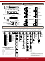
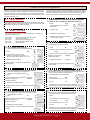
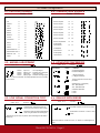
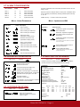
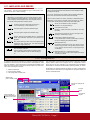
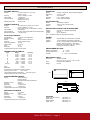
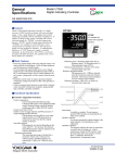
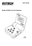
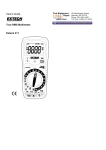
Series TAS
Panel Meters
FEMA ELECTRÓNICA
Panel meters 96x48 mm
Model TAS-TP
for process signals,
temperatures, resistances,
and potentiometers
Panel meter for process signals in mA and Vdc, both active and passive,
temperatures from Pt100 and thermocouples, resistances and potentiometers.
Instrument with 96x48mm housing and standard 14mm digit height, includes
excitation voltage for transducers. Power options in AC and DC, signal
retransmission and control options.
USER’S Manual
(1320r01)
User’s Manual TAS-TP
Model TP
Panel meter 96x48mm size for process, Pt100, thermocouples, resistances and potentiometer signals
Panel meter for process signals both active and passive, in
mA and Vdc, generated from 2 or 3 wire transducers. Includes
excitation voltage to power-up the transducer.
Size 96x48mm DIN standard instrument, with standard
14mm digit height, and 4 1/2 digit resolution (maximum
32000) and negative sign. Connections via plug-in screw
terminals and configuration via front push-buttons. For ap-
plication on industrial environments.
Power options in AC and DC and additional control and/or
retransmission modules. The instrument can manage up to
4 alarms.
Order Reference
Model
TAS
-
TP
Power
-
-
0
-0
-1
-6
Option1
230 Vac
115 Vac
24 Vdc
---EXP
-AL2
-AL4
Option2
-
---TSAT
-R485M
-TEK
Option3
-
---TEK
Read first
* When the instrument is powered, a message displays the
configured signal (see section 2 or section 4)
* If while in operation, the instrument shows a message on
display see section 4.11 «Messages and Errors»
* The frontal keypad of the instrument has two functions,
«numerical» and «direct access» function :
Key AL - Access to the alarm setpoint
Key HI - High display value (High)
Key LO - Low display value (Low)
Key ADJ - Field correction
Key DP -Decimal Point position
PROG - introduce programming codes
(4 digit codes, see section 4)
* MESSAGE «TIME».- The current programing procedure
has been stopped because there has been no interaction
from the user for the last 5 seconds
* SIGNAL RANGES.- To work with a signal range which is not
directly shown in this manual, select the closest upper range
and change the calibration parameters with code [14 11].
* Example .- to configure a 0/5 Vdc signal from a 0/10 BAR
transducer :
1.- select the 0/10 Vdc range
2.- enter code [14 11]
3.- edit 0 Vdc = 0 and 5 Vdc =10,000
* If afterwards the value of 10.000 needs to be changed, it
can be directly accessed and changed with key «HI».
FEMA ELECTRÓNICA - Page 2
User’s Manual TAS-TP
0 Front view
1 Signal connections
Display Value
5 displays 7 segment
Alarm Status
1,2,3 and 4
Connections for Temperature Connections for Process Signals
Signals
Led indicating
operation
E
D
C
B
A
0...25 mV
0...100 mV
0...1 V
0...10/50 mA
0...4/20 mA
E
D
C
B
A
0/10 V
0/100 V
E
D
C
B
A
-100/+100mV
-5/+5 mA
-1/+1 mA
E
+
D
THERMOCOUPLE
C
B
A
E
D
C
B
A
-10/+10 V
E
D
C
B
A
E
D
C
B
A
Units
E
D
C
B
A
PT 100
2 wires
E
D
C
B
A
PT 100
3 wires
+
-
Decimal point
Keypad Function led
(Red numerical, Green direct access)
6 key programming pad
double function
E
D
C
B
A
Connections for
optional boards
Input Signal
E
D
C
B
A
+
-
Power
2 1
PC Configuration
jack connector
Phase (-)
Vexc output
+
and Vexc adjust 10...24Vdc
(not in all models)
Earth
Phase (+)
+
-
PT 100
4 wires
+
-
Potentiometer
Resistance
2 Programming menu
t
ra
s
es
oc
Pr
pe
e
ur
rm
m
Te
11 XX
12 XX
1
rm
2
rm
3
rm
a
Al
a
Al
a
Al
a
Al
13 11
13 12
13 13
13 14
4
re
ste M
Hy d S
an
g
itin s
Ed ent
m
m
Te
13 15
14 11
14 12
12 11
Thermocouple K
AL 1 ACTIU
11 12
12 12
Thermocouple J
OFF
0/100mVdc
11 13 0/10Vdc
12 13
Thermocouple E
11 14 0/20mAdc
12 14
Thermocouple T
11 15 4/20mAdc
12 15
11 21 0/50mAdc
Thermocouple R
12 21
Thermocouple S
11 22 10/50mAdc
12 22
11 23 -10/+10Vdc
Thermocouple B
12 23
Thermocouple DIN J
11 24 -100/+100mVdc
12 31
PT 100/2 wire
11 25 -5/+5mAdc
12 32
PT 100/3 wire
11 31 -1/+1mAdc
12 33
PT 100/4 wire
ON
↵
1
AL LO
AL HI
ALSET HIST
EDIT IN LOXXXXX
1
2
CENTR
3
1
↵
↵
SMODE
ON
↵
INPUT
↵
1º
0.1º
↵
IN HI XXXXX
DL1 XXXXX
DI HI XXXXX
LED
1
Alarm Setpoints
Correcting the HIGH input signal
Correcting the HIGH input signal
Adjusting the LOW Indication
Adjusting the HIGH Indication
Decimal Point Position
INV
DIR
1
ON
OFF
PASSWORD XXXX
DEF CONFR
↵
↵
INPUT
ON
OFF
1
1
ONERR
ON
OFF
↵
FIL 1
FIL 2
1
2
3
INPUT
ADJT
1
1
TARE
HI LO
1
1
↵
INPUT
↵
1
1
ITS
ITS90
AVERA
REAL
1
1
↵
1
1
↵
1
↵
INPUT
FIL 3
↵
ITS68
↵
TEXT
INPUT
14 22
ADQN
385
↵
↵
1
1
ALFA
392
Configuration : Direct Access
ON
↵
1
1
↵
↵
↵
↵
11 51 0/100Vdc
OFF
FILT
ON
11 42 POT2 < 400 Ohms
DISPLAY NULL
14 21
↵
LAST
1
1
CJ
OFF
14 15 *
↵
↵
↵
HIST XXXXX
11 43 Resistance < 5 K
1
1
RESOL
1
14 14
↵
↵
1
OFF
AL-1 XXXXX
ºC
↵
DI LO XXXX
14 13
TEMP UNITS
ºF
iza
INPUT
1
↵
STRING XXX
↵
INPUT
FEMA ELECTRÓNICA - Page 3
rs
te
e
pe
l
m
na Ty
ra
Sig tion et t Pa
w c
s ul
Lo orre
Re efa
C
D
at
re
ad *
rT
o
yp ng
r
Er ent
Ke cki
m
Blo
n
tio
al
su
Vi
↵
RIGHT
LEFT
TIPE
11 32 0/25mVdc
11 41 POT1 < 5K
1
1
e
ur
t
ra
pe
↵
↵
11 11 0/1Vdc
t-
us
j
Ad
sis
STEP XXXXX
↵
INPUT
* IMPORTANT:
Before validating a PASSWORD with the
Keypad Blocking menu, remember the 5 digit
number you are about to enter. The instrument
will not accept any future order until the same
5 digit password is reintroduced.
User’s Manual TAS-TP
3 Direct access configuration
Section 3.1 shows how to enter a code to select a defined input signal range.
Codes are indicated in section 2. Examples in section 3.2 show how to use
Direct Access buttons on frontal keypad in order to configure a input of 4/20
mA with an indication of 0.0 / 250.0 using the field correction signal function
«ADJ HI» and «ADJ LO».
3.1- INPUT SIGNAL
The TAS units have several built-in predefined input signal ranges, selectable with the help of codes (4 digit codes). On page 4 there is a list of all
accessible ranges and the codes associated.
The frontal keypad has several direct access buttons for a quick configuration of the instrument :
- Correct the LOW or HIGH input levels
- Decimal Point Position
- Set for the LOW indication level
- Set for the HIGH indication level
- Alarms Setpoint
4- Message showing the selected range
«4 20» during 1 second
3.2.4- ALARM SetPoints
Fix the setpoint for Alarm1 at 10500
4- Validate the changes
↵
message «INPUT» shows the configuration has
been accepted
AL
pressing ↵
message «INPUT» shows the configuration has
been accepted
3.2.2- ADjustING THE LOW INDICATION VALUE
For the low input level (4 mA) we want to
configure a low indication of 000.00
3.2.5- CORRECTING THE LOW INPUT SIGNAL (OFFSET)
Allows offset correction, by linking the current input signal on terminals to the Low Indication Value memorized.
1- Generate the low input level signal
Lo
2- Press Adjust
Adj
The instrument asks «Hi» or «Lo» ?
2- Current value for the low indication is displayed.
Modify it by pressing on
1,2,3,4,5
until we see 00000
3- Validate the changes pressing
3- Validate the code pressing ↵
3- Current value for Alarm1 setpoint is displayed.
Modify it by pressing on 1,2,3,4,5
until we see 10500
2-message «DP» during 1 second
Press 2 to fix decimal point position 3
(To fix at other positions, press 1,2,3,4 or 5)
1- Press
11 15
2- Enter the number of the alarm we want to
modify 1
DP
3- Validate changes pressing 1- Press
Prog
message «Prog» during 1 second
blank screen
1- Press
3.2.1- decimal POINT POSITION
Activate the Decimal Point at position XXX.XX
1- Press
ConfigurING A 4/20mA INPUT SIGNAL RANGE
(Code 11 15 ; as shown on table on section 2)
2- Input the code 3.2- DIRECT ACCESS
Pad 1 (ADJ)
Pad 2 (DP) Pad 3 (LO) Pad 4 (HI) Pad 5 (AL) It is also possible to directly configure the relation input signal Vs reading
using the configuration code [14 11]. The following example is for a process
instrument. Temperature instruments do not allow to modify the display,
because the indication is direct from the temperature probe signal.
3- Press ↵
Lo
message «INPUT» shows the configuration has been
accepted
4- Message «Cr Lo» shows the unit has corrected the
low level value, linking the current input signal value
to the low indication value memorized (LO keypad)
3.2.3- ADjustING THE HIGH INDICATION VALUE
For the high input level (20 mA) we want to configure
a high indication of 100.00
1- Press
Hi
3.2.6- CORRECTING THE HIGH INPUT SIGNAL
Allows to link a current signal at the input terminals
to the High Indication Value memorized on the HI
keypad.
2- Current value for the high indication is displayed.
Modify it by pressing on 1,2,3,4,5
until we see 10000
1- Generate the high input level signal
3- Validate the changes pressing
↵
message «INPUT» shows the configuration has been
accepted
2- Press Adjust
Adj
The instrument asks «Hi» or «Lo» ?
3- Press Hi
4- Message «Cr Hi» shows the unit has corrected
the high level value, linking the current input signal
to the high indication value memorized (HI keypad)
FEMA ELECTRÓNICA - Page 4
User’s Manual TAS-TP
4 Codes configuration
4.1- ProcesS Signals
4.4- Temperature signals
Codes : 11 XX
Input
Code
0/1V
11 0/100mV
0/10V
Codes : 12 XX
Message
Input
CodeMessage
11
Thermocouple K
12
11
11
12
Thermocouple J
12
12
11
13
0/20mA
11
14
Thermocouple E
12
13
4/20mA
11
15
Thermocouple T
12
14
0/50mA
11
21
Thermocouple R
12
15
10/50mA
11
22
Thermocouple S
12
21
-10/10V
11
-100/100mV
11
Thermocouple B
12
22
-5/5mA
11
25
Thermocouple DIN J
12
23
-1/1mA
11
31
0/25mV
11
32
PT100 (RTD)
2 wire technic
12
31
potentiometer<5K 11
41
potentiometer<400 11
42
PT100(RTD)
3 wire technic
12
32
resistance <5K
11
43
0/100V
11
51
PT100 (RTD)
4 wire technic
12
33
23
24
4.5- ADVANCED TemperaturE
4.2- MANUAL ADJUSTMENT
Code : 14 11
Parameters
Function :
Values
number
number
number
number
Input Low -
Display Low -
Input High -
Display High-
Code : 14 12
Function
Parameters
Function :
Values
Function
Centigrade Degrees
Fahrenheit Degrees
Low Input Signal
Indication for Low Signal
High Input signal
Indication for High Signal
1 degree resolution
0.1 degree resolution
Code 14 11 can be used both to modify adjustments and to visualize
current values.
Thermocouple Col Junction Compensation
Standard for PT-100 (RTD)
385 - DIN Standard
392 - ANSI Standard
Calibration Standard
ITS 68
ITS 90.
4.3- LOW SIGNAL CORRECTION TYPE*
Code : 14 21
Parameters
4.6- DEALING WITH ERRORS
Code : 14 14
Function :
ValuesFunction
Parameters
Function :
ValuesFunction
TARE function. Adjusts the low level
moving the high level the same quantity.
Activates all alarms in case of error state *
Adjusts low and high level independently,
when using ADJ Direct Access keypad.
Deactivates all alarms in case of error
state*
* Selects the type of action to perform when selecting the ADJ Direct
Access key.
* More information on «what is an error», on section 4.7 «Messages and
errors»
FEMA ELECTRÓNICA - Page 5
User’s Manual TAS-TP
4.7-ALARM CONFIGURATION
Alarm Number
CODEMenu
Alarm 1
Alarm 2
Alarm 3
Alarm 4
General
13
13
13
13
13
11 12
13
14
15
The alarm configuration menu list several parameters to which we must
assign a value.
Alarm Parameters
Alarm Parameters
Alarm Parameters
Alarm Parameters
Hysteresis and SM
Numerical values are assigned with the number pads. Predefined values
(such as ON/OFF) are selected by selecting available options with keys
‘1’, ‘2’ or ‘3’.
Validate with key ’↵’ in order to access next parameter.
Menu : Alarm Parameters
Parameters
Menu : Hysteres and SM
Parameters configured on this menu apply to the 4 alarms
Values Description
Parameters
Alarm1 working
Alarm1 not working
ValuesFunction
Hysteresis is applied to the process of
alarm deactivation*
Alarm1 working as «maximum»
Alarm1 working as «minimum»
Band alarm. Hysteresis is applied to
the process of alarm activation and
deactivation*
Setpoint for Alarm1
(expressed in display points)
Hysteresis is applied to the process of
alarm activation.*
Hysteresis value (max. 255)
(expressed in display points)
*The hysteresis points are defined on parameter
HYST for each alarm.
Delay on relay activation
(expressed in seconds)
Security Mode activated on alarms
acting as «minimum»**
Led is active when alarm is active
Led is active when alarm is inactive
Security Mode deactivated
Alarm text active
Alarm text inactive
**Output relay are inactive until the set point is
reached for the first time.
Text associated with alarm led
4.8-ADVANCED VISUALIZATION
Code : 14 13
Parameters
Code : 14 22
Function :
ValuesFunction
No zeros active to the left
Zeros active to the left
Fixes the least significant digit to zero
Frees the least significant digit
Fast filter on the input signal : 0.25 Sec 98%
Medium filter on the input signal : 0.5 Sec 98%
Slow filter on the input signal: 1 Sec. 98%
Real time indication
Indication of mean values
Time (between 1 and 255 seconds) to calculate
mean values for mean indication
Code : 14 15
Values
Function :
Function
Blocks the frontal keypad
Password is made of a numerical
value of 5 digits
Function :
Resets the unit to the default manufacturing values. It is needed to
reconfirm the action by pressing INTRO after the message
Parameters
Default Values
Input Signal
Lo - Low Level Indication
HI - High Level Indication
Decimal Point
Acquisition Mode
STEP
Zero Blanking Last digit to zero
Display Filter
Temperature Units
Temperature Resolution
Temperature : ALFA Parameter
Temperature: Measuring Standard
Password
4.9- BLOCKING THE KEYPAD
Parameters
4.10-ResetTING THE INSTRUMENT
Alarm 1
Alarm 2
Alarm 3
Alarm 4
Setpoint
Hyst
ON
ON ON
ON
1000
1000
1000
1000
4/20mA
0
10000
0 0 0 0 0.
Real
10
ON
OFF
Filter 2 (0.5 sec.)
ºC
0.1º
ALFA 385
ITS 68
deactivated
Delay Type Led Text String
1
1
1
1
0
0
0
0
HI
HI
HI
HI
Hysteresis Security Mode
On Error
OFF
FEMA ELECTRÓNICA - Page 6
DIR
DIR
DIR
DIR
OFF
OFF
OFF
OFF
CENTER
ON
AL-1
AL-2
AL-3
AL-4
User’s Manual TAS-TP
4.11-MeSsaGes AND Errors
Messages and errors are active when the instrument senses a «not normal» situation . The instrument identifies the type of «abnormality» and
informs with an error or with a message.
Messages
«Messages» are associated with non-critical situations, those
which only affect the measure temporary. The «message» remains
active on display until the situation clears. The instrument recovers
the normal working state when situation clears..
Errors
«Errors» are associated with critical situations which disable the ability
to measure the signal.
The «error» remains active on display until the situation disappears.
At this time, the instrument recovers normal functionality.
«Errors» execute actions on alarms, activating or deactivating them
depending on the status of variable OnErr (see page 11). Alarms
recover their normal behavior when the the error state clears.
Current on the loop is lower than the minimum.*
*On a 4/20mA loop, current is below 4 mA
Sensor not connected or open connection
(example : PT100 probe broken)
The input signal is lower than selected range
Connections not correct
(example : cables incorrectly connected on the input
terminals)
The input signal is higher than selected range
The current loop is open or current in the loop is zero
(example : 4/20mA loop is open)
Security waiting time exceeded while in configuration
mode. The instrument rolls-back to the previous configuration
Internal Error. Restart the instrument.
** It is possible that no action is performed on alarms if
this error is affecting the internal EPROM
Error when entering a data. Value not accepted. Reintroduce the value. (Typical case : The value assigned to
hysteresis is higher than 255)
Mathematical Error 0
Parameters introduced for the input signal are not
coherent. (Typical case : the high level value is similar
or very close to low level value, on input signal range
or indication)
Error on Display Indication
Trying to display a value higher than 32000 or lower
than -19999. Reduce HI and LO levels dividing by
10.
Mathematical Error 1: mathematical overflow.
The unit is trying to process values higher than 32000
or lower than -32000.
5 PC configuration
To configure TAS unit from software you need the configuration software
(available on www.fema.es) and the PCConnector cable (Optional, check
with your distributor). The PCConnector is connected to the SUB-D 9 pins
serial port of the computer and the communications jack to the TAS instrument. When executing the software:
1.- Select the COM port
2.- Press «START COMM»
2.- The configuration windows open
The configuration of the instrument and the alarms is done from the main
display window. Options are configured from an independent window
which opens to the right. Changes in the configuration are automatically
downloaded, or can be forced to download by pressing «WRITE_D» button.
Configuration can saved to a file with the «SAVE_F» button. Configurations
for the instrument and alarms and configuration for the option boards are
saved in independent files.
Select COM
press «START COM»
Window to configure the
options
Process
Adjust
Input signal
ranges
Press «WRITE_D»
to force download configuration to the instrument
FEMA ELECTRÓNICA - Page 7
User’s Manual TAS-TP
Technical data
VOLTAGE SIGNALS
Ranges
Accuracy
Thermal Drift
Input Impedance
Effective Resolution
0...25mV, 100mV, 1V, 10V, 100V
±100mV, ±10V
0,05% of reading ± 1 point
± 100 ppm/ºC
10 MOhm for Vin<1V
500KOhm for Vin>1V
32.000 points
CURRENT SIGNALS
Ranges
Accuracy
Thermal Drift
Input Impedance
Effective Resolution
0/4...20mA, 0/10...50mA, ±1mA, ±5mA
0,05% of reading ± 1 point
(plus 0.02% F.S. for 4...20mA and 10...50mA)
± 100 ppm/ºC
3V drop, 10 Ohms (equivalent to 160 Ohm at 20mA)
> 32.000 points
PT100 (RTD) SIGNALS
IndicaTION
Display Digit Height Filter Indication
Refresh
5 Digits, 7 Segments , Red Led High Brightness
14,2 mm. / 0,56’’
Anti-reflexive.
From - 19999 to 32000
5 /sec. (Filter selectable)
A/D CONVERTER
Speed
Accuracy
CMRR
14 Readings / Second
16 BIT + sign (± 65.000 points)
> 130 dB
excitation VOLTAGE FOR TransducERS
Voltage
10 to 24 Vdc. regulated (adjustable)
Isolation
500 Vdc
Current
50 mA. Maximum
Note .- Excitation Voltage not included in all models
Configuration
2, 3 and 4 wire configurable
Excitation current
250 uA
Range
-200 to +850ºC (4-400 Ohm)
Accuracy
±0,3ºC Typical (±0,5ºF)
Cable Compensation
10 Ohm
Thermal drift
0.1ºC / ºC
Units
ºC / ºF
Resolution
1º / 0,1º
Programmable response to sensor break
Standard
Optional
Optional
THERMOCOUPLE SIGNALS
Working Temperature Storage Temperature
Humidity
TypeRange
J-210ºC ... +750ºC
K-270ºC ... +1370ºC
T-270ºC ... +400ºC
B 0ºC ... +1800ºC
E-270ºC ... +1000ºC
R -50ºC ... +1770ºC
S -50ºC ... +1770ºC
DIN «J»-210ºC ... +750ºC
POWER
230 Vac 50/60 Hz. Consumption 3,5W Max
115 Vac 50/60Hz. Consumption 3.8W Max
24 Vdc (±10%) isolated. Consumption 4W Max
Isolation 1000 Vdc (Primary - Secondary)
Maximum consumption at 24 Vdc .- 265 mA
Peak current at start-up <600mA
ENVIRONMENTAL DATA
Accuracy
0,5 ºC
0,5 ºC
0,5 ºC
1,0 ºC
0,5 ºC
0,7 ºC
0,7 ºC
0,5 ºC
0 ... + 50 ºC
-20 ... + 85 ºC
0 ... 85%, non condensated
MECHANICAL DATA
Dimensions
Front Weight
Units
ºC / ºF
Resolution
1º / 0,1º
Cold Junction Compensation Internal / External
Accuracy for the «CJC»
0,5ºC a 25ºC
Thermal drift included compensation
0,15ºC/ºC Typical
Programmable response to sensor break
Standard 1/8 DIN
96 x 48 x 124 mm. (3,78” x 1.89” x 4,88”)
Protection IP65 (NEMA 4)
0,5 Kgs
92mm
48mm
44mm
POTENTIOMETER SIGNALS
Range
100 to 400 Ohms
400 to 5 KOhms
Expansible with external resistance
Excitation current
250 uA
Accuracy
0,05% F.S.
Resolution
>10.000 Points
Thermal drift
± 100 ppm/ºC
Programmable response to sensor break
96mm
124mm
ResistAnce SIGNALS
Range
0...5 KOhm
Excitation current
250uA
Accuracy
1 Ohm ±1 point
Resolution
0,2 Ohm
Thermal drift
± 100 ppm/ºC
Programmable response to sensor break
2mm
OPTIONS
Option EXP, AL2 and AL4 see section 7.1
Option TSAT see section 7.2
Option R485M see section 7.3
Option TEK see section 7.4
FEMA ELECTRÓNICA - Page 8
15mm
User’s Manual TAS-TP
7 Options - installation and configuration
The TAS instruments allow several different options to be added to the
standard unit. Several requirements between options are needed in order
to add an option to a standard TAS unit. Not all options can be added to
the same instrument at the same time.
EXP
AL2
AL4
Optional
Board
Tarjeta de Salida
Analógica(Analogue, Modbus or TEK)
Expansion Bus
2 Relay Outputs and Expansion Bus
4 Relay Output (without Expansion Bus)
Expansion
Board
Módulo de Expansión
Note .- Only 1 of these options can be added to the instrument
TSAT Analogue output. Requires Expansion Bus option.
Not compatible with R485M option
R485M Modbus Output. Requires Expansion Bus option.
Not compatible with TSAT option
Note .- Only 1 of TSAT or R485M can be added to a TAS instrument, the
unit must have also the Expansion Bus
TEK
Remote Contacts. Requires Expansion Bus option.
Note .- Can only be added if the TAS instrument has the Expansion bus
option. The TEK option can share the bus with 1 TSAT or with 1x R485M
or can be installed alone.
7.1- OPTIONS EXP, AL2 AND AL4
Option AL2 The EXP allows other options (TSAT, R485M and TEK)
to be added to a TAS instrument, without adding relays.
Option board with 2 Relay output contacts
Relays are controlled by alarms 1 and 2
Includes «Expansion Bus» which allows more options
to be installed (TSAT, R485M, TEK)
AL2
Common
Normally Closed
Normally Open
Option board with 4 Relay output contacts
Relays are controlled by alarms AL1, AL2, AL3 and AL4
No additional options can be added
AL4
Technical data on relays
AL1
NC
NO
COM
COM
NO
NC
NC
NO
COM
COM
NO
NC
COM
NC
NO Option AL4.-
Connections for options
TSAT, R485M and TEK
COM
NC
NO
NO
NC
COM
Option EXP
Connections for options
TSAT, R485M and TEK
COM
NC
NO Common
Normally Closed
Normally Open
Type ON/OFF
Maximum Current 2 A. (non inductive)
Maximum Voltage 250 Vac
Terminals isolated between each other
isolated from power supply
isolated from signal
FEMA ELECTRÓNICA - Page 9
AL3
AL2
AL1
User’s Manual TAS-TP
7.2 - ANALOG OUTPUT - TSAT OPTION BOARD
The TSAT board adds analog output capabilities to the TAS instruments.
Jumper selectable for voltage ( 0/10 Vdc) and for current (4/20mA and
0/20mA in modes SINK and SOURCE) adds a galvanic isolation of 2KVeff.
The analog output adjustment is done via the frontal keypad. The analog
output value is adjusted related to the display indication. This allows the
intelligent use of the correction functions for offsets and fast readjustment
Voltage Output
Terminal 12 (Negative)
Terminal 13 (Positive)
Terminal 13
+ (Polo 13)
Rl
Terminal 12
- (Polo 12)
Current Output Source type (Active)
Terminal 13 (Negative)
Terminal 14 (Positive)
Rl
of the TAS series, meaning that when readjusting the input/display readings,
the analog output does not need to be readjusted most of the times.
in case of trouble with the input signal, such as loop break or sensor break,
the analog output signal will exhibit always the same behavior predefined by
the operator on the menu.
Terminal 14
Terminal 13
Terminal 12
Terminal 14
+ (Polo 14)
Terminal 13
- (Polo 13)
Current Output Sink type (Passive)
Terminal 12 (Negative)
Terminal 13 (Positive)
Note .- Sink Current set-up needs
external power supply
Rl
Vext
Terminal 13
(Polo 13)
+
-
Terminal 12
(Polo 12)
Technical Data
Output Signals
Resolution
Accuracy
Ripple
Thermal Drift
Pass Band
Response Time
Isolation Levels
0/10 Vdc, 0/20 mA and 4/20 mA (and others)
12 bits
<0.1% FS
<0.01% FS
100 ppm/ºC
1.5 Hz (-3 dB)
250 ms (99% of indication)
2KVeff (50 Hz, 1 minute)
mA Output
RLmax 500 Ohms (Source Mode)
Imax
21.5 mA approx.
SINK Output maximum 40Vdc on terminals
Vdc Output
RL min
Vmax
Jumpers to the left.Output in Vdc
Jumpers to the right.Output in mA
1 KOhm
11 Vdc approx.
Start-Up procedure
1.- Place jumpers on TSAT board for Vdc or mA output
2.- Plug the TSAT board on the bus pins (Expansion Bus) on board AL2
or EXP
3.- To configure the analog output you need to know the analog output signal
and the related display indication
Input Signal
4 mA
20 mA
Indication
0
100.00
Analog Output
0 Vdc (00000 millivolts)
10 Vdc (10000 millivolts)
Note .- Analog output units are entered with 3 decimals, this is, in millivolts
and microAmperes.
4.- Make connections, power the unit and configure the board (see next page)
FEMA ELECTRÓNICA - Page 10
User’s Manual TAS-TP
Entering the Menu
55 11
Introduce the programming code «55 11»
Message «IC ANG» Analog Output board recognized
Message «MENU» Entering the programming menu
Message «4_20» or «0 10» Shows the operating mode selected
by jumpers (Vdc or mA)
------
↵
IC ANG Menu
4_20 ó 0_10
Adjusting the Analog Output
d_LO
*Note .- The values for the following 4 parameter are setable using keys
1,2,3,4,5
Parameter «d_LO» Display value for the low analog output signal
(Display Low)
↵
o_LO
Parameter «o_LO» Analog output value for the «d_LO» value *
(Output Low)
Parameter «d_HI» Display value for the high level analog output
(Display High)
↵
d_HI
Parameter «o_HI» Analog output value for the «d_HI» value*
(Output High)
Note .- values for «d_LO» and «d_HI» are in microVolts or microAmperes
↵
o_HI
Behavior when Error
Parameter «OnErr» .- Behavior when an «error» occurs
«DIR» Analog Output up to Full Scale (11Vdc or 21mA approx)
«INV» Analog Output down to zero ( -0.5 Vdc or 0mA approx)
↵
onErr
Note .- see section 4.11 for a description on «error» conditions
Exiting the Menu
DIR
INV
↵
Message «INPUT» Confirms that the parameters have been accepted
Message «ERROR» Informs that at least one of the values is not
correct, and the whole configuration could not be applied. Repeat the process
from the beginning.
FEMA ELECTRÓNICA - Page 11
INPUT or ERROR
IC_OFF
1
2
User’s Manual TAS-TP
7.3- MODBUS OUTPUT - R485M OPTION BOARD
The R485M board adds Modbus communication capabilities to the TASunits, for retransmission of visualized data to a remote element. The board
is isolated and is completely configurable from frontal keypad.
Protocols
Bus Speed
Addresses
Distances
Isolation ModBus RTU and ModBus ASCII selectable
RS485 Half Duplex
(EIA-RS485)
shielded twisted pair cable, in line,
closed with terminator
2400, 4800, 9600, 19200, 38400 bauds
from 0 to 99
1200 meters per BUS segment
4800 meters with repeaters
2 KV with input signal
3.5 KV with power signal
Accepted Functions
[04] HRegister Read
(«Input Register» in the standard)
Register Map
[00 00] H value on display
Type Integer
Value from -32768 to 32768
[00 01] H Decimal Point position
Type Integer
Value 0, 1, 2, 3, 4
0= No decimal point
1 = 1 Decimal
2. = 2 Decimals
3 = 3 Decimals
4 = 4 Decimals
5 = 5 Decimals
[00 02] H Instrument Status
Type Integer
Configure MODBUS output
Introduce the programming code «55 11»
Message «IC 485»
RS485 board recognized
Message «MENU»
Entering the programming menu
Parameter «PROT»
Protocol
Select Modbus ASCII or Modbus RTU
Parameter «DIR»
Address
Input instrument address
Parameter «BAUDS» Speed in Bauds
Parameter «n BIT»
Number of Bits
Select 8 or 7 bits per character
Parameter «t PAR» Parity
«Even» «Odd»
Message «INPUT» .- confirms that the parameters have been accepted
Message «ERROR» .- informs that at least one of the values is not correct,
and the whole configuration could not be applied. Repeat the process from
the beginning.
55 11
Word composed fo 5 bits (1+4 bits)
b0=0 register [00 00]H is valid
b0=1 register [00 00]H is not valid
b3
↵
- - - - - - IC 485
Menu
Prot
M Asc
M rtu
b4,b3,b2,b1
0 = Reserved
1 = Low
2 = -Ovr
3 = +Ovr
4 = DErr0
5 = Brk
6 = Con
7 = Open
8 = MErr0
9 = MErr1
10 to 15 = Reserved
Not Used b4
«nPar»
↵
Dir
↵
Bauds
2400
4800
9600
19200
38400
b2
b1
b0
↵
n bit
8 bit
7 bit
b3
b2
b1
1
2
3
4
5
1
2
↵
[00 03] H Alarms
Type Integer
b0 = 0 / 1 AL1 is OFF / ON
b1 = 0 / 1 AL2 is OFF / ON
b2 = 0 / 1 AL3 is OFF / ON
b3 = 0 / 1 AL4 is OFF / ON
Not Used 1
2
t Par
n Par
Even
Odd
↵
b0
Note 1 : If there is no numeric value on display (but a text value), register
0000Hex offers value 32767 or -32768. And bit b0 of register 0002Hex
show the display status.
Note 2 : The length of all registers is 2 bytes, defined as LSB and MSB.
MSB (Most Significant Byte) is the first to be transmitted. LSB (Least
Significant Byte) us the second to be transmitted
FEMA ELECTRÓNICA - Page 12
Input IC OFF
1
2
3
User’s Manual TAS-TP
Connections .Cables A and B as
Standard Modbus
Terminator .- Place jumper if the BUS
ends on this instrument
Terminal 14 - B
Terminal 13 - A
7.3.1 MODBUS STRUCTURE
Example for a Modbus-RTU frame .- Start Character corresponds with instrument address and final character
corresponds with the CRC Security Code
In Modbus-ASCII Start and End characters are specific
T1 = Time between two characters
T2 = Time between end of question and start of response
T3 = Time between end of response and start of next question
T2 MAX
(RTU and ASCII)
38400
19200
9600
4800
2400
4.3 msec
5.7 msec
9.2 msec
15.5 msec
27 msec
T1 (min/max)
RTU ASCII
0CT / 3CT
0CT / ---
Character Structure
Bit structure for the characters on protocols ModBus RTU and ModBus
ASCII
START
DATA
PARITY STOP
TOTAL BITS
RTU
1
1
1
8
8
8
P
I
--
1
1
2
11
11
11
ASCII
1
1
1
7
7
7
P
I
--
1
1
2
10
10
10
Frame Structure
QUESTION : Communication MASTER and SLAVE
ADDRESS
FUNCTION
READING START REGISTER NUMBER OF REGISTERS TO READ
CRC
1 CHARACTER
1 CHARACTER
2 CHARACTERS
X CHARACTERS
2 CHARACTERS
Instrument Address
Function 04H, register read
Register 00 00H = Display Value
02 = 2 registers (4 bytes)
Control Checksum
1 CHARACTER
1 CHARACTER
1 CHARACTER
X CHARACTERS
2 CHARACTERS
Instrument Address
Function 04H, register read
Number of data characters following
Response data*
Control Checksum
RESPONSE : Communication SLAVE to MASTER
ADDRESS
FUNCTION
LENGTH
DATA
CRC
FEMA ELECTRÓNICA - Page 13
T3 (min/max)
RTU ASCII
3.5CT / ---- / ---
User’s Manual TAS-TP
7.4- PEAK, VALLEY, HOLD, TARE, RESET- OPTION TEK
The TEK option adds functions for PEAK/VALLEY memory, or remote TARE
or remote HOLD to the instruments TAS. These functions are selectable
and programmable from frontal keypad, and are activated connecting two
external contacts to the rear side terminals. Each contact has assigned one
Functions
PEAK
VALLEY
HOLD
TARE
RESET
Contact1
YES
YES
YES
YES
YES
Contact2
YES
YES
YES
NO
NO
function (which can be changed) plus a third function associated to both
contacts closing at the same time, to release a RESET for PEAK/VALLEY
memory. Isolated option.
Terminal 12.- COMMON
Terminal 15.- CONTACT1
Terminal 16.- CONTACT2
Note .- the function assigned to Contact1 and Contact2 are configurable
from frontal keypad.
Terminal 16
Terminal 15
Terminal 12
Note .- «TEK» board can be configured to release a «RESET» of the
«PEAK» and the VALLEY values when both Contact1 and Contact2 are
simultaneously closed.
Isolation Levels
2KV to the input signal
3K5V to the power 230Vac and 115Vac
1KV to the power 24Vdc
14 23
↵
E INP
Entering the Menu
INP_1
Introduce the programming code «14 23»
Message «E INP» TEK board recognized
ON
OFF
Configuring the external contacts
↵
Parameter «INP_1»Contact 1
ON
Active
OFF Not Active
Parameter «FUN_T»
FUN_T
HOLD
Function assigned to Contact1
MMIN
MMAX
Parameter «INP_2» Contact 2
ON
Active
OFF
Nor Active
RESET
Parameter «FUN_T»
↵
TARE
Function assigned to Contact2
Parameter «RES12» RESET12
Function «Reset» when connecting
contacts 1 and 2 simultaneously
ON
Active
OFF
Nor Active
ON
OFF
3
4
5
1
2
↵
FUN_T
Message «INPUT» .- confirms that the parameters have been accepted
Message «ERROR» .- informs that at least one of the values is not correct,
and the whole configuration could not be applied. Repeat the process from
the beginning.
Default Configuration
HOLD
MMIN
MMAX
1
2
3
↵
RES12
When entering code «14 22» to apply a unit reset, the TEK
option is configured as follows :
1
2
INP_2
Exiting the Menu
1
2
STATEFUNCTION
CONTROL 1
OFF
CONTROL 2
OFF
CONTROL12
OFF
ON
OFF
1
2
↵
HOLD
HOLD
FEMA ELECTRÓNICA - Page 14
INPUT o ERROR
User’s Manual TAS-TP
8 CE declaration of conformity
Manufacturer FEMA ELECTRÓNICA, S.A.
Altimira 14 - Pol. Ind. Santiga
E08210 - Barberà del Vallès
BARCELONA - SPAIN
www.fema.es - [email protected]
Series TAS, models TP. VAC. VDC. IAC. IDC
The manufacturer declares that the instruments indicated
comply with the directives and rules indicated below.
9 Warranty
All instruments are warranted against all manufacturing
defects for a period of 24 MONTHS from the shipment date.
This warranty does not apply in case of misuse, accident or
manipulation by non-authorized personnel. In case of malfunction get in contact with your local provider to arrange for
repair. Within the warranty period and after examination by
the manufacturer, the unit will be repaired or substituted when
found to be defective. The scope of this warranty is limited to
the repair cost of the instrument, not being the manufacturer
eligible for responsibility on additional damages or costs.
Directive of electromagnetic compatibility 2004/108/CEE
Directive of low voltage 73/23/CEE
Security rules 61010-1
Emission rules 50081-2
Immunity rules 50082-2
Barberà del Vallès October 2009
Daniel Juncà - Quality Manager
10 Precautions on installation
PRECAUTIONS.- Installation and use of this unit must be
done by qualified operators. The unit has not AC (mains)
switch, neither internal protection fuse, and it will be in
operation as soon as power is connected. The installation must contain an external mains switch with protection fuse plus the
necessary devices to protect the operator and the process when using the
unit to control a machine or process where injury to personnel or damage to
equipment or process may occur as a result of failure of the unit.
External Protection Fuse to be added :
for 230 Vac : 80mA fuse TimeLag as IEC 127/2
for 115 Vac : 125mA fuse TimeLag as IEC 127/2
SIGNAL WIRING.- Certain considerations must be given when installing
the signal input wires. Long wires can act like an antenna and introduce
electrical noise to the unit, therefore :
SAFETY PRESCRIPTIONS.- These instruments have been designed and tested according to 61010-1 rules and are delivered
in good operational conditions. This user manual contains useful
information for electrical connections. Do not make wiring signal
changes or connections when power is applied to the unit. Make signal connections before power is applied and, if reconnection is required, disconnect
the AC (mains) power before such wiring is attempted. Install the unit in a
place with good ventilation to avoid excessive heating, and far from electrical
noise sources or magnetic field generators such as power relays, electrical
motors, speed controls etc...
SAFETY CONSIDERATIONS
The unit cannot be installed in open places. Do not use until the installation
is finished.
If the unit shows signs of damage, or is not able to show the expected
measures, or has been stored in a bad conditions or a protection failure
can occur, then do not attempt to operate and keep the unit out of service.
IN CASE OF FIRE
POWER SUPPLY.- The power supply must be connected to the adequate
terminals (see connection instructions). Characteristics of the power supply
are showed on the characteristics label attached to the instrument. Please
make sure the unit is correctly connected to a power supply of the correct
voltage and frequency. Do not use other power supply otherwise permanent
damage may be caused to the unit. Do not connect the unit to power sources
heavily loaded or to circuits which power loads in cycle ON-OFF or to circuits
which power inductive loads.
WARNING.- On units with DC power supply, be careful with the polarity
indicated for each terminal.
Do not install the signal input wires in the same conduct with power lines,
heaters, solenoids, SCR controls etc...and always far from these elements.
When shielded wires are used, leave unconnected the shield on the indicator side and connect the other end of the shield to the ground terminal of
the machine.
PRESCRIPTIONS.- Before starting any operation of adjustment, replacement, maintenance or repair, the unit must be disconnected from any
kind of power supply.
Keep the unit clean , to assure good functioning and performance. To prevent electrical or fire hazard, do not expose the unit to excessive moisture.
Do not operate the unit in the presence of flammable gases or fumes, such
as environment constitutes a definite safety hazard. The unit is designed to
be mounted on a panel.
in any case.
IN CASE OF FIRE
1.- Disconnect the unit from the power supply.
2.- Give the alarm according to the local rules.
3.- Switch off all the air conditioning devices.
4.- Attack the fire with carbonic snow, do not use water
WARNING : In closed areas do not use systems with vaporized liquids.
FEMA ELECTRÓNICA - Page 15
other products
Panel Meters
Standard 96x48mm
Panel Meters
Small 72x36 mm
Panel Meters
Miniature 48x24 mm
Large Displays
60 & 100 mm digit
Signal Converters
& Isolators
Panel Meters
Standard 96x48mm
www.fema.es
ELECTRONIC INSTRUMENTATION FOR INDUSTRY
FEMA ELECTRÓNICA, S.A.
Altimira 14 - Pol. Ind. Santiga
E08210 Barberà del Vallès
BARCELONA - SPAIN
Tel. (+34) 93.729.6004- www.fema.es
Fax (+34) 93.729.6003- [email protected]