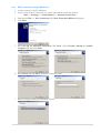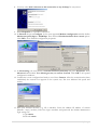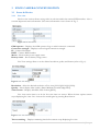
1
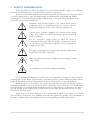
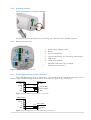
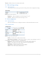
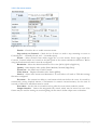
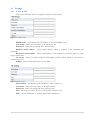
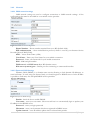
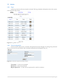
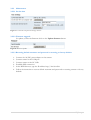
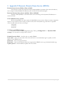
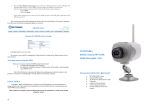
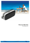
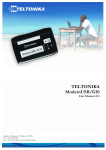
TELTONIKA
EDGE camera (MVC100)
User’s Manual 1.00
LEGAL NOICE
Copyright © 2008 TELTONIKA Ltd. All rights reserved. Reproduction, transfer, distribution
or storage of part or all of the contents in this document in any form without the prior written
permission of TELTONIKA Ltd is prohibited.
Other product and company names mentioned herein may be trademarks or trade names of their
respective owners.
ATTENTION
Before using the device we strongly recommend read this user
manual.
Do not rip the device. Do not touch the device if the device block
is broken or its connecting wires are without isolation.
All wireless devices for data transferring may be susceptible to
interference, which could affect performance.
The device is not water-resistant. Keep it dry.
The device requires high 230V AC voltage.
IMPORTANT NOTES!
It is mandatory to read the notes and manual carefully before starting to use the device.
2|Page
Table of Contents
1
SAFETY INFORMATION ....................................................................................................................................... 4
2
GETTING STARTED.............................................................................................................................................. 5
2.1 INTRODUCTION ......................................................................................................................................................... 5
2.2 PACKAGE CONTENTS ................................................................................................................................................... 5
2.3 INSTALLING THE HARDWARE ......................................................................................................................................... 5
2.3.1
Inserting SIM card ....................................................................................................................................... 5
2.3.2
Attaching antenna....................................................................................................................................... 6
2.3.3
Back panel overview .................................................................................................................................... 6
2.3.4
Typical PIR and door sensor connection ...................................................................................................... 6
2.3.5
Wall mounting ............................................................................................................................................. 7
2.4 INSTALLING THE SOFTWARE.......................................................................................................................................... 7
2.4.1
Installing USB drivers (Windows) ................................................................................................................ 7
2.4.2
PPP connection settings (Windows) ............................................................................................................ 8
2.5 ACCESSING THE CAMERA ........................................................................................................................................... 10
2.5.1
Accessing WEB interface ........................................................................................................................... 10
2.5.2
WEB configuration page interface structure ............................................................................................. 10
3
EDGE CAMERA CONFIGURATION ..................................................................................................................... 11
3.1 STATUS & REVIEW ................................................................................................................................................... 11
3.1.1
Live view .................................................................................................................................................... 11
3.2 VIDEO AND IMAGE SETTINGS ...................................................................................................................................... 12
3.2.1
Video parameters ...................................................................................................................................... 12
3.3 EVENT CONFIGURATION ............................................................................................................................................ 12
3.3.1
Stream & Events ........................................................................................................................................ 12
3.4 SETTINGS ............................................................................................................................................................... 14
3.4.1
E-mail & FTP .............................................................................................................................................. 14
3.4.2
Network ..................................................................................................................................................... 15
3.5 ADMIN .................................................................................................................................................................. 16
3.5.1
Logs ........................................................................................................................................................... 16
3.5.2
Users management ................................................................................................................................... 16
3.5.3
Maintenance ............................................................................................................................................. 17
4
TECHNICAL SPECIFICATION............................................................................................................................... 18
5
APPENDIX D DYNAMIC DOMAIN NAME SERVICE (DDNS) ................................................................................. 20
3|Page
1 SAFETY INFORMATION
In this document you will be introduced how to use camera safely. We suggest you to adhere to
following recommendations to avoid any damage to person or property.
You have to be familiar with the safety requirements before starting to use the device! Camera
is used for transmission of video and single images via GSM network using GPRS and EDGE
technologies. To avoid burning and voltage caused traumas, of the personnel working with device,
please follow these safety requirements.
Installation and technical support of the camera device can be
performed only by a qualified personnel or a person who has
enough knowledge about this device and safety requirements.
Camera device requires 12V 250 mA constant power supply
source that satisfies all safety requirements listed in LST EN
60950-1 standard.
The PC and power supply source, to which the device is
connected, should satisfy LST EN 60950-1 standard. The device
can be used on first (Personal Computer) or second (Notebook)
computer safety class.
The light or attachable sensors must satisfy all safety requirements
listed in LST EN 60950-1 standard.
Disconnect device from power supply before mounting to avoid
voltage effect!
Do not mount or serve device during a thunderbolt.
To avoid mechanical damages of the device it is recommended to transport the device packed
in damage-proof pack. While using the device, it should be placed so, that its indication LED would be
visible as they inform in which working mode the device is and if it has any working problems.
Protection against over currents, short circuits and earth faults should be provided as a part of
the building installation. Two pole protective device is required to protect from short-circuit and earth
false. The power of connected device should satisfy power of release device. To disconnect the device
plug off AC/DC power adapter from the wall outlet or power strip. The interstice between contacts
should be no less than 3mm.
Signal level of the device depends on the environment in which it is working. If the device
starts working insufficiently only qualified personnel may repair this product. We recommend to
forward it to repair centre or to manufacturers. No exchangeable parts inside of the device.
4|Page
2 GETTING STARTED
2.1 Introduction
Teltonika MVC100 EDGE Camera - compact mobile surveillance and monitoring system for
transmission of high resolution video and single images via GPRS/EDGE network, so even in places
with no Internet connection available - ideal for remote surveillance and monitoring of temporary or
distant sites or mobile assets. The images can be acquired automatically with programmable period
and/or upon external triggers such as motion sensors or door contacts. The video and single images
can be viewed on a PC or a handheld device, and can also be transmitted to FTP-server and/or by email.
2.2 Package contents
MVC100 EDGE Camera
External GSM antenna
AC/DC Power adapter (Euro or UK)
USB cable
Angled wall mount bracket
Leaflet “Quick Start Guide”
Note: The manufacturer does not supply the SIM card, which is mandatory for setting up a
connection to the GSM network! The SIM card may be purchased from your GSM (mobile) service
provider!
Note: If any of the components is missing or damaged, please contact the retailer or reseller
from which this product was purchased.
2.3 Installing the hardware
Before installing the hardware, check to make sure that all items listed in the package contents are in.
2.3.1
Inserting SIM card
Open and remove the back panel of the camera. To do that, use the screw-driver to loosen four
screws holding panel.. After the back panel is removed gently insert the SIM card as showed in figures
below.
5|Page
2.3.2
Attaching antenna
Screw the antenna in a clockwise direction.
Position the antenna upwards at its connecting joint. This will ensure optimal reception.
2.3.3
Back panel overview
1.
2.
3.
4.
5.
6.
7.
8.
Power supply adapter socket.
Battery
5-pin terminal block
5-pin terminal block for connecting external light
USB socket
LEDs (Not installed)
MicroSD card socket (Not installed)
GSM antenna connector
Figure 1. EDGE camera back panel view.
2.3.4
Typical PIR and door sensor connection
Door and PIR sensors may be attached to 5-pin terminal block located in back panel of the
camera. Typical PIR and magnetic door sensor connection are given in Fig. 2 and Fig 3.
EDGE Camera
PIR unit
VCC
IR LED
C1
+12V
4.7k
C2
Relay contact 1
Relay contact 2
GND
GND
Figure 2. Typical PIR sensor connection to the camera.
EDGE Camera
VCC
IR LED
C1
C2
GND
4.7k
Door contact
Contact 1
Contact 2
Figure 3. Typical magnetic door sensor connection to the camera.
6|Page
2.3.5
Wall mounting
The camera is packed with attachable wall mounting bracket. Wall mounting bracket through
the hole on the bracket pad may be attached to the wall.
2.4 Installing the software
Depending on your operating system, follow the instructions below to install software for
connecting to the GSM Camera. Installation Guide CD is shipped with the product or available to
download from the Teltonika Web site.
2.4.1
1.
2.
3.
4.
5.
Installing USB drivers (Windows)
Connect camera to the USB port.
Install FTDI drivers.
Open System in Control Panel: Start => Settings => Control Panel => System.
In the Hardware tab select Device Manager.
Expand “Ports (COM & LPT), to find USB Serial Port COM number. This number will be
used during the following installation.
Note: Detailed information on driver installation for Windows XP can be found at
www.ftdichip.com as application note: “FTDI Drivers Installation guide for Windows XP” (AN_104).
7|Page
2.4.2
PPP connection settings (Windows)
1. Connect camera to the PC USB port.
2. Create a new network connection. To create null modem connection click on:
Start => Settings => Control Panel => Network connections
3. Then choose File => New connection. The New Connection Wizard will appear.
4. Click Next.
5. Select Set up an advanced connection click Next. Select Connect directly to another
computer and then click Next.
6. Select Guest and click Next. Enter the connection name.
7. Select COM port which was created by camera.
8|Page
8. You may select Add a shortcut to this connection to my desktop for easy access.
9. Select Properties to customize connection.
10. In General tab press Configure. In the new appeared Modem configuration window define
Maximum speed (bps) to 115200 bps. Then uncheck Enable hardware flow control option.
Click OK to close modem configuration properties.
11. In Networking tab scroll down to Internet Protocol (TCP/IP) and press Properties. Press
Advanced and uncheck Use default gateway on remote network. Click OK on all opened
configuration windows.
12. Connection is now configured and ready to run. Press Connect. After the connection has been
established, the network icon appears in the system tray. The icon indicates link speed and
activity.
13. Start your Internet browser (e.g. IE or Mozilla). Enter the address IP address of camera
(Default : http://10.0.0.1) Enter the login username and password The default administrator
login settings are:
Login: admin
Password: admin
9|Page
2.5 Accessing the Camera
2.5.1
Accessing WEB interface
To access camera WEB interface firstly a PPP connection must be started. How to configure a PPP
connection it is written in section 2.4.2. After successful connection open the Web browser and type
the camera IP address (http://10.0.0.1). If the camera port was changed from default port 80 to
another value the IP address must be written in from http://10.0.0.1:1010 (Value 1010 is new port).
If the IP address and port are correct the login page asking for username and password appears:
The default administrator login settings are:
Login: admin
Password: admin
2.5.2
WEB configuration page interface structure
The welcome page of the Web management page after successful login to the camera (Fig. 4) is
displayed. From this menu all essential configuration pages are accessed.
Figure 4. Welcome page of the camera WEB interface
Status & Review
Live view – real time camera view
Video and image settings
Video parameters – adjust contrast and brightness
Event configuration
Stream & Events – configure constant video and video on event
Settings
E-mail & FTP – configure E-mail and FTP settings
Network – configure mobile network and DDNS settings
Admin
Logs – displays system logs
User’s management – change user’s password
Maintenance – set the time or update the firmware
10 | P a g e
3 EDGE CAMERA CONFIGURATION
3.1 Status & Review
3.1.1
Live view
The live view section allows seeing video in real time within the camera WEB interface. Also it
contains important status information. The status information view is shown in Fig. 5.
Figure 5. Status information
GSM operator – Displays the GSM operator Logo to which camera is connected.
Connection strength – Displays received signal connection strength.
IP – Camera IP number.
IMEI – Camera IMEI number.
Mains – Shows mains power supply status.
Battery status – Shows battery energy status.
Live View settings allow to set the desired resolution, quality and format (refer to Fig. 6).
Figure 6. Live view settings
Resolution – Select the desired resolution of live view [VGA/QVGA/QQVGA].
Quality – Select display video quality. [Basic/Medium/Normal/High/Best].
Video format – Displays allowable video format [JPEG].
Live view session time is set in the Live view time out section. When the time expires camera
stops displaying live view. Live view can be started again by pressing Reset button.
Figure 7. Live view timeout settings
Time remaining – Displays remaining time before camera stops displaying live view.
11 | P a g e
Timeout – Define the time out in minutes and seconds.
3.2 Video and image settings
3.2.1
Video parameters
Video parameter may be used to get clear video. In Fig. 8 shows video configurations settings.
Figure 8. Video settings configuration.
Brightness – Adjust the brightness value from range -127 to 127.
Contrast – Adjust the contrast value from range 0 to 127.
3.3 Event configuration
3.3.1
Stream & Events
This section describes how to configure the camera to send stream and streams on events.
3.3.1.1 Constant stream
Figure 9. Constant video stream settings.
Enable – Check the box to enable constant stream.
Stop activity on Contact2 – Check the box if there is a need to stop streaming on event on
Contact2 [N.C. – Normally Closed, N.O. – Normally Open].
Resolution – Select the desired resolution of live view [VGA/QVGA/QQVGA].
Quality – Select display video quality. [Basic/Medium/Normal/High/Best].
Frame rate – Set frame rate for video stream.
Video format – Displays allowable video format [JPEG].
Send to – Select video stream send destination.
12 | P a g e
3.3.1.2 On event stream
Figure 10. Event video stream settings.
Enable – Check the box to enable constant stream.
Stop activity on Contact2 – Check the box if there is a need to stop streaming on event on
Contact2 [N.C. – Normally Closed, N.O. – Normally Open].
Events – Select desired events which trigger the on event stream. Event trigger maybe be:
Contact1, Contact2 which are located on the back panel of the camera and Motion detection. Before
using motion detection feature it must be configured.
Resolution – Select the desired resolution of live view [VGA/QVGA/QQVGA].
Quality – Select display video quality [Basic/Medium/Normal/High/Best].
Frame rate – Set frame rate for video stream.
Video format – Displays allowable video format [JPEG].
Send to – Select video stream send destination. To send video to E-mail or FTP their settings
first must configured.
Pre-alarm – The camera has ability to send stream which was before the event. It is made by
continuously storing required amount of information in camera’s internal memory. Set the time in
seconds to define how much data must be stored.
Post-alarm – Set the time in seconds how long after the event camera sends the stream.
Output duration – Camera has integrated relay switch, which may be turned on event. This
feature may be used for turning on exterior lighting. Set the time to define output turn on duration.
13 | P a g e
3.4 Settings
3.4.1
E-mail & FTP
This section describes how to configure FTP and E-mail settings.
Figure 11. E-Mail settings.
SMTP server – the domain or the IP address of the email SMTP server.
User name –Enter your user name of the email account.
Password – Enter your password of the email account.
Sender’s email address – Enter emails address which is assigned to the username and
password.
Receiver’s email address – Enter email address of the recipient to which the video or single
images will be sent.
CC email – Enter secondary recipients email address which will be added to sent email as
Carbon Copy (CC).
Subject – Enter the desired subject of the email.
Figure 12. FTP settings.
Host address – the domain or the IP address of the FTP server.
User name –Enter your user name of the FTP account.
Password – Enter your password of the FTP account.
Port – Set the port of the FTP server. The default FTP port is 21.
Path – Set the folder path to with the data will be transferred.
14 | P a g e
3.4.2
Network
3.4.2.1 GSM network settings
GSM network settings are used to configure connection to GSM network settings. Al the
configuration data must be provided by your mobile service provider.
Figure 13. Mobile network configuration.
Phone Number – Phone number acquired from your ISP (default *99#).
PPP authentication – select authentication protocol, which is used by your Internet Service
Provider [None/CHAP/PAP].
APN – Access Point Name (APN).
User Name – Enter your User Name for your mobile connection.
Password – Enter your Password for your mobile connection.
PIN – SIM card pin number.
DNS server 1 and DNS server 2 are ISP domain servers.
Web server (camera) port – Define port for connecting to camera web interface.
3.4.2.2 Dynamic DNS Settings
Dynamic DNS (DDNS) is a domain name service allowing to link dynamic IP addresses to
static hostname. To start using this feature firstly you should register to DDNS server. On the WEB it
is possible to find many free and paid DDNS service providers.
Figure 14. Dynamic DNS Settings.
Enable– check the box to enable DDNS.
User name - enter your user name. The router will use it to automatically login to update your
IP address in the DDNS server.
Password – enter you login password.
Hostname - enter your hostname which was registered in DDSN server.
Update interval – enter IP address update time in selected time periods.
15 | P a g e
3.5 Admin
3.5.1
Logs
In the logs sections all events maybe reviewed. The logs maintain information about the system
status and I/O logs events.
Figure 15. Log window view.
3.5.2
Users management
In this section camera user’s username and password can be changed. To change the password
click on the user the new window with username and password will appear (Fig. 16)
Figure 16. Username and password change window.
Username – set the new username.
Password – enter new password.
Repeat password – re-enter the new password to verify its accuracy.
16 | P a g e
3.5.3
Maintenance
3.5.3.1 Set the time
Figure 17. Username and password change window.
3.5.3.2 Firmware upgrade
To update your device firmware click on the Update firmware button.
Figure18. Firmware update
3.5.3.3 Restoring default username and password or resetting to factory defaults
1.
2.
3.
4.
5.
6.
Connect the AC/DC power adapter to the camera.
Connect camera to the USB port.
Connect camera to the PC USB.
Establish PPP connection.
In the WEB browser, type the IP address http://10.0.0.1:6541
Follow the instruction to restore default username and password or restoring camera to factory
defaults.
17 | P a g e
4 TECHNICAL SPECIFICATION
Management
User-friendly Web GUI
IMAGE
Image sensor: VGA (640x480 pixels).
Image resolution: VGA/QVGA/QQVGA
Image compression: JPEG
Video clip (programmable time duration) and/or single snapshot
SECURITY
Security for administration/configuration: only authorised users are allowed (user name and
password)
CONFIGURATION & CONTROL
Interfaces:
Built-in web-server
USB
Firmware update:
Built-in web-server
USB
IMAGE TRANSMISSION
Image transmission over GPRS/EDGE network to:
FTP-server
E-mail server
PC or PDA over WEB
TRANSMISSION CONTROL
Transmitting and/or saving images on sensor activity (for example: PIR sensor, door contact...)
Pre-alarm function (ability to transmit/record video before sensor activity)
Possibility to stop transfer/record activity on external contact
EDGE 850/900/1800/1900 MHz
GSM Power Class 4 (2W) for 850/900 bands.
GSM Power Class 1 (1W) for 1800/1900 bands.
EDGE class E2 (+27 dBm in 850/900 bands, +26 dBm in 1800/1900 bands).
GPRS/EGPRS Multislot Class 12 (4 slots Rx, 4 slots Tx).
GPRS/EGPRS Class B Type 1 MT.
GPRS CS1-CS4; EGPRS MCS1-MCS9.
CSD: 14.4 and 9.6 kbps.
POWER SUPPLY
Mains adaptor: 11.5V to 15V DC
Power consumption: 2W
18 | P a g e
TEMPERATURES & HUMIDITY
Operating temperature: 0ºC to 50ºC.
Relative humidity: maximal 80%
Store and transport conditions:
Temperature: -20˚ to 60˚ C.
Relative humidity 5% to 95%
OTHER
Lighting control: relay contacts
Backup battery
Power source detection:
Mains indication
Low battery power detection
GSM operator's identification
GSM signal level measurement and display
ELECTRICAL CHARACTERISTICS
Nominal power supply voltage
12V
Current Consumption when idle
100 mA
Current Consumption when operating
250 mA
19 | P a g e
5 Appendix D Dynamic Domain Name Service (DDNS)
Domain Name Service (DNS) - What is DNS?
The Internet system that translates human-understandable hostnames (like www.teltonika.eu)
into computer-understandable IP addresses (like 213.226.139.54) and back again.
Dynamic Domain Name Service (DNS) - What is DDNS?
Dynamic DNS (DDNS) is a domain name service allowing to link dynamic IP addresses to
static hostname.
Create DDNS service account
Before using DDNS you must create the DynDNS service account. There are many companies
where you can create account. Some of them are free, like www.dyndns.org, and some are payable.
After you will create account you will get:
Hostname
Username
Password
Configure cam DDNS settings
Connect to router WEB configuration page. Then go Configuration => Dynamic DNS
settings. You should see settings table as below.
Enable Dynamic DNS – check the box to enable DDNS.
User name - enter your user name. The router will use it to automatically login to update your IP
address in the DDNS server.
Password – enter you login password.
Hostname - enter your hostname which was registered in DDSN server (eg. hostname.dyndns.org).
Update period – enter IP address update time in seconds.
20 | P a g e