1
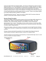
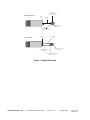
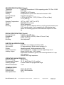
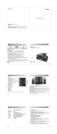
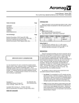
High Resolution PreView tm Operating Manual/Installation Guide
Product Description
The High Resolution PreView tm is a solid-state, pulsed radar object detection system designed
to alert vehicle operators to the presence obstacles. The system detects both moving and
stationary objects in a pre-defined coverage area and reports the distance of the closest object
via visual range indicators and an audible signal to a vehicle operator. The High Resolution
PreView tm system is designed to supplement other safety practices and is not intended to be
the sole method of collision avoidance.
The High Resolution PreView tm consists of four major components: an environmentally sealed
sensor, an operator display mounted in the cab of the vehicle, an interconnect cable, and a
recommended optional external back up warning alarm or camera system. The High
Resolution PreView tm system does not require cleaning and is not affected by harsh weather
conditions, including temperature extremes, rain, sleet, snow, or fog.
The High Resolution PreView tm system comes in three different models:
HRPV 2020
HRPV 2015
HRPV 2010
Twenty foot (6 meter) detection range
Fifteen foot (4.5 meter) detection range
Ten foot (3 meter) detection range
Sensor/Antenna Description
The antenna assembly transmits and receives low power 6.3GHz radar signals. It then
processes the returned signals to determine if an object has reflected any energy back to the
Preco Electronics, Inc.
415 N. Maple Grove, Boise, ID 83704
(800) 453-1141
Copyright 2006
Page 1 of 12
370-001-2A
sensor and reports this to the operator display. The sensor is designed to process and report
detections within ½ of a second allowing the vehicle operator to quickly respond to any object
within the detection zone. All connections to a vehicle are accomplished at the sensor. Power
is typically obtained from the vehicle reverse lights and a switched output is provided for
operating a back up alarm or camera. The connection to the display unit is through a watertight
connector eliminating any potential problems with pin corrosion. Power to the operator display
is provided through the sensor interface to the display.
The High Resolution PreView tm sensor has continuous Built In Self Test which notifies the
operator of sensor failure within a fraction of a second.
Operator Display Description
The operator display provides the vehicle operator with both visual and audible indications of a
detected object. Range to the detected object is provided with five LED’s. Each LED
represents 1/5th of the total range. Example: For the WB2015, each LED represents
approximately 3 feet (1 meter). The display unit also contains a buzzer to provide an audible
alert that will increase in rate as an object becomes closer, providing the operator with another
cue that an object is being detected.
The operator display continuously monitors communication from the High Resolution PreView
tm
sensor and in the event of a system failure or malfunction, will notify the operator with a fault
indication
A buzzer volume control switch is provided on the front panel of the display allowing the
vehicle operator the ability to adjust the buzzer volume to four different levels.
The LED indicators are automatically compensated by an internal ambient light sensor to avoid
excessive intensity in low light conditions.
Buzzer
Range Indications
5 Zones
Volume Control
Switch
Status LED
Preco Electronics, Inc.
415 N. Maple Grove, Boise, ID 83704
(800) 453-1141
Copyright 2006
Page 2 of 12
370-001-2A
Item
Status LED
Range
Indications
Buzzer
Volume Control
Switch
Description
Illuminates green continuously after power is applied to the system. The
status will change from green to red if a system malfunction occurs.
Illuminate to give operator a relative distance measurement to the closet
detected object. LED’s operate from the left to right, with a closer object
resulting in more LED’s illuminated.
Sounds audible tones to alert operator of obstacles. The buzzer tone
rate will increase as the vehicle gets closer to an object.
This momentary push button switch allows four different buzzer volume
levels to be selected. Four successive push/release cycles are needed
to cycle the buzzer through its available settings.
Table 1. Operator Display Description
Object Detection Capability
The High Resolution PreView tm system can detect most objects within the detection zone.
However, there are some instances where objects can go undetected. Obstacle size, shape,
relative location, and composition are all factors determining if, when and where an object is
detected. The PreView tm system operates by transmitting a pulse of very low power
electromagnetic energy. Any energy that strikes an object reflects a certain amount of this
energy back to the PreView tm sensor. . If the returned energy is of sufficient magnitude, it is
used to indicate object presence and determine the object’s distance. While the PreView tm
system can resolve multiple objects, only the object closest to the vehicle is reported to the
operator display since it represents the most significant collision threat
The amount of energy returned is based on a few factors:
Size – a larger object usua lly reflects more energy than a smaller object.
Composition – a metal object typically reflects more energy than a non-metallic object.
A metallic object at the edge of the maximum detection zone might be detected,
whereas a wood object may not
Scattering – a solid object reflects more energy that a non-solid object such as tree
branches, gravel, bushes, etc.
Shape – complex shapes cause energy to be returned in a very non uniform way. Very small variations or movement can change detection
status.
Angle – an object flat side perpendicular to the sensor will reflect more energy than an
object at an angle. See below for an example of how angle can affect return energy.
Preco Electronics, Inc.
415 N. Maple Grove, Boise, ID 83704
(800) 453-1141
Copyright 2006
Page 3 of 12
370-001-2A
Minimal reflection
Object surface
at A 45 degree angle to the
PreView™ sensor
PreView™
sensor
Transmitted
signal
Object in the PreView™ system
detection zone
Reflected
signal doesn’t return to the
PreView™ sensor
Full reflection
Transmitted
signal
PreView™
sensor
Reflected signal returns to the
PreView™ sensor
Object in the PreView™ system
detection zone
Object surface at a 90° degree angle to
the PreView™sensor
Figure 1. Object Reflection
Preco Electronics, Inc.
415 N. Maple Grove, Boise, ID 83704
(800) 453-1141
Copyright 2006
Page 4 of 12
370-001-2A
SENSOR SPECIFICATIONS (Typical)
Transmitter:
Pulsed RF transmitter at 6.3GHz operating under FCC Part 15.250
Electronics:
Solid state
Connector:
Conxall 72x1-8PG series
Sealing:
Encapsulated to protect from dust and moisture to IP67.
Housing Material:
Polycarbonate radome
Dimensions:
4.125”H x 4.950"W x 1.75"D (10.5cm x 12.7cm x 4.4cm)
Weight:
1.5 lb. (0.68 kg)
Operating Temperature:
Vibration:
Shock:
Mounting:
-40oF to +185oF (-40oC to +85oC)
25G RMS all three axes
25G all three axes
Four 0.22" (5.6mm) diameter holes on 4.25” horizontal centers and
2.00” vertical centers. Unit is supplied with #10 stainless steel
screws for mounting purposes. Recommended torque is 22 inchlbs.
DISPLAY SPECIFICATIONS (Typical)
Housing Material:
Polycarbonate/ABS alloy
Dimensions:
1.00”H x 2.25"W x 2.00"D (2.5cm x 5.7cm x 5.1cm)
Weight:
0.25 lb. (0.11 kg)
Mounting:
User dependent
ELECTRICAL SPECIFICATIONS
Input Voltage:
9-32VDC, over voltage protected to 150V
Input current:
0.2 amp maximum, inrush current limited to 1A
Polarity:
Negative ground, Polarity protected to 150V
Power Connection:
Two 20 AWG wires, connect to reverse signal lamp circuit
Auxiliary Output:
Single 20 AWG wire, +150V tolerant
Active State: switched to ground, over current protected to 1 amp
sink maximum.
Inactive State: high impedance
OPERATING CHARACTERISTICS
Maximum Range:
20 feet (6m)
Programmable Ranges: 10, 15, and 20 feet (3, 4.5, and 6m)
Warning Ranges:
5 zones divided into programmed range
Minimum Resolution:
1 foot
COMMUNICATION
Physical Layer:
Protocol Layer:
Data Update Rate:
Preco Electronics, Inc.
CAN 2.0B, 250 KB/s
SAE J1939 Extended
70 ms
415 N. Maple Grove, Boise, ID 83704
(800) 453-1141
Copyright 2006
Page 5 of 12
370-001-2A
MAINTENANCE
Daily: Follow test and maintenance procedure.
REGULATORY COMPLIANCE
Compliant with FCC Part 15.250 (5925-7250MHz).
FCC ID:
OXZWBPV2006
PRODUCT MANUFACTURED IN THE USA
FCC STATEMENT
This device complies with Part 15 of the FCC Rules. Operation is subject to the
following two conditions: (1) this device may not cause harmful interference, and (2)
this device must accept any interference received, including interference that may
cause undesired operation.
Warning: Changes or modifications to this unit not expressly approved by the party
responsible for compliance could void the user’s authority to operate the equipment.
Preco Electronics, Inc.
415 N. Maple Grove, Boise, ID 83704
(800) 453-1141
Copyright 2006
Page 6 of 12
370-001-2A
INSTALLATION INSTRUCTIONS
Before You Start
Prior to installing the High Resolution PreView tm Object Detection System take time to
familiarize yourself with the installation instructions, theory of operation, and system
components. Check the contents of the shipping package and verify the following items are
included:
Antenna Sensor (1)
Display Unit (1)
Interconnect Cable (1)
User Manual/Operating Instructions
Sensor Stainless Steel Mounting Hardware
(4) 1-1/4” x 10-24 Bolts
(4) Hex Locking Nuts
(4) Flat Washers
Display Mounting Hardware
Mounting Bracket
(2) #4-40 Lock Nuts
Sensor/Antenna Location
The High Resolution PreView tm sensor mounting location is key to proper system operation.
Ideally the sensor should be mounted on the rear center of the vehicle at roughly 36” (1M) +/12” (0.3M) above the ground. The sensor face should be perpendicular to the ground with the
small end of the “V” graphic on the sensor face pointing down. Select a location that will
provide some protection from impact and debris while allowing an unobstructed view of the
target hazard area.
Important!
Before the High Resolution PreView tm system is permanently installed to the vehicle, verify
that the selected sensor mounting location provides a clear detection zone. Temporarily attach
the sensor in the proposed mounting location, apply power to the system, and verifying that
nothing is being detected.
Sensor/Antenna Mounting
1. Select the appropriate sensor mounting location.
2. The standard mounting configuration is with the sensor’s stylized “V” logo pointing down.
3. Using the sensor’s mounting holes as a template, scribe position marks through the holes.
Drill 1/4” (6mm) holes centered at the marks.
4. A 1” diameter clearance hole is required for the sensor connector and mating cable
connector.
5. Secure the sensor to the vehicle with the four supplied 10-24 UNC button head screws,
washers and nuts or equivalent. Apply a maximum torque of 22 inch pounds when securing
the sensor.
Preco Electronics, Inc.
415 N. Maple Grove, Boise, ID 83704
(800) 453-1141
Copyright 2006
Page 7 of 12
370-001-2A
Sensor Power Connection
Locate the vehicles reverse light power wire and connect to the red wire on the sensor harness
using 20AWG wire minimum. Connect the black wire of the sensor harness to vehicle ground.
+
-
Red
Black
Blue
+12 VDC (Reverse Circuit)
Ground
Aux. Output
Back Up Alarm Electrical Connection
The High Resolution PreView tm sensor provides an auxiliary output that can be used to
activate an external back up alarm. The High Resolution PreView tm system activates this
output whenever an object is detected. This output is switched from a high impedance state to
ground when active and is protected against an over current condition. The maximum
operating current is approximately 1 amp which includes any inrush current. For alarms that
meet the 1 amp maximum current, connect the blue wire on the interconnect harness as
shown. For alarms that exceed the 1 amp current limit, an intermediary relay will be required
between the sensor and the alarm.
+12 VDC
+
-
The PreView
tm
PreView (Blue Wire)
NOTE:
sensor does not provide a power source for back up alarm use.
Display Unit Installation
The display unit should be mounted where the vehicle operator can easily view it while
backing. The ideal location for this is on the dash positioned by either windshield pillar. This
will allow the operator view of the display while also looking out one of the side mirrors.
The High Resolution PreView tm display unit comes equipped with a mounting bracket and
hardware. If desired, the display unit can be mounted to the display bracket with the supplied
hardware. This bracket can then be mounted in the vehicle cab as desired.
Preco Electronics, Inc.
415 N. Maple Grove, Boise, ID 83704
(800) 453-1141
Copyright 2006
Page 8 of 12
370-001-2A
Cable Installation
The interconnect cable between the sensor and display is 25 feet (7.6M) in length. If the
distance between the sensor and display is greater than 25 feet, contact Preco for additional
cable extensions.
Routing of the cable should start at the sensor. Allow for a small service loop in the cable at
the sensor and secure the cable every few feet (~1M) with tie wraps. When ready to enter the
cab, drill a 1” (24mm) hole and feed the display connector through. The remaining length of
cable is then routed to the display unit and the connectors are latched together. Care should
be taken to not route the cable next to heat sources such as the engine and exhausts and
areas that may see abrasion or rock damage.
Initial System Power Up and Test
Once the sensor and display are installed, wired, and connected, power should be applied to
test correct system operation. Upon power up, the display will go through its self-test by
illuminating all LED’s and sounding the buzzer. When the system is operating correctly in an
open field with no obstructions, the status LED indicating green will be the only light
illuminated. If any the detection (yellow) LED’s are lit, check for any vehicle obstruction which
may be detected by the sensor. If possible move the sensor so it is not detecting the object(s).
If it is not possible to relocate the sensor, then consult the factory.
If for some reason the system is malfunctioning, all of the yellow LED’s will be flashing, the
status LED will turn from green to red, and the buzzer will be sounding. Refer to the Error
Indications and Troubleshooting sections below to determine the error and solution.
Once the system has been installed, the detection zone should be tested. Testing is
accomplished by using two individuals. One individual is engages the parking brake,
depresses the vehicle brake, and places the vehicle in reverse. The other individual then
walks through the detection zone noting where the display buzzer or the back up alarm
activates. By moving about the rear of the vehicle and noting when the display or back up
alarm activate, an accurate detection zone can be mapped.
Preco Electronics, Inc.
415 N. Maple Grove, Boise, ID 83704
(800) 453-1141
Copyright 2006
Page 9 of 12
370-001-2A
COMMON INSTALLATION PROBLEMS AND TROUBLESHOOTING
TBD
Preco Electronics, Inc.
415 N. Maple Grove, Boise, ID 83704
(800) 453-1141
Copyright 2006
Page 10 of 12
370-001-2A
MANUFACTURER LIMITED WARRANTY AND LIMITATION OF LIABILITY
Manufacturer warrants that on the Date of Purchase this Product will conform to
Manufacturer's published specifications for the product, which are available from Manufacturer
on request, and Manufacturer warrants that the product is free from defects in materials and
workmanship. This Limited Warranty extends for twelve (12) months from the date of
manufacture. Manufacturer will, at its option, repair or replace any product found by
Manufacturer to be defective and subject to this Limited Warranty.
This Limited Warranty does not apply to parts or products that are misused; abused; modified;
damaged by accident, fire or other hazard; improperly installed or operated; or not maintained
in accordance with the maintenance procedures set forth in Manufacturer's Installation and
Operating Instructions.
To obtain warranty service, you must ship the product(s) to the specified Manufacturer location
within thirty (30) days from expiration of the warranty period. You must fill out the warranty
claim form and include the form with the product. You must prepay shipping charges and use
the original shipping container or equivalent. Return shipping charges within the United
States, Canada, and Puerto Rico, will be paid by Manufacturer. This Limited Warranty will
apply only to a product purchased and located in the United States, Canada, or Puerto Rico.
EXCLUSION OF OTHER WARRANTIES: MANUFACTURER MAKES NO OTHER WARRANTIES,
EXPRESSED, IMPLIED OR STATUTORY. THE IMPLIED WARRANTIES FOR MERCHANTABILITY
AND FITNESS FOR A PARTICULAR PURPOSE ARE HEREBY EXCLUDED AND SHALL NOT
APPLY TO THE PRODUCT. BUYER'S SOLE AND EXCLUSIVE REMEDY IN CONTRACT, TORT OR
UNDER ANY OTHER THEORY AGAINST MANUFACTURER RESPECTING THE PRODUCT AND
ITS USE SHALL BE THE REPLACEMENT OR REPAIR OF THE PRODUCT AS DESCRIBED ABOVE.
LIMITATION OF LIABILITY: IN THE EVENT OF LIABILITY FOR DAMAGES ARISING OUT OF THIS
LIMITED WARRANTY OR ANY OTHER CLAIM RELATED TO MANUFACTURER'S PRODUCTS,
MANUFACTURER'S LIABILITY FOR DAMAGES SHALL BE LIMITED TO THE AMOUNT PAID FOR
THE PRODUCT AT THE TIME OF ORIGINAL PURCHASE. IN NO EVENT SHALL MANUFACTURER
BE LIABLE FOR LOST PROFITS, THE COST OF SUBSTITUTE EQUIPMENT OR LABOR,
PROPERTY DAMAGE, OR OTHER SPECIAL, CONSEQUENTIAL OR INCIDENTAL DAMAGES
BASED UPON ANY CLAIM FOR BREACH OF CONTRACT, NEGLIGENCE OR OTHER CLAIM,
EVEN IF MANUFACTURER OR A MANUFACTURER'S REPRESENTATIVE HAS BEEN ADVISED OF
THE POSSIBILITY OF SUCH DAMAGES. Manufacturer shall have no further obligation or liability
with respect to the product or its sale, operation and use, and Manufacturer neither assumes
nor authorizes the assumption of any other obligation or liability in connection with such
product.
This Limited Warranty gives you specific legal rights, and you may also have other legal
rights, which vary, from state to state. Some states do not allow the exclusion or limitation of
incidental or consequential damages, so the above exclusion or limitation may not apply to
you.
Any oral statements or representations about the product, which may have been made
by salesmen or Manufacturer representatives, do not constitute warranties. This Limited
Warranty may not be amended, modified or enlarged, except by a written agreement signed by
an authorized official of Manufacturer that expressly refers to this Limited Warranty.
Preco Electronics, Inc.
415 N. Maple Grove, Boise, ID 83704
(800) 453-1141
Copyright 2006
Page 11 of 12
370-001-2A
PREVIEW tm DAILY MAINTENANCE
Detach this page and place with daily operator maintenance procedures
Safety Message to Operators of Vehicles with PreView
1.
2.
3.
4.
5.
6.
7.
tm
tm
Systems
The PreView system is intended as an Object Detection System and should not be relied upon as your first line of
defense for the safe operation of the vehicle. It should be used in conjunction with established safety programs and
procedures to augment the safe operation of the vehicle, ground personnel, and adjacent property. Should the system
become inoperative, it could jeopardize the safety or lives of those who depend on the system for safety.
Testing and inspection of the system in accordance with these instructions and record of the results should be listed on
the daily maintenance report. The units on operating vehicles must be tested each day prior to the vehicle's operation.
Results of this test must be recorded in the maintenance log.
People operating this equipment MUST check for proper operation at the beginning of every shift or safety inspection
period.
People's lives depend on the proper installation of this product in conformance with these instructions. It is necessary to
read, understand and follow all instructions shipped with the product.
Failure to follow all safety precautions and instructions may result in property damage, serious injury, or death.
tm
The PreView Object Detection System is intended for commercial use. Proper installation of a back-up aid requires a
good understanding of truck electrical systems and procedures, along with proficiency in the installation.
Store these instructions in a safe place and refer to them when maintaining and/or reinstalling the product.
Testing and Maintenance
NOTE: A walk around test shall be performed every day to verify proper function of the system and to familiarize the operator
with the zone of detection. More frequent inspections should be performed when:
The vehicle is operating in a particularly dirty or harsh environment.
The operator has reason to suspect the system has been damaged.
This test should be performed with two people, one who remains in the cab (the operator), and one who walks through the
sensor field to the rear of the vehicle (the assistant).
1.
2.
Clean the sensor face of any accumulation of dirt, mud, snow, ice, or debris.
Visually inspect the attached wiring and cable and verify that they are properly secured, not chafing or dangling free
where they could become snagged and damaged. Inspect the Radar Sensor and Operator Display Module and verify that
they are securely attached to the vehicle.
3. Set the park brakes, start the vehicle, depress and hold the vehicle brake and place the vehicle in reverse.
4. Verify the green “POWER” light is illuminated on the in-cab display.
5. The area to the rear of the vehicle should be clear of obstacles for a distance of 8 meters. If the display shows any
indicator other than the green light then there are objects to the rear of the vehicle that will interfere with the test. Move
the vehicle to a clear area and proceed.
6. The assistant should move to just behind the rear corner of the vehicle in sight of the operator's mirrors. He should then
walk toward the centerline of the vehicle parallel to the rear, noting when the external backup alarm activates, signifying
the sensor has detected him. Upon hearing the backup alarm the operator should verify all the display LED’s are lit and
the audible alarm is quickly pulsing. Note: If an external backup alarm is not connected, the operator will notice a
detection only by the display LED’s and buzzer operation and communicate the detection or lack of detection to the
assistant as the assistant moves through the area to the rear of the vehicle.
7. The assistant should continue walking through the area at the rear of the vehicle noting the area that detection occurs.
8. Now walk from the center of the rear of the vehicle straight back, away from the vehicle. When the alarm quits sounding
the detection limit has been reached.
9. Move halfway back and remain still for a few seconds, the alarm should continue to sound, demonstrating the system’s
ability to detect a still object.
10. The assistant should walk the complete rear of the vehicle noting the detection edges of the entire coverage area.
11. After the test the assistant needs to communicate to the operator the details on the detection zone.
For Questions call 1-800-453-1141 between 7:00 AM and 5:00 PM Mountain Time Zone
Preco Electronics, Inc.
415 N. Maple Grove, Boise, ID 83704
(800) 453-1141
Copyright 2006
Page 12 of 12
370-001-2A