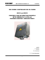
1
OLICORP
BETA VERSION DOCUMENT 0.0
10/09/2007
IRS POWER CONTROLER FOR IR. OVENS
IRS10 and IRS12
PROFIBUS AND AUTOMATION EXAMPLE
WITH OMRON PLC CJ1M and
PROFIBUS MASTER VERSION PRM21
OLICORP
Zurlinden 6
CH-1207 Genève
Switzerland
Ph : +41 22 309 15 40
Fx : +41 44 355 38 20
Local support is available WorldWide
Check on www.olicorp.ch
-1-
OLICORP
BETA VERSION DOCUMENT 0.0
10/09/2007
DOCUMENT OVERVIEW : ................................................................................................................ 3
CE relevant european directives...................................................................................................... 4
Low Voltage compliance ................................................................................................................. 4
EMC compliance ............................................................................................................................. 4
CE Label.......................................................................................................................................... 4
CSA / CUS® Marking ......................................................................................................................... 4
Profibus® standard compliance ...................................................................................................... 4
Safety and security aspects ............................................................................................................. 5
Symbols :......................................................................................................................................... 5
Safety : ............................................................................................................................................ 5
PART 1 : SETTING UP THE COMMUNICATION BETWEEN THE
OMRON PLC AND THE IRS ....................................................................6
NETWORK SETTINGS ....................................................................................................................... 7
Hardware used in the example : ..................................................................................................... 7
First Step : Installing the PLC......................................................................................................... 8
Second step : configuring the network ............................................................................................ 8
PLC SETTINGS AND DATA ACCESS : .......................................................................................... 15
Tools :............................................................................................................................................ 15
IRS Data Access from PLC :......................................................................................................... 15
Data sent from PLC to IRS :.......................................................................................................... 16
Data Sent from IRS to PLC : ......................................................................................................... 16
Turning lamps on with the Omron PLC ......................................................................................... 16
PART 2 : ELECTRICAL INTEGRATION AND AUTOMATION ................24
Standard design of the electrical power supply : ....................................................................... 25
Architecture of the automation program : .................................................................................... 26
Program example : .......................................................................................................................... 27
-2-
OLICORP
BETA VERSION DOCUMENT 0.0
10/09/2007
DOCUMENT OVERVIEW :
How to configure the
MASTER Controller
Using CX
PROFIBUS
Master Addressing
Slave GSD loading
Slave addressing
Loading the
configuration into
master
Where to find the
IRS data in the PLC
memory ?
Integrating the system
on a machine
Starting the oven
with the PLC
Setting the lamps
configuration with
OLICORP Software
and storing it into the
IRS ROM memory
Schematics of the
power supply
Automation
program
architecture
Sending the set points
to the IRS with the
PLC
CX Programmer
Prog example
Turning oven ON with
the PLC
-3-
OLICORP
BETA VERSION DOCUMENT 0.0
10/09/2007
CE relevant european directives
Low Voltage compliance
The IRS products carry the CE mark in compliance with the essential requirements of the
European Low Voltage Directive 73/23/EEC of 19/2/73, amended by the directive 93/68/EEC of
22/7/93.
The IRS products installed and used in compliance with the procedures described in the present
document meet the essential requirements of the European Low Voltage Directive.
EMC compliance
The IRS products are compliant with the EMC requirements with respect to the European
directives 89-336/EEC of the 05//03/89 amended by the 91-263/EEC, 92-31/EEC, 93-68/EEC,
93-97/EEC. The enforcement of this directives is done by standards : EN60204, EN50081-2
and EN50081-3
EM compliance has been certified by an approved EMC testing laboratory. Certificates are
available upon request.
More details about EM compliance are given later in this document.
CE Label
By fulfilling the requirements of the Low voltage and EMC regulations, the IRS products are
compliant with the CE directives.
CSA / CUS® Marking
The IRS products CSA/UL compliance has been investigated by the CSA laboratories in
Toronto, Canada. (May 2007). File number 1871799.
Profibus® standard compliance
The IRS carries the Profibus-DP compliance label and is listed by the PNO organization under
reference IRPC1012 with id number 0594Hex.
-4-
OLICORP
BETA VERSION DOCUMENT 0.0
10/09/2007
Safety and security aspects
Symbols :
This symbol means that failure to take note of the information given in this manual may have
serious consequences for the safety of the personnel or may result in electrocution.
This symbol means that failure to take note of the information given in this manual may have
serious consequences for the installation, lead to incorrect operation of the product, or may
damage the product.
Safety :
The installation, configuration, commissioning and maintenance of the IRS products must only
be carried out by personnel qualified and trained to work with low voltage electrical equipment in
an industrial environment.
The front door should not be opened except by competent technicians when connecting or
disconnecting the device. Electrical isolation must be ensured between the equipment and the
power supply.
In both off and on modes, the IRS regulator doesn’t ensure isolation from the power supply.
One should pay attention to the fact that electrical shock may occure when touching the lamps
or the cables coming from the IRS.
It is thus recommended to turn off the power supply (400 V) within 2 sec following the end of
regulation.
-5-
OLICORP
BETA VERSION DOCUMENT 0.0
10/09/2007
PART 1 : SETTING UP THE COMMUNICATION BETWEEN
THE OMRON PLC AND THE IRS
-6-
OLICORP
BETA VERSION DOCUMENT 0.0
10/09/2007
NETWORK SETTINGS
Hardware used in the example :
•
•
•
•
•
•
•
IRS 10 or 12 Firwmare 5.X
PLC Omron® CJ1M CPU 11
Master Module Omron CJ1W-PRM21®
24DC supply 350 mA for the IRS
Cable RS232 for Omron PLC programation SCY-CN217
Cable RS232 Null Modem for IRS configuration
OLICORP – Hybdrid Profibus Cable equipped with DB9 on one side for the connection
PLC-IRS Ref : WO.10.1
Diagrams for the Programming cables :
Signal
PC side
Omron PLC – SCYCN217
FG
TD
RD
RTS
CTS
SG
DSR
DTR
TYPE CONN
3
2
7
8
5
6
4
DB9 – FEMALE
3
2
5
4
9
DB 9 MALE
OLICORP IRS 10/12
(NULL MODEM)
WO10.1
2
3
8
7
5
4
6
DB 9 FEMALE
Pin out DB9 Male side
Profibus DP Cable and 24DC
supply for the IRS WO10.1
PLC programming cable.
OMRON. SCY CN217
-7-
OLICORP
BETA VERSION DOCUMENT 0.0
10/09/2007
First Step : Installing the PLC
The PLC and PRM21 Master must be set according to Omron Spec.
In our example, PRM21 is set as Slot ID = 0 using the wheel on the front.
The IRS is connected to the PRM21 via a profibus cable.
Reminder : If it necessary to build a specific Profibus cable the pin out on the master is the
following :
Pin 8 : Channel A Green cable
Pin 3 : Channel B Red Cable
At the first boot the ERC led of the PRM21 master will turn red because the PLC and Master
have not been configured yet.
Second step : configuring the network
The purpose of this step is to send the required information about the network structure to the
PLC.
- Type of Master
- List of slaves present on the network and their associated protocols.
- Profibus addresses of master and slaves
To do so, we use the OMRON CX PROFIBUS 1.0 software which will transfer this information
the master module through the PLC.
See the following pictures to follow the configuration process :
A. Import OLICORP GSD file in the system :
-8-
OLICORP
BETA VERSION DOCUMENT 0.0
B : Configure the Network :
Use the Add device command to add the PLC
-9-
10/09/2007
OLICORP
BETA VERSION DOCUMENT 0.0
The configuration command is used to configure the PLC :
- 10 -
10/09/2007
OLICORP
BETA VERSION DOCUMENT 0.0
10/09/2007
In the configuration Panel it is necessary to check the following information
- version for the PLC CPU (here CJM1 11)
- Which COM interface to use to connect to the Master through the CPU (here 5)
- 11 -
OLICORP
BETA VERSION DOCUMENT 0.0
10/09/2007
The Slaves must be added the same way.
For each IRS slave it is necessary to configure the Profibus DP address (must be the same on
the wheels in the IRS cabinet, and on the Profibus Configurator).
A specific protocol must be selected for each slave.
- 12 -
OLICORP
BETA VERSION DOCUMENT 0.0
10/09/2007
The system automatically associate the input / Output datagram with a specific CIO address in
the PLC memory.
When writing the automation program
in the next step, one will have to refer
to the content of these addresses to
exchange data with the IRS system
See technical documentation of IRS
to find the description of the
datagrams
- 13 -
OLICORP
BETA VERSION DOCUMENT 0.0
10/09/2007
At this point, it is possible to Download the configuration to the PLC and the master using the
download command.
The process is finished.
All LEDs should be green :
-
on Master PRM21, the ERC turns to green. The BF may be orange if there is a missing
component on the network.
On the IRS the Profibus Green LED should turn green.
If NOT :
-
Try to reboot PLC and IRS
Check cabling
Check Profibus Adresses
Reload configuration
- 14 -
OLICORP
BETA VERSION DOCUMENT 0.0
10/09/2007
PLC SETTINGS AND DATA ACCESS :
Tools :
For the automation programming we are using :
-
CX programmer OMRON Version 7.0
OLICORP Supervisor 10.1 to cross check the information sent to the IRS by the PLC and to
store the lamps configuration and running options in the IRS.
IRS Data Access from PLC :
When setting the network we have selected the following information :
-
PLC MASTER is on slot 0.
PLC Master has profibus ID 1
IRS Slave is connected to the Master and has Notwork ID : 5
IRS uses the IRSPWR_STD_SHORT protocol.
The Profibus Configurator program from OMRON has given the following information to us :
-
The output datagram is 13 words long and has 1 word from address 3200 and 12 words
from address 3201
The input datagram is 5 words long and starts at address CIO 3300
By using the protocol description in IRS technical manual it is possible to associate this
information with the basic parameters to be sent or received to/from the Irs.
NOTE THAT HIGH AND LOW ORDER BYTES IN WORDS ARE INVERTED IN PLCs WITH
RESPECT TO MOTOROLA 32b PROCESSORS.
So on the PLC bits 8-15 correspond to Byte 0 of IRS
And bits 0-7 correspond to Byte 1 of IRS
- 15 -
OLICORP
BETA VERSION DOCUMENT 0.0
10/09/2007
Data sent from PLC to IRS :
IRS Byte 0
PLC Byte 1
CIO 15
3200 3201
3202
3203
3204
3205
3206
3207
3208
3209
3210
3211
3212
14
-
13
-
IRS Byte 1
PLC Byte 0
12
11
ON/OFF -
10
-
9
8
7
6
POWER LAMP 1
POWER LAMP 2
POWER LAMP 3
POWER LAMP 4
POWER LAMP 5
POWER LAMP 6
POWER LAMP 7
POWER LAMP 8
POWER LAMP 9
POWER LAMP 10
POWER LAMP 11
POWER LAMP 12
5
-
4
-
3
-
2
-
1
-
0
-
Data Sent from IRS to PLC :
CIO
3300
3301
3302
3303
3304
15
SD
PNR1
DL1
14
OH
PNR2
DL2
13
CO
PNR3
DL3
12
OV
PNR4
DL4
11
OL
PNR5
DL5
10
PNR6
DL6
9
PNR7
DL7
8
PNR8
DL8
7
PNR9
DL9
6
PNR10
DL10
5
PNR11
DL11
4
3 2 1 0
- - - PNR12
DL12
Square ( Vrms)
SD : Supply default
OH : Overheat
CO : Cut Out
OV : Oven On
OL : Overload
PNR : Power nor reached
DL : Dead Lamp
V : Vrms2
At this point, the communication between the IRS and the PLC is effective and one can easily
use these data areas to control the IRS from the PLC.
Testing the IRS control with the Omron PLC
In this example it has been decided to use the IRSPWR_STD_SHORT protocol.
Using the SHORT version of the protocol is a great simplification for the PLC program, but it
requires a pre-configuration of the IRS to store permanently the lamps configuration in the
ROM memory of the IRS.
- 16 -
OLICORP
BETA VERSION DOCUMENT 0.0
10/09/2007
STEP 1 :
Storing the lamps configuration in the IRS using the SUPERVISOR or PWR24COM programs.
-
Connect a PC were SUPERVISOR program is running to the IRS using the null modem
cable.
Start the SUPERVISOR and go to hardware settings menu.
Set the lamps voltage and nominal power and save it by clicking update.
Reboot the IRS.
Note : During this step, one can also configure the running modes and options of the IRS. For
more information refer to SUPERVISOR user’s manual.
Voltage and nominal
power of the lamps.
Click update to save to
ROM Memory
- 17 -
BETA VERSION DOCUMENT 0.0
10/09/2007
- 18 -
Left PLC prog view
No setting – No 400 V - No
command
To ease the debugging process, we suggest to disconnect the oven to receive Dead lamp signals and thus to verify the position of each dead lamp bit
in the PLC memory.
Sending the set points to the IRS from the PLC.
STEP 2 :
OLICORP
OLICORP
Oven ON =
3200.12
1
- 19 -
BETA VERSION DOCUMENT 0.0
Oven ON – No 400 V– No
setting => Sector Default
10/09/2007
PLC
3300.15 = 1
Supply faulty
IRS
OLICORP
- 20 -
BETA VERSION DOCUMENT 0.0
10/09/2007
Turning oven off will reset the default.
OLICORP
- 21 -
BETA VERSION DOCUMENT 0.0
Supervisor and PLC show ON STATE
for OVEN
No Alarm.
Turn ing Oven on with 400 On.
10/09/2007
OLICORP
- 22 -
BETA VERSION DOCUMENT 0.0
No lamp is connected the IRS sends a Power not
reached and Dead lamp alarm.
Send Set point to lamp 1 : 500 W .
10/09/2007
OLICORP
- 23 -
BETA VERSION DOCUMENT 0.0
No lamp is connected the IRS sends a Power not
reached and Dead lamp alarm.
Turning on lamp 6 and 11.
10/09/2007
OLICORP
BETA VERSION DOCUMENT 0.0
10/09/2007
PART 2 : ELECTRICAL INTEGRATION AND AUTOMATION
- 24 -
OLICORP
BETA VERSION DOCUMENT 0.0
Standard design of the electrical power supply :
+24V
Main switch of the machine
+24V
AC
PLC
(mcu)
+24V
Digital
Input
Digital
output
24VDC
0V
+24V
Breaker
Contactor
+24V
R
PWR or IRS
PWR or IRS
PWR or IRS
Oven (up to 10 Lamps)
Oven (up to 10 Lamps)
Oven (up to 10 Lamps)
www.olicorp.ch
- 25 -
10/09/2007
OLICORP
BETA VERSION DOCUMENT 0.0
Architecture of the automation program :
- 26 -
10/09/2007
OLICORP
BETA VERSION DOCUMENT 0.0
Program example :
- 27 -
10/09/2007