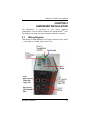
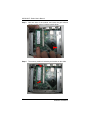
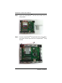
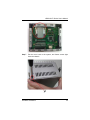
1
rBOX100-FL Series Robust Din-rail Fanless Embedded System User’s Manual Disclaimers This manual has been carefully checked and believed to contain accurate information. Axiomtek Co., Ltd. assumes no responsibility for any infringements of patents or any third party’s rights, and any liability arising from such use. Axiomtek does not warrant or assume any legal liability or responsibility for the accuracy, completeness or usefulness of any information in this document. Axiomtek does not make any commitment to update the information in this manual. Axiomtek reserves the right to change or revise this document and/or product at any time without notice. No part of this document may be reproduced, stored in a retrieval system, or transmitted, in any form or by any means, electronic, mechanical, photocopying, recording, or otherwise, without the prior written permission of Axiomtek Co., Ltd. Copyright 2012 Axiomtek Co., Ltd. All Rights Reserved May 2012, Version A3 Printed in Taiwan ii Safety Precautions Before getting started, please read the following important safety precautions. 1. The rBOX100-FL does not come equipped with an operating system. An operating system must be loaded first before installing any software into the computer. 2. Be sure to ground yourself to prevent static charge when installing the internal components. Use a grounding wrist strap and place all electronic components in any static-shielded devices. Most electronic components are sensitive to static electrical charge. 3. Disconnect the power cord from the rBOX100-FL before making any installation. Be sure both the system and the external devices are turned OFF. Sudden surge of power could ruin sensitive components. Make sure the rBOX100-FL is properly grounded. 4. Make sure the voltage of the power source is correct before connecting the equipment to the power outlet. 5. Turn OFF the system power before cleaning. Clean the system using a cloth only. Do not spray any liquid cleaner directly onto the screen. 6. Do not leave this equipment in an uncontrolled environment where the storage temperature is below -45℃ or above 85℃. It may damage the equipment. 7. Do not open the system’s back cover. If opening the cover for maintenance is a must, only a trained technician is allowed to do so. Integrated circuits on computer boards are sensitive to static electricity. To avoid damaging chips from electrostatic discharge, observe the following precautions: Before handling a board or integrated circuit, touch an unpainted portion of the system unit chassis for a few seconds. This will help to discharge any static electricity on your body. When handling boards and components, wear a wristgrounding strap, available from most electronic component stores. iii Classification 1. 2. 3. 4. 5. Degree of production against electric shock: not classified Degree of protection against the ingress of water: IP30 Equipment not suitable for use in the presence of a flammable anesthetic mixture with air or with oxygen or nitrous oxide. Mode of operation: Continuous Type of protection against electric shock: Class I equipment General Cleaning Tips You may need the following precautions before you begin to clean the computer. When you clean any single part or component for the computer, please read and understand the details below fully. When you need to clean the device, please rub it with a piece of dry cloth. 1. Be cautious of the tiny removable components when you use a vacuum cleaner to absorb the dirt on the floor. 2. Turn the system off before you start to clean up the component or computer. 3. Never drop the components inside the computer or get circuit board damp or wet. 4. Be cautious of all kinds of cleaning solvents or chemicals when you use it for the sake of cleaning. Some individuals may be allergic to the ingredients. 5. Try not to put any food, drink or cigarette around the computer. Cleaning Tools: Although many companies have created products to help improve the process of cleaning your computer and peripherals users can also use household items to clean their computers and peripherals. Below is a listing of items you may need or want to use while cleaning your computer or computer peripherals. Keep in mind that some components in your computer may only be able to be cleaned using a product designed for cleaning that component, if this is the case it will be mentioned in the cleaning. iv Cloth: A piece of cloth is the best tool to use when rubbing up a component. Although paper towels or tissues can be used on most hardware as well, we still recommend you to rub it with a piece of cloth. Water or rubbing alcohol: You may moisten a piece of cloth a bit with some water or rubbing alcohol and rub it on the computer. Unknown solvents may be harmful to the plastics parts. Vacuum cleaner: Absorb the dust, dirt, hair, cigarette particles, and other particles out of a computer can be one of the best methods of cleaning a computer. Over time these items can restrict the airflow in a computer and cause circuitry to corrode. Cotton swabs: Cotton swaps moistened with rubbing alcohol or water are excellent tools for wiping hard to reach areas in your keyboard, mouse, and other locations. Foam swabs: Whenever possible it is better to use lint free swabs such as foam swabs. Note We strongly recommended that you should shut down the system before you start to clean any single components. Please follow the steps below: 1. Close all application programs 2. Close operating software 3. Turn off power 4. Remove all device 5. Pull out power cable v Scrap Computer Recycling If the computer equipments need the maintenance or are beyond repair, we strongly recommended that you should inform your Axiomtek distributor as soon as possible for the suitable solution. For the computers that are no longer useful or no longer working well, please contact your Axiomtek distributor for recycling and we will make the proper arrangement. Trademarks Acknowledgments Axiomtek is a trademark of Axiomtek Co., Ltd. IBM, PC/AT, PS/2, VGA are trademarks of International Business Machines Corporation. ® ® Intel and Pentium are registered trademarks of Intel Corporation. MS-DOS, Microsoft C and QuickBASIC are trademarks of Microsoft Corporation. VIA is a trademark of VIA Technologies, Inc. SST is a trademark of Silicon Storage Technology, Inc. UMC is a trademark of United Microelectronics Corporation. Other brand names and trademarks are the properties and registered brands of their respective owners. vi Table of Contents Disclaimers .................................................................................... ii Safety Precautions ........................................................................ iii Classification................................................................................. iv General Cleaning Tips .................................................................. iv Scrap Computer Recycling ........................................................... vi CHAPTER 1 1.1 1.2 1.2.1 1.2.2 1.2.3 1.2.4 1.2.5 1.2.6 1.2.7 1.2.8 1.2.9 1.2.10 1.2.11 1.2.12 1.2.13 1.2.14 1.2.15 1.2.16 1.2.17 1.2.18 1.2.19 1.2.20 1.2.21 1.2.22 1.2.23 1.2.24 1.3 1.4 1.5 NTRODUCTION 1 General Description .................................................... 1 System Specifications ................................................. 4 CPU ............................................................................ 4 Chipset ...................................................................... 4 BIOS............................................................................ 4 System Memory .......................................................... 4 Graphics Chip ............................................................. 4 Video Memory ............................................................. 5 LAN ............................................................................. 5 Storage........................................................................ 6 USB ............................................................................. 7 COM ......................................................................... 10 Power ........................................................................ 13 WatchDog Timer (WDT)........................................... 14 Digital I/O Connector and Pin Definition ................... 17 System LED .............................................................. 23 Alarm Contact ........................................................... 32 Reset Bottom ............................................................ 40 Field Wiring Terminal................................................ 40 For use in Pollution Degree 2 Environment .............. 40 Operation Temperature ............................................ 40 Storage Temperature ............................................... 41 Humidity .................................................................... 41 Weight ...................................................................... 41 Dimensions ............................................................... 41 System I/O Outlet ..................................................... 41 Dimensions ............................................................... 42 I/O Outlets ................................................................. 43 Packing List ............................................................... 45 CHAPTER 2 HARDWARE INSTALLATION…………………………47 2.1 Wiring Diagram ......................................................... 47 vii 2.2 2.3 2.4 2.5 2.6 CHAPTER 3 3.1 3.2 3.3 3.4 3.5 3.6 3.7 3.8 3.9 3.10 3.11 3.12 3.13 3.14 3.15 Installing the Memory Module ................................... 48 Installing the CompactFlashTM Card........................ 52 Installing Din-rail Monting .......................................... 57 Setting up rBOX by Din-rail mounting ....................... 63 Installing Wall Mounting (optional) ............................ 66 PHOENIX-AWARD BIOS UTILITY……………………69 Entering Setup .......................................................... 69 Control Keys .............................................................. 69 Getting Help .............................................................. 70 The Main Menu ......................................................... 71 Standard CMOS Setup Menu ................................... 72 Advanced BIOS Features ......................................... 74 Advanced Chipset Features ...................................... 83 Integrated Peripherals ............................................... 86 Power Management Setup........................................ 96 PnP/PCI Configuration Setup.................................... 97 PC Health Status..................................................... 103 Load Optimized Defaults ......................................... 104 Set Supervisor/User Password ............................... 105 Save & Exit Setup ................................................... 107 Exit Without Saving ................................................. 108 CHAPTER 4 INSTALLATION OF DRIVERS .............................. 109 4.1 Installation Of LAN Driver Update ........................... 109 4.2 Notice For Installation Of Driver .............................. 121 viii rBOX100-FL Series User’s Manual CHAPTER 1 INTRODUCTION This chapter contains general information and detailed specifications of the rBOX100-FL. The Chapter 1 includes the following sections: 1.1 General Description System Specification Dimensions I/O Outlets Package List General Description The rBOX100-FL Din-rail fanless embedded systems are suitable for communications control and for protocol converter applications in critical environments. Built for rugged work environments, the rBOX100-FL series features an extra low ® power consumption Intel ATOM™ Z510PT (1.1 GHz) or Z520PT (1.33 GHz) processors supporting industrial temperature range of -40℃ to +70℃. Their front accessible I/O cabling is very convenient for wiring and maintenance. The rBOX100-FL series offers a VGA output, making it particularly well-suited for communication control, SCADA and industrial automation. Its compact size with Din-rail mounting allows for easy installation into control cabinet. Pre-installed with Linux, Windows ® CE 6.0. Windows ® 7 embedded or Windows ® XP embedded, the rBOX100-FL series provides programmers with a friendly environment for developing application software at a lower cost. Introduction 1 rBOX100-FL Series User’s Manual The rBOX100-FL is robust industrial-grade hardware design and adopts the advanced cooling system, besides, supporting the CompactFlash™, which makes it especially suitable for field control & monitoring system solution for following markets: Utility Industries (Water; Energy; Chemical Plant; Mining…) Public Transportation Industries (Traffic/ Highway Control; Train/Bus Control …) Homeland Security (Weather Monitoring/Alarm System …) Features 1. Fanless and no internal cabling design 2. Wide temperature operation of -40℃ - +70℃ 3. 1 DIO (8 IN/OUT) 4. Supports 2 Ethernets with Magnetic Isolation Protection 5. 2 Watchdog Timers 6. LED Indicators (Power, Alarm, Ready/Active, COM (TXD,RXD) ) 7. SNMP V1/V2c 8. Support one CompactFlash™ 9. 2 power paths with terminal block and 12–48VDC 10. Field Wiring Terminal: Use Copper Conductors Only, 12-24 AWG torque value 7 lb-in 11. For use in Pollution Degree 2 Environment 12. Din-rail mounting 13. Wall mounting (optional) 14. Passed safety agency requirements (UL508, EN60950, IEC60950) & passed heavy industrial EMI/EMS testing (ex: EN61000-6, EN61000-4, …) 2 Introduction rBOX100-FL Series User’s Manual Embedded O.S. Supported The rBOX100-FL not only supports Windows ® XP, but also supports embedded OS, such as Windows ® ® XP ® embedded, Windows 7 embedded, Windows CE 6.0 and Linux. For storage device, the rBOX100-FL supports one type II CompactFlash™ slot. Intelligent AXView & SNMP V1/V2c The rBOX100 features SNMP V1/V2c support for secured network management. To streamline implementation of management applications, Axiomtek has launched exclusive “AXView” monitoring software package for customers to build their own management systems easily and quickly. Axiomtek AXView also contains a variety of easy-to-use management utilities, agent services and libraries. For more product information, please visit our global website on Axiomtek AXView http://axiomtek.com/products/ViewProduct.asp?ptype3=268&pos =1&ptype2=229&ptype1=209 Introduction 3 rBOX100-FL Series User’s Manual 1.2 1.2.1 System Specifications CPU ® Onboard Intel Z520PT (1.33 400/533MHz. 1.2.2 Chipset Intel System Controller Hub US15WPT BIOS Phoenix AwardBIOS 1.2.3 1.2.4 System Memory 1.2.5 4 ATOM™ Z510PT (1.1 GHz) or GHz) processors with FSB One 200-pin SO-DIMM support DDR2 400/533MHz max. up to 2GB Graphics Chip Intel GMA500 graphics Core integrate in US15W PT DB15 VGA port VGA IO Pin Define : Pin Signal Pin Signal Pin Signal 1 Red 2 Green 3 Blue 4 N.C. 5 GND 6 DETECT 7 GND 8 GND 9 VCC 10 GND 11 N.C. 12 DDC DATA 13 Horizontal Sync 14 Vertical Sync 15 DDC CLK Introduction rBOX100-FL Series User’s Manual 1.2.6 Video Memory 1.2.7 Share Memory max. up to 256MB LAN LAN 1 : . GBE Intel 82574, 10/100/1000Mbps LAN w/ Magnetic Isolation Protection 1.5KV . LED definition: Active LED (Yellow flashing), 10 LAN LED (NO Light), 100 LAN LED (Green Light), 1000 LAN LED (Orange Light) LAN 2 : . FE Davicom DM9102HI, 10/100Mbps LAN w/Magnetic Isolation Protection 1.5KV . LED definition: Active LED (Yellow flashing), 10 LAN LED (NO Light), 100 LAN LED (Green Light) LAN Pin Define : FE(10M/100M) Pin Signal 1 Tx+(Data transmission positive) 2 Tx-(Data transmission negative) 3 Rx+(Data reception positive) 4 RJ45 termination 5 RJ45 termination 6 Rx- (Data reception negative) 7 RJ45 termination 8 RJ45 termination A Active LED(Yellow) B 100 LAN LED(Green) Introduction A B 87654321 5 rBOX100-FL Series User’s Manual GbE(10M/100M/1000M) Pin Signal 1 MDI0+ 2 MDI0- 3 MDI1+ 4 MDI1- 5 MDI2+ 6 MDI2- 7 MDI3+ 8 MDI3- A Active LED (Yellow) B 100 LAN LED (Green)/ 1000 LAN LED (Orange) 1.2.8 B 87654321 Storage 6 A 1 x CompactFlash TypeII Introduction rBOX100-FL Series User’s Manual 1.2.9 USB 2 x USB2.0 With power distribution control and over current protection USB Pin Define : Signal USB Port 0 Pin USB VCC (+5V level) 5 2 USB #0_D- 6 USB #1_D- 3 USB #0_D+ 7 USB #1_D+ 4 Ground (GND) 8 Ground (GND) Pin 1 Signal USB Port 1 USB VCC (+5V level) 5 6 7 8 1 2 3 4 USB power (5V) distribution control. Some program and sample code for USB power distribution control are offered in Windows and Linux. - Windows : Please refer it from our Axiomtek AXView which on Axiomtek’s website directly. - Linux : Please refer it from our Axiomtek’s website directly. Introduction 7 rBOX100-FL Series User’s Manual Axiomtek’s website for AXView : http://axiomtek.com/products/ViewProduct.asp?ptype3=268&pos =1&ptype2=229&ptype1=209 AXView Version Sample Code C (or C#) AXView 8 Introduction rBOX100-FL Series User’s Manual Axiomtek’s website for Linux : http://axiomtek.com/products/ViewDownload.asp?View=813 USB Power Distribution Control Sample code: Windows: \rBOX100-FL\AXView Version 2.7.2\Sample code\c\AXView\SetUSBPowerDisable\AXVIEW_DLL_Test.cpp Linux: \rBox100-bsp-user-1.0.0\rbox100\src\librb100.c int _rb201_usb_power(int number, int onoff) NOTE: The updated latest version of AXView and Linux will be released on Axiomtek’s global website directly. Introduction 9 rBOX100-FL Series User’s Manual 1.2.10 COM 2 ports DB9 Pin Define RS-232/422/485 ESD Protection 15KV Magnetic Isolation Protection 2KV COM1,COM2 speed up to 115.2kbps rBOX support jumper less design. All of the com port interface RS232/422/485 can be selected by BIOS menu or software program. It also supports Auto Flow Control in RS485 mode Serial Port Pin Define : (DB9 Male) rBOX100 COM1/COM2 Pin RS-232 RS-422 RS-485 1 DCD TX- Data- 2 RXD TX+ Data+ 3 TXD RX+ -- 4 DTR RX- -- 5 Ground Ground Ground 6 DSR -- -- 7 RTS -- -- 8 CTS -- -- 9 RI -- -- Some program and sample code for COM port interface type are offered in Windows and Linux. - Windows : Please refer it from our Axiomtek AXView which on Axiomtek’s website directly. - Linux : Please refer it from our Axiomtek’s website directly. 10 Introduction rBOX100-FL Series User’s Manual Axiomtek’s website for AXView : http://axiomtek.com/products/ViewProduct.asp?ptype3=268&pos =1&ptype2=229&ptype1=209 AXView Version Sample Code C (or C#) AXView Introduction 11 rBOX100-FL Series User’s Manual Axiomtek’s website for Linux : http://axiomtek.com/products/ViewDownload.asp?View=813 COM port interface selection Sample Code : -Set COM port interface type(Windows, Linux) Windows: -RS232/422/485 interface selection: rBOX Series\rBOX100-FL\AXView Version 2.7.2\Sample code\c\AXView\SetComPort\ AXVIEW_DLL_Test.cpp 12 Introduction rBOX100-FL Series User’s Manual Linux: -RS232/422/485 interface selection: \rBox100-bsp-user-1.0.0\rbox100\src\librb100.c int _rb201_set_comport(int number, int type) NOTE: The updated latest version of AXView and Linux will be released on Axiomtek’s global website directly. 1.2.11 Power 2 power paths 2 power sources must be same voltage and DC input range 12-48V. Main power source is for Input Power Path 1, Backup power source is for Input Power Path 2. Only one power source must be for Input Power Path 1. DC Input has UVP/OVP/Reverse protection. Reset Button without Power Switch DC Terminal Block Introduction 13 rBOX100-FL Series User’s Manual Pin DC Signal Name 1 AL- 2 AL+ 3 SG 4 SG 5 GND 6 DC2 7 GND 8 DC1 NOTE If 2 power sources aren’t same voltage and the system will be possible damage. NOTE When the system is shoutdown after, if users press the Reset Button for 3 seconds and the system will be restarted. 1.2.12 WatchDog Timer (WDT) rBox support two Watchdog timers. Those can cause system reset when timer expired. WDT 1 : one step is 1sec, 255 levels WDT 2 : one step is 250ms, 255 levels Some program and sample code for two Watchdog timers are offered in Windows and Linux. - Windows : Please refer it from our Axiomtek AXView which on Axiomtek’s website directly. - Linux : Please refer it from our Axiomtek’s website directly. 14 Introduction rBOX100-FL Series User’s Manual Axiomtek’s website for AXView : http://axiomtek.com/products/ViewProduct.asp?ptype3=268&pos =1&ptype2=229&ptype1=209 AXView Version Sample Code C (or C#) AXView Introduction 15 rBOX100-FL Series User’s Manual Axiomtek’s website for Linux : http://axiomtek.com/products/ViewDownload.asp?View=813 Watch Dog Timer Sample code: -Super IO(Linux) -CPLD(Windows, Linux) Windows: -CPLD: \rBOX100-FL\AXView Version 2.7.2\Sample code\c\AXView\SetWatchDog\ AXVIEW_DLL_Test.cpp 16 Introduction rBOX100-FL Series User’s Manual Linux: \rBox100-bsp-user-1.0.0\rbox100\src\librb100.c -Super IO: int _rm820_WDT_enable(unsigned char scale, unsigned char timeout) int _rm820_WDT_disable(void) int _rm820_WDT_reload(void) int _rm820_read_WDT_config(unsigned int *time) -CPLD: unsigned char _rb201_get_WDT_value(void) int _rb201_WDT_enable(unsigned char timeout) int _rb201_WDT_disable(void) NOTE : The updated latest version of AXView and Linux will be released on Axiomtek’s global website directly. 1.2.13 Digital I/O Connector and Pin Definition 8bit DI and 8bit DO DIO Design Specification DI : Input range : 0~30 VDC Logic level 0 : +/- 3V max. Logic level 1 : +/- 10V min. (COM to DI) 3KV optical isolation DO : Max. 200 mA per channel, current sink type 24VDC nominal, open collector to 30V 3KV optical isolation Some program and sample code for DIO are offered in Windows and Linux. - Windows : Please refer it from our Axiomtek AXView which on Axiomtek’s website directly. - Linux : Please refer it from our Axiomtek’s website directly. Introduction 17 rBOX100-FL Series User’s Manual Axiomtek’s website for AXView : http://axiomtek.com/products/ViewProduct.asp?ptype3=268&pos =1&ptype2=229&ptype1=209 AXView Version Sample Code C (or C#) AXView 18 Introduction rBOX100-FL Series User’s Manual Axiomtek’s website for Linux : http://axiomtek.com/products/ViewDownload.asp?View=813 GPIO control DI: - Get the DI register(Windows, Linux) - Set DI polarity(Windows) DO: - Get DO register(Linux) - Set DO register(Windows, Linux) Introduction 19 rBOX100-FL Series User’s Manual DI/DO Sample Code : Windows: -Set DI polarity: \rBOX Series\rBOX100-FL\AXView Version 2.7.2\Sample code\c\AXView\SetDIInverte\ AXVIEW_DLL_Test.cpp -Get DI: \rBOX Series\rBOX100-FL\AXView Version 2.7.2\Sample code\c\AXView\GetDi\ AXVIEW_DLL_Test.cpp -Set DO: \rBOX100-FL\AXView Version 2.7.2\Sample code\c\AXView\SetDO\ AXVIEW_DLL_Test.cpp Linux: \rBox100-bsp-user-1.0.0\rbox100\src\librb100.c -Get DI: int _ax93610_read_DI(unsigned char *data) -Get DO: int _ax93610_read_DO(unsigned char *data) -Set DO: int _ax93610_write_DO(unsigned char data) NOTE: The updated latest version of AXView and Linux will be released on Axiomtek’s global website directly. 20 Introduction rBOX100-FL Series User’s Manual DIO 8 in/out of TB25 Female rBOX100 DIO Terminal Block Pin Signal Pin Signal 1 XINCOM+ 2 XIN00 3 XIN02 4 XIN04 5 XIN06 6 NC 7 NC 8 NC 9 XOUT06 10 XOUT04 11 XOUT02 12 XOUT00 13 XOUTCOM+ 14 NC 15 XIN01 16 XIN03 17 XIN05 18 XIN07 19 NC 20 NC 21 XOUT07 22 XOUT05 23 XOUT03 24 XOUT01 25 XOUTCOM- Remark : Introduction 21 rBOX100-FL Series User’s Manual 22 rBOX100 How to control /program the I/O Introduction rBOX100-FL Series User’s Manual 1.2.14 System LED For maintenance issue, IO board will have below LED. 1. DC PWR1 : Green 2. DC PWR2 : Green 3. Alarm : Red 4. OS Ready : Yellow 5. COM TX1 : Green 6. COM RX1 : Green 7. COM TX2 : Green 8. COM RX2 : Green LED Name Description Color DC PWR1 Indicate the DC1 input status. When the DC input is acceptable, the LED will ON. Green DC PWR2 Indicate the DC2 input status. When the DC input is acceptable, the LED will ON. Green Alarm The LED will ON if having below condition. 1. DC PWR1 or PWR2 is lost. (default) 2. User define event. The behavior of Alarm and Relay are the same. When the LED of Alarm is ON and the Relay will be turn on at the same time. Red Introduction Note 23 rBOX100-FL Series User’s Manual LED Name Description Color RDY/ACT The LED for RDY/ACT can help users to judge BIOS finish or not and the OS can normal work or not. When the BIOS finish the configuration of system, the LED will ON. After this the LED will flash when the storage is accessed. - The LED will flash when the storage is accessed. - The LED always ON without any flash for a long time, the OS is possible crashed. - The LED isn’t ON for a long time, it means the system is on shutdown status. Yellow COM TX1 When COM1 transmit data the LED will on. Green COM RX1 When COM1 receive data the LED will on. Green COM TX2 When COM2 transmit data the LED will on. Green COM RX2 When COM2 receive data the LED will on. Green NOTE 24 Note When the system is shoutdown after, if users press the Reset Button for 3 seconds and the system will be restarded. Introduction rBOX100-FL Series User’s Manual Some program and sample code for Alarm LED and Relay Output are offered in Windows and Linux. - Windows : Please refer it from our Axiomtek AXView which on Axiomtek’s website directly. - Linux : Please refer it from our Axiomtek’s website directly. Alarm LED and Relay output Sample Code: - Set Alarm LED and Relay status(Windows, Linux) - Get Alarm LED and Relay status(Windows, Linux) - Get Power status( Windows, Linux) Windows: -Get the LED status: rBOX100-FL\AXView Version 2.7.2\Sample code\c\AXView\GetLEDStatus\AXVIEW_DLL_Test.cpp -Set the LED status: rBOX100-FL\AXView Version 2.7.2\Sample code\c\AXView\SetLED\AXVIEW_DLL_Test.cpp -Get Power Status: rBOX100-FL\AXView Version 2.7.2\Sample code\c\AXView\GetPowerSattus\ AXVIEW_DLL_Test.cpp Linux: \rBox100-bsp-user-1.0.0\rbox100\src\librb100.c -Get the LED status: int _rb201_get_power_usr_alarm_status(void) -Set the LED status: int _rb201_power_alarm_ctl(int onoff) -Get Power Status: int _rb201_read_power_status(int number) Introduction 25 rBOX100-FL Series User’s Manual Axiomtek’s website for AXView : http://axiomtek.com/products/ViewProduct.asp?ptype3=268&pos =1&ptype2=229&ptype1=209 AXView Version Sample Code C (or C#) AXView 26 Introduction rBOX100-FL Series User’s Manual Axiomtek’s website for Linux : http://axiomtek.com/products/ViewDownload.asp?View=813 NOTE: The updated latest version of AXView and Linux will be released on Axiomtek’s global website directly. Introduction 27 rBOX100-FL Series User’s Manual Below pictures are the LED example: 28 Introduction rBOX100-FL Series User’s Manual Introduction 29 rBOX100-FL Series User’s Manual 30 Introduction rBOX100-FL Series User’s Manual Introduction 31 rBOX100-FL Series User’s Manual 1.2.15 Alarm Contact The rBox can support two DC power source. When lost one of them will cause Alarm LED on and trigger Relay out for remote notice. We also provide the register for user to define their event for trigger the Alarm LED and Relay. Alarm LED and Relay output have the same activity depend on DC status and register control. 1 relay output Relay output with 0.5A @ 30VDC Event : Power Fail and User define Some program and sample code for Alarm LED and Relay Output are offered in Windows and Linux. - Windows : Please refer it from our Axiomtek AXView which on Axiomtek’s website directly. - Linux : Please refer it from our Axiomtek’s website directly. 32 Introduction rBOX100-FL Series User’s Manual Axiomtek’s website for AXView : http://axiomtek.com/products/ViewProduct.asp?ptype3=268&pos =1&ptype2=229&ptype1=209 AXView Version Sample Code C (or C#) AXView Introduction 33 rBOX100-FL Series User’s Manual Axiomtek’s website for Linux : http://axiomtek.com/products/ViewDownload.asp?View=813 NOTE : The updated latest version of AXView and Linux will be released on Axiomtek’s global website directly. 34 Introduction rBOX100-FL Series User’s Manual Alarm LED and Relay output Sample Code: - Set Alarm LED and Relay status(Windows, Linux) - Get Alarm LED and Relay status(Windows, Linux) - Get Power status( Windows, Linux) Windows: -Get the LED status: rBOX100-FL\AXView Version 2.7.2\Sample code\c\AXView\GetLEDStatus\AXVIEW_DLL_Test.cpp -Set the LED status: rBOX100-FL\AXView Version 2.7.2\Sample code\c\AXView\SetLED\AXVIEW_DLL_Test.cpp -Get Power Status: rBOX100-FL\AXView Version 2.7.2\Sample code\c\AXView\GetPowerSattus\ AXVIEW_DLL_Test.cpp Linux : -Get the LED status: int _rb201_get_power_usr_alarm_status(void) -Set the LED status: int _rb201_power_alarm_ctl(int onoff) -Get Power Status: int _rb201_read_power_status(int number) Introduction 35 rBOX100-FL Series User’s Manual rBOX Alarm Application: Troubleshooting is very important in many applications. In the rBOX series we can provide three kinds of way for troubleshooting. Alarm LED Relay out SNMP through AXView 1. Maintenance Staff can check the Alarm LED for basic troubleshooting 36 Introduction rBOX100-FL Series User’s Manual 2. Relay output Below is a very simple application for remote notice use relay and lamp. a) Normal Introduction 37 rBOX100-FL Series User’s Manual b) Warning 38 Introduction rBOX100-FL Series User’s Manual c) Relay wiring of rBox Introduction 39 rBOX100-FL Series User’s Manual 3. SNMP 1.2.16 Reset Bottom 1 x Reset bottom NOTE: When the system is shoutdown after, if users press the Reset Button for 3 seconds and the system will be restarted. 1.2.17 Field Wiring Terminal Use Copper Conductors Only, 12-24 AWG torque value 7 lb-in 1.2.18 For use in Pollution Degree 2 Environment 1.2.19 Operation Temperature -40℃ ~ +70℃ (-40 ºF ~ +158ºF), with W.T. (Memory & CF) 40 Introduction rBOX100-FL Series User’s Manual 1.2.20 1.2.21 1.2.22 1.2.23 1.2.24 Storage Temperature -45℃ ~ +85℃ (-49 ºF ~ +185ºF) Humidity 5% ~ 95% (non-condensation) Weight 1.38 kg (3 lb) for rBOX101-4COM Dimensions 81mm(3.18”) (W) x110mm(4.33”) (D) x135mm(5.31”) (H) System I/O Outlet Two 9-pin D-Sub male connectors, COM1~COM2 One 15-pin D-Sub female connector for VGA One 10/100/1000Mbps Ethernet with Magnetic Isolation Protection & one 10/100Mbps Ethernet with Magnetic Isolation Protection Two USB 2.0 connectors One DIO (8 IN/OUT) Two DC Powers Input with terminal block Alarm Contact NOTE: All specifications and images are subject to change without notice. Introduction 41 rBOX100-FL Series User’s Manual 1.3 Dimensions The following diagrams show you dimensions and outlines of the rBOX100-FL 42 Introduction rBOX100-FL Series User’s Manual 1.4 I/O Outlets The following figures show you I/O outlets on front view and top view of the rBOX100-FL Front View Introduction 43 rBOX100-FL Series User’s Manual 44 Top View Introduction rBOX100-FL Series User’s Manual 1.5 Packing List The package bundled with your rBOX100-FL should contain the following items: rBOX100-FL System Unit x 1 CD x 1 (For Driver and User’s Manual) Power terminal block x1 DIO female connector x1 Din-rail kit x1 Screws Quick Manual x1 Introduction 45 rBOX100-FL Series User’s Manual MEMO: 46 Introduction rBOX100-FL Series User’s Manual CHAPTER 2 HARDWARE INSTALLATION The rBOX100-FL is convenient for your various hardware TM configurations, such as Memory Module and CompactFlash card. The chapter 2 will show you how to install the hardware. It includes: 2.1 Wiring Diagram Field Wiring Terminal Markings: Use Copper Conductors Only, 60/75 ℃, wire range 12-24 AWG, torque value 7 lb-in Hardware Installation 47 rBOX100-FL Series User’s Manual 2.2 Installing the Memory Module Step 1 Step 2 Turn off the system. Loosen these screws, and remove the top cover from the system. 48 Hardware Installation rBOX100-FL Series User’s Manual Hardware Installation 49 rBOX100-FL Series User’s Manual Step 3 Hold one side of the module, and insert the gold colored contact into the socket. Push the module down. Step 4 The memory module is locked by two latches on the sides. 50 Hardware Installation rBOX100-FL Series User’s Manual Step 5 Put the cover back to the system, and fasten screws tight close the chassis. Hardware Installation 51 rBOX100-FL Series User’s Manual 2.3 Step 1 Step 2 52 Installing the CompactFlashTM Card Turn off the system. Loosen these screws, and remove the cover from the system. Hardware Installation rBOX100-FL Series User’s Manual TM Step 3 Locate the CompactFlash Step 4 Loosen these screws and remove the CompactFlash fixing bracket. Hardware Installation socket. TM 53 rBOX100-FL Series User’s Manual TM Step 5 Insert the CompactFlash firmly seated. Step 6 Put the CompactFlash fixing bracket back to the system, TM and fasten screws tight close the CompactFlash fixing bracket. 54 card into the socket until it is TM Hardware Installation rBOX100-FL Series User’s Manual Step 7 Put the cover back to the system, and fasten screws tight close the chassis. Hardware Installation 55 rBOX100-FL Series User’s Manual 56 Hardware Installation rBOX100-FL Series User’s Manual 2.4 Installing Din-rail Monting The rBOX provides Din-rail Mount that customers can install as below: Step 1 Prepare DIN Mount assembling components (screws and bracket) ready. Hardware Installation 57 rBOX100-FL Series User’s Manual Step 2 58 Assembly the bracket to the system, and fasten screws tight. Hardware Installation rBOX100-FL Series User’s Manual NOTE: Please notice the Din-rail holes with Wall-mounting holes while assembly the bracket to system. Hardware Installation 59 rBOX100-FL Series User’s Manual NOTE 60 The Din-rail hole drawing for rBOX100-FL is listed below: Hardware Installation rBOX100-FL Series User’s Manual NOTE The Din-rail kit drawing is listed below: Hardware Installation 61 rBOX100-FL Series User’s Manual 62 Hardware Installation rBOX100-FL Series User’s Manual 2.5 Setting up rBOX by Din-rail mounting The rBOX set up by Din-rail mounting as below: Step 1 Fixing the rail firstly. Rail Hardware Installation 63 rBOX100-FL Series User’s Manual Step 2 64 Set up the rBOX on the rail by Din-rail mounting Hardware Installation rBOX100-FL Series User’s Manual \ Hardware Installation 65 rBOX100-FL Series User’s Manual 2.6 Installing Wall Mounting (optional) The rBOX provides Wall Mounting that customers can install as below: Step 1 66 Prepare Wall Mount assembling components (screws and bracket) ready. Hardware Installation rBOX100-FL Series User’s Manual Step 2 Assembly the bracket to the system, and fasten screws tight. Hardware Installation 67 rBOX100-FL Series User’s Manual NOTE 68 Please notice the Din-rail holes with Wall-mounting holes while assembly the bracket to system. Hardware Installation rBOX100-FL Series User’s Manual CHAPTER 3 PHOENIX-AWARD BIOS UTILITY The Phoenix-Award BIOS provides users with a built-in Setup program to modify basic system configuration. All configured parameters are stored in a flash-backed-up to save the Setup information whenever the power is turned off. 3.1 Entering Setup There is one way to enter the Setup program. You may either turn ON the computer and press <Del> immediately. 3.2 Control Keys Up arrow Move to the previous item Down arrow Move to the next item Left arrow Move to the left side Right arrow Esc key Move to the right side Main Menu -- Quit and delete changes into CMOS Status Page Setup Menu and Option Page Setup Menu -- Exit current page and return to Main Menu PgUp/“+”key Increase the numeric value or make changes PgDn/“−“ key Decrease the numeric value or make changes F6 key Load the default CMOS value from BIOS default table, only for Option Page Setup Menu F7 key Load the Setup default, only for Option Page Setup Menu F10 key Save all the CMOS changes, only for Main Menu PHOENIX-AWARD BIOS Utility 69 rBOX100-FL Series User’s Manual 3.3 Getting Help Main Menu The online description of the highlighted setup function is displayed at the bottom of the screen. Status Page Setup Menu/Option Page Setup Menu Press <F1> to pop out a General Help Window that provides the description of using appropriate keys and possible selections for highlighted items. Press <Esc> to exit the Help Window. 70 PHOENIX-AWARD BIOS Utility rBOX100-FL Series User’s Manual 3.4 The Main Menu Once you enter the Award BIOS CMOS Setup Utility, the Main Menu appears on the screen. In the Main Menu, there are several Setup functions and a couple of Exit options for your selection. Use arrow keys to select the Setup Page you intend to configure then press <Enter> to accept or enter its sub-menu. NOTE If your computer can not boot after making and saving system changes with Setup, the Award BIOS will reset your system to the CMOS default settings via its built-in override feature. NOTE It is strongly recommended that you should avoid changing the chipset’s defaults. Both Award and your system manufacturer have carefully set up these defaults that provide the best performance and reliability. PHOENIX-AWARD BIOS Utility 71 rBOX100-FL Series User’s Manual 3.5 Standard CMOS Setup Menu The Standard CMOS Setup Menu displays basic information about your system. Use arrow keys to highlight each item, and use <PgUp> or <PgDn> key to select the value you want in each item. Date The date format is <day> <month> <date> <year>. Time This item shows current time of your system with the format <hour> <minute> <second>. The time is calculated based on the 24-hour military-time clock. For example, 1 p.m. is 13:00:00. NOTE If system is power failure, the date and time will come back to previous setup. 72 PHOENIX-AWARD BIOS Utility rBOX100-FL Series User’s Manual IDE Primary Master/Primary Slave These items identify the types of each IDE channel installed in the computer, so, IDE type is auto detection. Video Select the display adapter type for your system. Halt On This item determines whether the system will halt or not, if an error is detected while powering up. No errors The system booting will halt on any errors detected. (default) All errors Whenever BIOS detects a non-fatal error, the system will stop and you will be prompted. All, But Keyboard The system booting will not stop for a keyboard error; it will stop for other errors. Press <Esc> to return to the Main Menu page. USB Device Setting PHOENIX-AWARD BIOS Utility 73 rBOX100-FL Series User’s Manual 3.6 Advanced BIOS Features This section allows you to configure and improve your system, to set up some system features according to your preference. 74 PHOENIX-AWARD BIOS Utility rBOX100-FL Series User’s Manual NOTE The BIOS default setting of the system is “Previous Setup”. It means that if the system is power failure or power loss, the system will come back to previous setup while be reboot. If you want to change the BIOS setting, please set up from “Advanced BIOS Features” (Please refer below graphic.) PHOENIX-AWARD BIOS Utility 75 rBOX100-FL Series User’s Manual Then, to select “BIOS Optimized” or “Previous Setup” under “Optimized Default Select”. (Please refer below graphic.) Further to save the selection (System will execute about 15 seconds) Finally, please shut down the system, then re-boot it, the system will come back to your changed Optimized Default Select. 76 PHOENIX-AWARD BIOS Utility rBOX100-FL Series User’s Manual CPU Features Scroll to this item and press <Enter> to view the CPU Feature sub menu. PHOENIX-AWARD BIOS Utility 77 rBOX100-FL Series User’s Manual Harddisk boot priority Scroll to this item and press <Enter> to view the sub menu to decide the disk boot priority 78 PHOENIX-AWARD BIOS Utility rBOX100-FL Series User’s Manual System System requires correct password before booting, and also before permitting access to the Setup page. Setup System will boot, but requires correct password before permitting access to Setup. (Default value) PHOENIX-AWARD BIOS Utility 79 rBOX100-FL Series User’s Manual NOTE: To disable the security, select PASSWORD SETTING at Main Menu and then you will be asked to enter a password. Do not type anything, just press <Enter> and it will disable the security. Once the security is disabled, the system will boot and you can enter Setup freely. 80 PHOENIX-AWARD BIOS Utility rBOX100-FL Series User’s Manual APIC Mode APIC (Advanced Programmable Interrupt Controller) mode is enabled that provides symmetric multiprocessing (SMP) for systems. NOTE: APIC Mode has been locked and cannot be modified. PHOENIX-AWARD BIOS Utility 81 rBOX100-FL Series User’s Manual MPS Version Control For OS This item specifies the version of the Multiprocessor Specification (MPS). Version 1.4 has extended configuration tables to improve support for multiple PCI bus configurations and provide future expandability. Press <Esc> to return to the Main Menu page. 82 PHOENIX-AWARD BIOS Utility rBOX100-FL Series User’s Manual 3.7 Advanced Chipset Features This section contains completely optimized chipset’s features on the board that you are strongly recommended to leave all items on this page at their default values unless you are very familiar with the technical specifications of your system hardware. PHOENIX-AWARD BIOS Utility 83 rBOX100-FL Series User’s Manual DRAM Timing Selectable Use this item to increase the timing of the memory. This is related to the cooling of memory. System BIOS Cacheable Selecting Enabled allows caching of the system BIOS ROM at F0000h-FFFFFh, resulting in better system performance. However, if any program writes to this memory area, a system error may result. The default value is “Disabled”. Video BIOS Cacheable This item allows you to change the Video BIOS location from ROM to RAM. Video Shadow will increase the video speed. *** VGA Setting *** On-Chip Frame Buffer Size Use this item to set the VGA frame buffer size. 84 PHOENIX-AWARD BIOS Utility rBOX100-FL Series User’s Manual Boot Type (CRT Only) This item is to select Display Device that the screen will be shown. But its default is CRT Only and cannot be modified. Panel Scaling (AUTO by default) This item shows the setting of panel scaling and operates the scaling function that the panel output can fit the screen resolution connected to the output port. Its default is AUTO and cannot be modified. Press <Esc> to return to the Main Menu page. PHOENIX-AWARD BIOS Utility 85 rBOX100-FL Series User’s Manual 3.8 Integrated Peripherals This section allows you to configure your OnChip IDE Device, Onboard Device, COM Ports Interface Type and USB Device setting… 86 PHOENIX-AWARD BIOS Utility rBOX100-FL Series User’s Manual PHOENIX-AWARD BIOS Utility 87 rBOX100-FL Series User’s Manual OnChip IDE Device Scroll to this item and press <Enter> to view the sub menu OnChip IDE Device. IDE HDD Block Mode Block mode is also called block transfer, multiple commands, and ormultiple sectors read/write. If your IDE hard drive supports block mode (most new drives do), select Enabled for automatic detection of the optimal number of block read/writes per sector the drive can support. Press <Esc> to return to the Integrated Peripherals page. 88 PHOENIX-AWARD BIOS Utility rBOX100-FL Series User’s Manual PHOENIX-AWARD BIOS Utility 89 rBOX100-FL Series User’s Manual Onboard Device Scroll to this item and press <Enter> to view the sub menu Onboard Device. Intel HD Audio Controller Choose Auto to Disabled an Intel HD Audio controller. 90 PHOENIX-AWARD BIOS Utility rBOX100-FL Series User’s Manual SDIO/MC Controller (Enabled) Choose Enabled on the SDIO/MMC Controller Press <Esc> to return to the Integrated Peripherals page. PHOENIX-AWARD BIOS Utility 91 rBOX100-FL Series User’s Manual COM Port Interface Type COM Port 1~2 The default setting for all COM Ports are RS232, you can change the default setting by selecting the value you want in each COM Port Type. Press <ESC> to return to the Integrated Peripherals page. 92 PHOENIX-AWARD BIOS Utility rBOX100-FL Series User’s Manual PHOENIX-AWARD BIOS Utility 93 rBOX100-FL Series User’s Manual 94 PHOENIX-AWARD BIOS Utility rBOX100-FL Series User’s Manual USB Device Setting Scroll to this item and press <Enter> to view the sub menu USB Device Setting. Press <Esc> to return to the Integrated Peripherals page. Onboard Lan Boot ROM Use this item to enable or disable the Boot ROM function of the onboard LAN chip when the system boots up. Its default is disable. PHOENIX-AWARD BIOS Utility 95 rBOX100-FL Series User’s Manual 3.9 Power Management Setup The Power Management Setup allows you to save energy of your system effectively. It will shut down the hard disk and turn OFF video display after a period of inactivity. ACPI Function Advanced Configuration and Power Management (ACPI). The function is always “Enabled”. 96 PHOENIX-AWARD BIOS Utility rBOX100-FL Series User’s Manual 3.10 PnP/PCI Configuration Setup This section describes the configuration of PCI (Personal Computer Interconnect) bus system, which allows I/O devices to operate at speeds close to the CPU speed while communicating with other important components. This section covers very technical items that only experienced users could change default settings. Reset Configuration Data Normally, you leave this item Disabled. Select Enabled to reset Extended System Configuration Data (ESCD) when you exit Setup or if installing a new add-on cause the system reconfiguration a serious conflict that the operating system can not boot. Options: Enabled, Disabled. PHOENIX-AWARD BIOS Utility 97 rBOX100-FL Series User’s Manual Resources Controlled By The Award Plug and Play BIOS can automatically configure all boot and Plug and Play-compatible devices. If you select Auto, all interrupt request (IRQ), DMA assignment and Used DMA fields disappear as the BIOS automatically assign them. The default value is “Auto”. The other option is “Manual” 98 PHOENIX-AWARD BIOS Utility rBOX100-FL Series User’s Manual PHOENIX-AWARD BIOS Utility 99 rBOX100-FL Series User’s Manual IRQ Resources When resources are controlled manually, assign each system interrupt to one of the following types in accordance with the type of devices using the interrupt: 1. Legacy ISA Devices compliant with the original PC AT bus specification, requiring a specific interrupt (such as IRQ4 for serial port 1). 2 . PCI/ISA PnP Devices compliant with the Plug and Play standard, Whether designed for PCI or ISA bus architecture.The default value is “PCI/ISA PnP”. 100 PHOENIX-AWARD BIOS Utility rBOX100-FL Series User’s Manual PCI/VGA Palette Snoop Some non-standard VGA display cards may not show colors properly. This item allows you to set whether MPEG ISA/VESA VGA Cards can work with PCI/VGA or not. When enabled, a PCI/VGA can work with a MPEG ISA/VESA VGA card; when disabled, a PCI/VGA cannot work with a MPEG ISA/VESA Card. ** PCI Express relative items ** PHOENIX-AWARD BIOS Utility 101 rBOX100-FL Series User’s Manual Maximum Payload Size When using DDR SDRAM and Buffer size selection, another consideration in designing a payload memory is the size of the buffer for data storage. Maximum Payload Size defines the maximum TLP (Transaction Layer Packet) data payload size for the device. Press <Esc> to return to the Main Menu page. 102 PHOENIX-AWARD BIOS Utility rBOX100-FL Series User’s Manual 3.11 PC Health Status This section supports hardware monitoring that lets you monitor those parameters for critical voltages, temperatures and fan speed of the board. Press <Esc> to return to the Main Menu page. PHOENIX-AWARD BIOS Utility 103 rBOX100-FL Series User’s Manual 3.12 Load Optimized Defaults This option allows you to load your system configuration with default values. These default settings are optimized to enable high performance features. To load CMOS SRAM with SETUP default values, please enter “Y”. If not, please enter “N”. 104 PHOENIX-AWARD BIOS Utility rBOX100-FL Series User’s Manual 3.13 Set Supervisor/User Password You can set a supervisor or user password, or both of them. The differences between them are: 1 Supervisor password: You can enter and change the options on the setup menu. 2 User password: You can just enter, but have no right to change the options on the setup menu. When you select this function, the following message will appear at the center of the screen to assist you in creating a password. ENTER PASSWORD Type a maximum eight-character password, and press <Enter>. This typed password will clear previously entered password from the CMOS memory. You will be asked to confirm this password. Type this password again and press <Enter>. You may also press <Esc> to abort this selection and not enter a password. To disable the password, just press <Enter> when you are prompted to enter a password. A message will confirm the password is getting disabled. Once the password is disabled, the system will boot and you can enter Setup freely. PASSWORD DISABLED When a password is enabled, you have to type it every time you enter the Setup. It prevents any unauthorized persons from changing your system configuration. Additionally, when a password is enabled, you can also require the BIOS to request a password every time the system reboots. This would prevent unauthorized use of your computer. You decide when the password is required for the BIOS Features Setup Menu and its Security option. If the Security option is set to “System”, the password is required during booting up and entry into the Setup; if it is set as “Setup”, a prompt will only appear before entering the Setup. PHOENIX-AWARD BIOS Utility 105 rBOX100-FL Series User’s Manual 106 PHOENIX-AWARD BIOS Utility rBOX100-FL Series User’s Manual 3.14 Save & Exit Setup This section allows you to determine whether or not to accept your modifications. Type “Y” to quit the setup utility and save all changes into the CMOS memory. Type “N” to bring you back to the Previous Setup utility. PHOENIX-AWARD BIOS Utility 107 rBOX100-FL Series User’s Manual 3.15 Exit Without Saving Select this option to exit the Setup utility without saving changes you have made in this session. Type “Y”, and it will quit the Setup utility without saving your modifications and come back to Previous Setup utility. Type “N” to return to the Setup utility. 108 PHOENIX-AWARD BIOS Utility rBOX100-FL Series User’s Manual CHAPTER 4 INSTALLATION OF DRIVERS 4.1 Installation Of LAN Driver Update My Computer→ Press the right key of Mouse Properties→Hardware→Device Manager→Network adapters→Update Driver (Refer below Picture-1) (Picture-1) Installation of Drivers 109 rBOX100-FL Series User’s Manual 110 nstall from a list or specific location →Include this location in the search (Pls refer below Picture-2) (Picture-2) Installation of Drivers rBOX100-FL Series User’s Manual Don’t search I will choose the driver to install →”Next” (Pls refer below Picture-3) (Picture-3) Installation of Drivers 111 rBOX100-FL Series User’s Manual 112 Select “Have Disk..” (Pls refer below Picture-4) (Picture-4) Installation of Drivers rBOX100-FL Series User’s Manual Select “Browse..” (Pls refer below Picture-5) (Picture-5) Installation of Drivers 113 rBOX100-FL Series User’s Manual Choose the file location loop on CD file as follow E:\Drivers\LAN\Davicom DM9102H\winXP\netdmA (Pls refer below Picture-6) (Picture-6) 114 Installation of Drivers rBOX100-FL Series User’s Manual Select “OK” (Pls refer below Picture-7) (Picture-7) Installation of Drivers 115 rBOX100-FL Series User’s Manual 116 Choose DAVICOM 9102/A PCI Fast Ethernet Adapter→”Next” (Pls refer below Picture-8) (Picture-8) Installation of Drivers rBOX100-FL Series User’s Manual Select “Continue Anyway” (Pls refer below Picture-9) (Picture-9) Installation of Drivers 117 rBOX100-FL Series User’s Manual 118 Select “Finish” (Pls refer below Picture-10) (Picture-10) Installation of Drivers rBOX100-FL Series User’s Manual Select “Properties” (Pls refer below Picture-11) (Picture-11) Installation of Drivers 119 rBOX100-FL Series User’s Manual 120 Check the Advance WakeUp on PME Mode Value is Disable (Pls refer below Picture-12) (Picture-12) Installation of Drivers rBOX100-FL Series User’s Manual 4.2 Notice For Installation Of Driver ** Notice ** Two graphics drivers, but only one can be installed in the system. Windows XP GMA 500 driver The default setting of display output under Windows XP GMA 500 driver is LVDS port. If you only connect VGA port to install driver, please press "Ctrl+Alt+F1" to switch the display output to VGA port. Windows XP IEGD driver The default setting of display output is VGA port. Installation of Drivers 121 rBOX100-FL Series User’s Manual MEMO: 122 Installation of Drivers