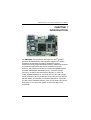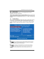
1
SBC84823 Series ® Intel Atom™ All-In-One Capa Board with LVDS User’s Manual Disclaimers This manual has been carefully checked and believed to contain accurate information. AXIOMTEK Co., Ltd. assumes no responsibility for any infringements of patents or any third party’s rights, and any liability arising from such use. AXIOMTEK does not warrant or assume any legal liability or responsibility for the accuracy, completeness or usefulness of any information in this document. AXIOMTEK does not make any commitment to update the information in this manual. AXIOMTEK reserves the right to change or revise this document and/or product at any time without notice. No part of this document may be reproduced, stored in a retrieval system, or transmitted, in any form or by any means, electronic, mechanical, photocopying, recording, or otherwise, without the prior written permission of AXIOMTEK Co., Ltd. Caution If you replace wrong batteries, it causes the danger of explosion. It is recommended by the manufacturer that you follow the manufacturer’s instructions to only replace the same or equivalent type of battery, and dispose of used ones. ©Copyright 2010 AXIOMTEK Co., Ltd. All Rights Reserved January 2010, Version A1 Printed in Taiwan ii ESD Precautions Computer boards have integrated circuits sensitive to static electricity. To prevent chipsets from electrostatic discharge damage, please take care of the following jobs with precautions: Do not remove boards or integrated circuits from their anti-static packaging until you are ready to install them. Before holding the board or integrated circuit, touch an unpainted portion of the system unit chassis for a few seconds. It discharges static electricity from your body. Wear a wrist-grounding strap, available from most electronic component stores, when handling boards and components. Trademarks Acknowledgments AXIOMTEK is a trademark of AXIOMTEK Co., Ltd. ® Windows is a trademark of Microsoft Corporation. Phoenix & AWARD are trademarks of Phoenix Technology Ltd. IBM, PC/AT, PS/2, VGA are trademarks of International Business Machines Corporation. ® ® Intel and Pentium are trademarks of Intel Corporation. Winbond is a trademark of Winbond Electronics Corp. Other brand names and trademarks are the properties and registered brands of their respective owners. iii Table of Contents Disclaimers ................................................................................. ii ESD Precautions........................................................................ iii CHAPTER 1 ............................................................................................... 1 INTRODUCTION ............................................................................... 1 1.1 Specifications............................................................ 2 1.2 Utilities Supported .................................................... 4 CHAPTER 2 ............................................................................................... 5 JUMPERS AND CONNECTORS...................................................... 5 2.1 Board Layout............................................................. 5 2.2 Board Dimensions and Fixing Holes ...................... 7 2.3 Jumper Settings........................................................ 9 2.3.1 Audio Output Jumper (JP1) ...................................... 10 2.3.2 LCD Voltage Selection Jumper (JP2)....................... 10 2.3.3 CompactFlash™ Power Selection Jumper (JP3) ..... 11 2.3.4 CMOS Clear Jumpers (JP4) ..................................... 11 2.3.5 AUTO POWER BUTTON Mode Jumper (JP5)......... 12 2.3.6 CPLD JTAG Programming Interface Connector (JP6)12 2.3.7 COM1~COM4 Mode Select for Type Jumpers: (JP9, JP10, JP7, JP8)..................................................................... 13 2.4 Connectors .............................................................. 14 2.4.1 VGA Connector (CN19) ............................................ 15 2.4.2 DC POWER JACK Connector (ATX1)...................... 16 2.4.3 LVDS Flat Panel Connector (CN2)........................... 16 2.4.4 Serial ATA Power Connector (CN7) ......................... 17 2.4.5 Flat Panel Bezel Connector (CN4) ........................... 17 2.4.6 Digital I/O Connector (CN6)...................................... 18 2.4.7 LVDS Backlight Connector (CN3) ............................ 18 2.4.8 SMBUS Connector (CN13)....................................... 19 2.4.9 Ethernet LAN Connector (CN14)............................. 19 2.4.10 Serial ATA Connector (CN8).................................... 20 2.4.11 DDRII SODIMM Connector (SCN1) ......................... 20 2.4.12 CompactFlash™ Socket (SCN2) ............................. 21 2.4.13 Serial Port1 Connector (CN17) ................................ 22 2.4.14 Serial Port 2 Connectors (CN12) ............................. 23 2.4.15 Serial Port 3, 4 Connectors (CN10) ......................... 23 2.4.16 USB Port Connector (CN15,CN16).......................... 24 iv 2.4.17 2.4.18 2.4.19 2.4.20 Internal USB Connector (CN11)............................... 24 PS/2 Keyboard and Mouse Connector (CN18)......... 25 Audio Phone Jack Connector (CN1)......................... 25 Mini PCI-Express Card Connector: (CN5,CN9) ........ 25 CHAPTER 3 ............................................................................................. 28 HARDWARE DESCRIPTION........................................................ 28 3.1 Microprocessors............................................................ 28 3.2 BIOS ................................................................................ 28 3.3 System Memory ............................................................. 28 3.4 I/O Port Address Map .................................................... 28 3.5 Interrupt Controller........................................................ 30 CHAPTER 4 ............................................................................................. 31 PHOENIX-AWARD BIOS UTILITY ...................................................... 31 4.1 Entering Setup ............................................................... 31 4.2 Control Keys .................................................................. 32 4.3 Getting Help ................................................................... 33 4.4 The Main Menu................................................................ 33 4.5 Standard CMOS Setup Menu......................................... 34 4.6 Advanced BIOS Features ............................................. 36 4.7 Advanced Chipset Features ......................................... 41 4.8 Integrated Peripherals .................................................. 43 4.9 Power Management Setup............................................. 48 4.10 PnP/PCI Configuration Setup....................................... 49 4.11 PC Health Status............................................................ 51 4.12 Load Optimized Defaults .............................................. 52 4.13 Set Supervisor/User Password.................................... 53 4.14 Save & Exit Setup .......................................................... 54 4.15 Exit Without Saving....................................................... 55 CHAPTER 5 ............................................................................................. 56 INSTALLATION OF DRIVERS ............................................................. 56 5.1 Installing Chipset Driver ................................................ 56 5.2 Installing VGA Driver ..................................................... 59 5.3 Installing LAN Driver ...................................................... 62 5.4 Installing Audio Driver ................................................... 64 APPENDIX A............................................................................................ 66 v WATCHDOG TIMER .............................................................................. 66 APPENDIX B............................................................................................ 68 DIGITAL I/O.............................................................................................. 68 vi SBC84823 Series All-In-One CAPA Board User’s Manual CHAPTER 1 INTRODUCTION ® The SBC84823 is a Capa board with support for Intel ATOM™ ® processor Z510PT/Z520PT, and integrates chipset Intel System Controller Hub US15WPT that deliver outstanding system performance through high-bandwidth interfaces, multiple I/O functions for interactive applications and various embedded computing solutions. The board has one 200-pin unbuffered SODIMM sockets for DDR2 400/533 MHz SO-DIMM memory, maximum memory capacity up to 2GB. It also features dual-display by VGA and LVDS, Gigabit/Fast Ethernet, one serial ATA port, six USB 2.0 high speed compliant, built-in high definition audio codec that can achieve the best stability and reliability for industrial applications. It provides you with unique embedded features, such as four serial ports (4x RS232) and 3.5’’ form factor that applies an extensive array of PC peripherals. Introduction 1 SBC84823 Series All-In-One CAPA Board User’s Manual 1.1 Specifications CPU z ® TM Intel ATOM processor Z510PT/Z520PT System Chipset z ® Intel System Controller Hub US15WPT BIOS z Phoenix-Award BIOS, Y2K compliant 8Mbit FWH Flash, DMI, Plug and Play SmartView for multiple LCD type selection, display mode option and application extension features “Load Optimized Default” to backup customized setting in the BIOS flash chip to prevent from CMOS battery fail z System Memory One x 200-pin unbuffered DDR2 SODIMM socket Maximum to 2GB DDR2 400/533 MHz memory z Onboard Multi I/O Controller: Winbond W83627DHG-P Serial Ports: four ports for RS-232 z CompactFlash™ Socket One CompactFlash™ Type II low profile slot z USB Interface Six USB ports with fuse protection and complies with USB Spec. Rev. 2.0 z Display One 2 x 20-pin LVDS connector, one 7-pin wafer connector for inverter control One D-sub 15-pin slim type connector z Watchdog Timer 1~255 seconds; up to 255 levels 2 Introduction SBC84823 Series All-In-One CAPA Board User’s Manual z Ethernet One port with Intel82574IT for Gigabit/Fast Ethernet One RJ-45 connector z Audio HD Audio compliant (with Speaker/line-out & MIC-in) via ALC888 Supports multi-channel audio stream, 32-bit sample depth, and sample rate up to 192KHz Line-in/Line-out/MIC-in z Power Management ACPI (Advanced Configuration and Power Interface) z Form Factor 3.5’’ form factor NOTE All specifications and images are subject to change without notice. Introduction 3 SBC84823 Series All-In-One CAPA Board User’s Manual 1.2 Utilities Supported Chipset Driver Ethernet Driver Graphic Drivers Audio Drivers z z z z 4 Introduction SBC84823 Series All-In-One CAPA Board User’s Manual CHAPTER 2 JUMPERS AND CONNECTORS 2.1 Board Layout Component Side Jumpers and Connectors 5 SBC84823 Series All-In-One CAPA Board User’s Manual Solder Side 6 Jumpers and Connectors SBC84823 Series All-In-One CAPA Board User’s Manual 2.2 Board Dimensions and Fixing Holes Component Side Jumpers and Connectors 7 SBC84823 Series All-In-One CAPA Board User’s Manual Solder Side 8 Jumpers and Connectors SBC84823 Series All-In-One CAPA Board User’s Manual 2.3 Jumper Settings Proper jumper settings configure the SBC84823 to meet your application purpose. We are herewith listing a summary table of all jumpers and default settings for onboard devices, respectively. Jumper Default Setting Jumper Setting JP1 Audio Speak Out/Line Out Selection Default: Line Out Short 1-3, 2-4 JP2 LVDS Voltage Selection Default: 3.3V Short 1-2 JP3 Compact Flash Voltage Selection Default: 3.3V Short 1-2 JP4 Normal Operation/Clear CMOS setting Default: Normal Operation Auto Power Button Mode Selection Default: Disable Short 1-2 JP6 CPLD programming interface N/A JP7 COM3 Mode Select JP5 Short 1-2 CN10 Pin 1: DCD Short 3-5 CN10 Pin 9: RI Short 4-6 JP8 COM4 Mode Select CN10 Pin 1: DCD Short 3-5 JP9 COM1 Mode Select CN10 Pin 9: RI Short 4-6 CN17 Pin 1: DCD Short 3-5 CN17 Pin 9: RI JP10 COM2 Mode Select CN12 Pin 1: DCD Short 3-5 CN12 Pin 9: RI Jumpers and Connectors Short 4-6 Short 4-6 9 SBC84823 Series All-In-One CAPA Board User’s Manual 2.3.1 Audio Output Jumper (JP1) This jumper is to select the Audio output. Description Function Jumper Setting Audio Output Line Out (Default) Speaker Out 2.3.2 LCD Voltage Selection Jumper (JP2) The board supports +3.3V or +5V flat panel displays. Configure the jumper JP2 to the appropriate voltage of the flat panel. Description Function Jumper Setting LCD Voltage 3.3V Selection (Default) 5V 10 Jumpers and Connectors SBC84823 Series All-In-One CAPA Board User’s Manual 2.3.3 CompactFlash™ Power Selection Jumper (JP3) This jumper is to select the voltage for CompactFlash™ interface. Description CompactFlash™ Power Select Function Jumper Setting 3.3V (Default) 5V 2.3.4 CMOS Clear Jumpers (JP4) You may need to use this jumper is to clear the CMOS memory if incorrect settings in the Setup Utility. Description CMOS Clear Function Jumper Setting Normal (Default) Clear CMOS Jumpers and Connectors 11 SBC84823 Series All-In-One CAPA Board User’s Manual 2.3.5 AUTO POWER BUTTON Mode Jumper (JP5) The jumper selects the AUTO Power BUTTON Mode. Description Function Jumper Setting AUTO Power Disable BUTTON Mode (Default ATX Selection mode) Enable (AT mode) 2.3.6 CPLD JTAG Programming Interface Connector (JP6) The jumper is a 2.0mm Pin header connector for CPLD Interface Connector. Pin 12 Signal 1 +3.3V SBY 2 GND 3 TCK 4 TDO 5 TDI Jumpers and Connectors SBC84823 Series All-In-One CAPA Board User’s Manual 2.3.7 COM1~COM4 Mode Select for Type Jumpers: (JP9, JP10, JP7, JP8) COM1 (CN17) Pin 1=5V *Pin 1=DCD Pin 9=12V *Pin 9=RI COM3 (CN10) Pin 1=5V *Pin 1=DCD Pin 9=12V *Pin 9=RI JP9 Short 1-3 Short 3-5 Short 2-4 Short 4-6 JP7 Short 1-3 Short 3-5 Short 2-4 Short 4-6 COM2 (CN12) Pin 1=5V *Pin 1=DCD Pin 9=12V *Pin 9=RI COM4 (CN10) Pin 1=5V *Pin 1=DCD Pin 9=12V *Pin 9=RI JP10 Short 1-3 Short 3-5 Short 2-4 Short 4-6 JP8 Short 1-3 Short 3-5 Short 2-4 Short 4-6 JP7, JP8, JP9, JP10 Jumpers and Connectors 13 SBC84823 Series All-In-One CAPA Board User’s Manual 2.4 Connectors Connectors connect the board with other parts of the system. Loose or improper connection might cause problems. Make sure all connectors are properly and firmly connected. Here is a summary table shows you all connectors on the SBC84823 Series. Connectors +8V~+24V Power Connector ATX1 DDRII RAM Connector SCN1 CF Card Connector SCN2 Audio Connector CN1 LVDS Connector CN2 LVDS Backlight Connector CN3 Flat Panel Bezel Connector CN4 Mini card connector CN5, CN9 Digital I/O (DIO) Connector CN6 SATA power connector CN7 SATA Connector 14 Label CN8 COM3,4 Connector CN10 USB*2 Connector CN11 COM2 Connector CN12 SMBUS Connector CN13 LAN Connector CN14 USB*2 Stack Connector CN15 USB*2 Stack Connector CN16 COM1 Connector CN17 PS/2 KB/MS Connector CN18 VGA Connector CN19 Jumpers and Connectors SBC84823 Series All-In-One CAPA Board User’s Manual 2.4.1 VGA Connector (CN19) CN19 is a standard 15-pin DB15 connector commonly for the CRT VGA display. Pin Signal 1 Red 2 Green 3 Blue 4 N.C 5 Ground (GND) 6 AnalogGround(AGND) 7 AnalogGround(AGND) 8 AnalogGround(AGND) 9 N.C 10 Ground (GND) 11 N.C 12 DDC DATA 13 Horizontal Sync 14 Vertical Sync 15 DDC CLK Jumpers and Connectors 15 SBC84823 Series All-In-One CAPA Board User’s Manual 2.4.2 DC POWER JACK Connector (ATX1) +8V~+24V DC input to this connector. Pin 2 Signal 1 1 GND Connector (CN2) 2.4.3 LVDS Flat Panel CN2 40-pin 2 GND 3 +12V 4 +12V is a 4 3 connector. It is strongly recommended to use the matching JST SHDR40V-S-B connector. Pin Signal Pin Signal 1 VCCM 2 VCCM 3 VCCM 4 VCCM 5 VCCM 6 VCCM 7 N.C. 8 N.C. 9 GND 10 GND 11 N.C. 12 N.C. 13 N.C. 14 N.C. 15 GND 17 N.C. 16 18 GND N.C. 19 N.C. 20 N.C. 21 GND 22 GND 23 Channel A D0- 24 N.C. 25 Channel A D0+ 26 N.C. 27 GND 28 GND 29 Channel A D1- 30 Channel A D3- 31 Channel A D1+ 32 Channel A D3+ 33 GND 34 GND 35 Channel A D2- 36 Channel A CLK- 37 Channel A D2+ 38 Channel A CLK+ 39 GND 40 GND 16 Jumpers and Connectors SBC84823 Series All-In-One CAPA Board User’s Manual 2.4.4 Serial ATA Power Connector (CN7) CN7 is a 2.5mm wafer connector for Serial ATA Power. Pin Signal 1 +5V 2 GND 2.4.5 Flat Panel Bezel Connector (CN4) Power LED Pin 1 and Pin 5 connect the system power LED indicator with the corresponding switch on the case. Pin 1 is assigned as +, and Pin 3 & Pin 5 as -. The Power LED lights up when the system is powered ON. External Speaker and Internal Buzzer Connector Pin 2, 4, 6 and 8 can be connected to the case-mounted speaker unit or internal buzzer. While connecting the CPU card to an internal buzzer, please short pins 2-4; while connecting to an external speaker, you need to set pins 2-4 to Open and connect the speaker cable to pin 8 (+) and pin 2 (-). ATX Power On/Off Button Pin 9 and 10 connect the front panel’s ATX power button to the CPU card, which allows users to control ATX power supply to be power on/off. System Reset Switch Pin 11 and 12 connect to the case-mounted reset switch that reboots your computer without turning OFF the power switch. It is a better way to reboot your system for a longer life of the system’s power supply. Jumpers and Connectors 17 SBC84823 Series All-In-One CAPA Board User’s Manual HDD Activity LED This connection is linked to hard drive activity LED on the control panel. LED flashes when HDD is being accessed. Pin 13 and 14 connect the hard disk drive to the front panel HDD LED, Pin 13 assigned as -, and Pin 14 as +. 2.4.6 Digital I/O Connector (CN6) CN6 is an 8-channel digital I/O connector that meets requirements for a system customary automation control. The digital I/O can be configured to control cash drawers, sense warning signals from an Uninterrupted Power System (UPS), or perform store security control. The DIO Pin Signal Pin Signal 1 Digital Input 1 2 Digital Output 1 3 Digital Input 2 4 Digital Output 2 5 Digital Input 3 6 Digital Output 3 7 GND 8 Digital Output 4 9 GND 10 Digital Output 5 2.4.7 LVDS Backlight Connector (CN3) CN3 is DF13-7S-1.25C 7-pin connectors for inverter. We strongly recommend you to use the matching DF13-7S-1.25C connector. Pin 18 Signal 1 +12V 2 +12V 3 +5V 4 ENABLE +5V 5 GND 6 GND 7 GND Jumpers and Connectors SBC84823 Series All-In-One CAPA Board User’s Manual 2.4.8 SMBUS Connector (CN13) CN13 is for SMBUS interface support. Pin 2.4.9 Signal 1 CLOCK 2 DATA 3 GND Ethernet LAN Connector (CN14) CN14 is the RJ-45 connector is for Ethernet. Just plug in one end of the cable and connect the other end (phone jack) to a 1000/100/10-Base-T hub. Pin Signal 1 MDI0+ 2 MDI0- 3 MDI1+ 4 MDI1- 5 MDI2+ 6 MDI2- 7 MDI3+ 8 MDI3- A Active LED (Yellow) B 100 LAN LED (Green)/ 1000 LAN LED (Orange) Jumpers and Connectors 19 SBC84823 Series All-In-One CAPA Board User’s Manual 2.4.10 Serial ATA Connector (CN8) CN8 is for high-speed SATA interface port and can be connected to hard disk devices. Pin Signal 1 GND 2 SATA_TX+ 3 SATA_TX- 4 GND 5 SATA_RX- 6 SATA_RX+ 7 GND 2.4.11 DDRII SODIMM Connector (SCN1) 20 Jumpers and Connectors SBC84823 Series All-In-One CAPA Board User’s Manual 2.4.12 CompactFlash™ Socket (SCN2) The board is equipped with a CompactFlashTM disk type-II socket on the solder side that supports the IDE interface CompactFlashTM disk card with DMA mode supported. The socket is especially designed to avoid any incorrect installation of the CompactFlashTM disk card. TM When installing or removing the CompactFlash disk card, please TM make sure that the system power is off. The CompactFlash disk card is defaulted as the C: or D: disk drive in your PC system. Pin Signal Pin Signal 1 GND 26 CD1- 2 Data 3 27 Data 11 3 Data 4 28 Data 12 4 Data 5 29 Data 13 5 Data 6 30 Data 14 6 Data 7 31 Data 15 7 CS0# 32 CS1# 8 Address 10 33 VS1# 9 ATASEL 34 IORD# 10 Address 9 35 IOWR# 11 Address 8 36 WE# 12 Address 7 37 INTR 13 VCC 38 VCC 14 Address 6 39 CSEL# 15 Address 5 40 VS2# 16 Address 4 41 RESET# 17 Address 3 42 IORDY# 18 Address 2 43 DMAREQ 19 Address 1 44 DMAACK- 20 Address 0 45 DASP# 21 Data 0 46 PDIAG# Pin Signal Jumpers and Connectors Pin Signal 21 SBC84823 Series All-In-One CAPA Board User’s Manual 22 Data 1 47 Data 8 23 Data 2 48 Data 9 24 IOCS16# 49 Data 10 25 CD2# 50 GND 2.4.13 Serial Port1 Connector (CN17) CN17 is a standard DB-9 connector for COM1. Pin 22 Signal 1 DCD, Data carrier detect 2 RXD, Receive data 3 TXD, Transmit data 4 DTR, Data terminal ready 5 GND, ground 6 DSR, Data set ready 7 RTS, Request to send 8 CTS, Clear to send 9 RI, Ring indicator Jumpers and Connectors SBC84823 Series All-In-One CAPA Board User’s Manual 2.4.14 Serial Port 2 Connectors (CN12) The RS-232 pin assignment is listed on the following table for COM2. Pin Signal Pin Signal 1 Data Carrier Detect (DCD) 2 Data Set Ready (DSR) 3 Receive Data (RXD) 4 Request to Send (RTS) 5 Transmit Data (TXD) 6 Clear to Send (CTS) 7 Data Terminal Ready (DTR) 8 Ring Indicator (RI) 9 Ground (GND) 10 NC 2.4.15 Serial Port 3, 4 Connectors (CN10) Here is the pin assignment list for your reference. Pin Signal Pin 11 Signal 1 NDCD3 NDCD4 2 NDSR3 12 NDSR4 3 NRX3 13 NRX4 4 NRTS3 14 NRTS4 5 NTX3 15 NTX4 6 NCTS3 16 NCTS4 7 NDTR3 17 NDTR4 8 NRI3 18 NRI4 9 GND 19 GND 10 N.C 20 N.C Jumpers and Connectors 2 20 1 19 23 SBC84823 Series All-In-One CAPA Board User’s Manual 2.4.16 USB Port Connector (CN15,CN16) CN15 Pin Signal Pin Signal 1 USB VCC0 (5VSBY) 5 USB VCC0 (5VSBY) 2 USB D0- 6 USB D1- 3 USB D0+ 7 USB D1+ 4 Ground (GND) 8 Ground (GND) CN16 Pin Signal Pin Signal 1 USB VCC0 (5VSBY) 5 USB VCC0 (5VSBY) 2 USB D2- 6 USB D3- 3 USB D2+ 7 USB D3+ 4 Ground (GND) 8 Ground (GND) 2.4.17 Internal USB Connector (CN11) These Universal Serial Bus (USB) connectors on this board are for installing versatile USB interface peripherals. This is a 10pin standard USB connector . NOTE USB D6 supports USB2.0 only. Pin 1 Signal Pin Signal 3 USB VCC1 (5VSBY) USB D4- 4 USB VCC1 (5VSBY) USB D6- 5 USB D4+ 6 USB D6+ 7 Ground (GND) 8 Ground (GND) 9 Ground (GND) 10 Ground (GND) 24 2 Jumpers and Connectors SBC84823 Series All-In-One CAPA Board User’s Manual 2.4.18 PS/2 Keyboard and Mouse Connector (CN18) The board supports a keyboard and Mouse interface. CN18 is a DIN connector for PS/2 keyboard connection via “Y” Cable. Pin Signal 1 Keyboard Data 2 Mouse Data 3 GND 4 VCC 5 Keyboard Clock 6 Mouse Clock 2.4.19 Audio Phone Jack Connector (CN1) Pin Signal Pin Signal 1 MIC_IN 2 Ground (GND) 3 LINE_IN_L 4 Ground (GND) 5 LINE_IN_R 6 Ground (GND) 7 AUDIO_OUT_L 8 Ground (GND) 9 AUDIO_OUT_R 10 Ground (GND) 2.4.20 Mini PCI-Express Card Connector: (CN5,CN9) CN5,CN9 is a PCI Express Mini Card connector with support of USB interface only. A PCI Express Mini Card can be applied to USB 1.1 and 2.0. NOTE The Mini Card PCI-Express interface can be supported if we remove SATA function by BOM options. Jumpers and Connectors 25 SBC84823 Series All-In-One CAPA Board User’s Manual Pin 26 Signal Pin Signal 1 WAKE# 2 +3.3V 3 N.C 4 GND 5 N.C 6 +1.5V 7 GND 8 N.C 9 GND 10 N.C 11 CLK- 12 N.C 13 CLK+ 14 N.C 15 GND 16 N.C 17 N.C 18 GND 19 N.C 20 N.C 21 GND 22 PERST# 23 PERN1 24 +3.3VSB 25 PERP1 26 GND 27 GND 28 +1.5V 29 GND 30 SMB_CLK 31 PETN1 32 SMB_DATA 33 PETP1 34 GND 35 GND 36 USB_D- 37 N.C 38 USB_D+ Jumpers and Connectors SBC84823 Series All-In-One CAPA Board User’s Manual 39 N.C 40 GND 41 N.C 42 N.C 43 N.C 44 N.C 45 N.C 46 N.C 47 N.C 48 +1.5V 49 N.C 50 GND 51 N.C 52 +3.3V Jumpers and Connectors 27 SBC84823 Series All-In-One CAPA Board User’s Manual CHAPTER 3 HARDWARE DESCRIPTION 3.1 Microprocessors ® The SBC84823 Series supports Intel ATOM™ processor Z510PT/Z520PT which make your system operated under Windows 2000/XP, and Linux environment. The system performance depends on the microprocessor. Make sure all correct settings are arranged for your installed microprocessor to prevent the CPU from damages. 3.2 BIOS The SBC84823 Series uses Award Plug and Play BIOS with a single 8Mbit FWH Flash, DMI, Plug and Play. 3.3 System Memory The SBC84823 Series industrial CPU card supports one 200-pin unbuffered DDR2 SODIMM socket for a maximum memory of 2GB DDR2 SDRAMs. The memory module can come in sizes of 64MB, 128MB, 256MB, 512MB, 1GB and 2GB. The Device density supports 512Mb and 1024Mb with the width of x16. 3.4 I/O Port Address Map ® The Intel ATOM™ processor Z510PT/Z520PT can communicate via I/O ports. There are total 1KB port addresses available for assignment to other devices via I/O expansion cards. Address Devices 000-01F DMA controller #1 020-02D 024-025 028-029 02C-02D 02E-02F 030-031 034-035 038-039 03C-03D 040-043 050-053 04E-04F 060-06F Interrupt controller #1 Forwarded to LPC(LPC Super I/O 2) Interrupt controller #2 Timer/Counter (8254) 070-077 Forwarded to LPC(LPC Super I/O 1) Forwarded to LPC(Microcontroller for Keyboard Controller) Real time clock, NMI 080-091 DMA page register 28 Hardware Descriptionn SBC84823 All-Iin-one PICO ITX CPU Board 092 Processor I/F(Reset Generator) 093-09F DMA page register 0A0-0BF Interrupt controller #2 0C0-0DF DMA controller #2 0F0 Processor I/F 0F8-0FF Math processor 170-177 Forward to SATA(SATA Controller) 1F0-1F7 Forward to SATA(SATA Controller) 250-25F HR I/O 300-31F Prototype card 376 Forward to SATA(SATA Controller) 378-37F Parallel Port (LPT) 380-38F SDLC #2 3A0-3AF SDLC #1 Hardware Description 29 SBC84823 Series All-In-One CAPA Board User’s Manual Address Devices 3B0-3BF MDA video card 3C0-3CF EGA card 3D0-3DF CGA card 3F6 Forward to SATA (SATA Controller) 3F8-3FF Serial port #1 (COM1) 3E8-3EF Serial port #3 (COM3) 2F8-2FF Serial port #2 (COM2) 2E8-2EF Serial port #4 (COM4) 3.5 Interrupt Controller The SBC84823 Series is a 100% PC compatible control board. It consists of 16 interrupt request lines, and four out of them can be programmable. The mapping list of the 16 interrupt request lines is shown as the following table. IRQ Parity check error IRQ0 System timer output IRQ1 Keyboard IRQ2 Interrupt rerouting from IRQ8 through IRQ15 IRQ3 Serial port #2 IRQ4 Serial port #1 IRQ5 PCI Device Share IRQ7 — IRQ8 Real time clock IRQ9 ACPI Controller IRQ10 — IRQ11 — IRQ12 PS/2 Mouse IRQ13 Math coprocessor IRQ14 Primary IDE channel IRQ15 — 30 Hardware Descriptionn SBC84823 All-Iin-one PICO ITX CPU Board CHAPTER 4 PHOENIX-AWARD BIOS UTILITY The Phoenix-Award BIOS provides users with a built-in Setup program to modify basic system configuration. All configured parameters are stored in a battery-backed-up RAM (CMOS RAM) to save the Setup information whenever the power is turned off. 4.1 Entering Setup There are two ways to enter the Setup program. You may either turn ON the computer and press <Del> immediately, or press the <Del> and/or <Ctrl>, <Alt>, and <Esc> keys simultaneously when the following message appears at the bottom of the screen during POST (Power on Self Test). TO ENTER SETUP PRESS DEL KEY If the message disappears before you respond and you still want to enter Setup, please restart the system to try it again. Turning the system power OFF and ON, pressing the “RESET” button on the system case or simultaneously pressing <Ctrl>, <Alt>, and <Del> keys can restart the system. If you do not press keys at the right time and the system doesn’t boot, an error message will pop out to prompt you the following information: PRESS <F1> TO CONTINUE, <CTRL-ALT-ESC> OR <DEL> TO ENTER SETUP Phoenix Award BIOS Utility 31 SBC84823 Series All-In-One CAPA Board User’s Manual 4.2 Control Keys Up arrow Move to the previous item Down arrow Move to the next item Left arrow Move to the left side Right arrow Move to the right side Esc key Main Menu -- Quit and delete changes into CMOS Status Page Setup Menu and Option Page Setup Menu -- Exit current page and return to Main Menu PgUp/“+” key Increase the numeric value or make changes PgDn/“−“ key Decrease the numeric value or make changes F1 key General help, only for Status Page Setup Menu and Option Page Setup Menu 32 (Shift) F2 key Change color from total 16 colors. F2 to select color forward, (Shift) F2 to select color backward F3 key Reserved F4 key Reserved F5 key Restore the previous CMOS value from CMOS, only for Option Page Setup Menu F6 key Load the default CMOS value from BIOS default table, only for Option Page Setup Menu F7 key Load the Setup default, only for Option Page Setup Menu F8 key Reserved F9 key Reserved F10 key Save all the CMOS changes, only for Main Menu Phoenix Award BIOD Utility SBC84823 All-Iin-one PICO ITX CPU Board 4.3 Getting Help Main Menu The online description of the highlighted setup function is displayed at the bottom of the screen. Status Page Setup Menu/Option Page Setup Menu Press <F1> to pop out a small Help window that provides the description of using appropriate keys and possible selections for highlighted items. Press <F1> or <Esc> to exit the Help Window. 4.4 The Main Menu Once you enter the Award BIOS CMOS Setup Utility, the Main Menu appears on the screen. In the Main Menu, there are several Setup functions and a couple of Exit options for your selection. Use arrow keys to select the Setup Page you intend to configure then press <Enter> to accept or enter its submenu. NOTE If your computer can not boot after making and saving system changes with Setup, the Award BIOS will reset your system to the CMOS default settings via its built-in override feature. NOTE It is strongly recommended that you should avoid changing the chipset’s defaults. Both Award and your system manufacturer have carefully set up these defaults that provide the best performance and reliability. Phoenix Award BIOS Utility 33 SBC84823 Series All-In-One CAPA Board User’s Manual 4.5 Standard CMOS Setup Menu The Standard CMOS Setup Menu displays basic information about your system. Use arrow keys to highlight each item, and use <PgUp> <PgDn> key to select the value you want in each item. z Date The date format is <day>, <date> <month> <year>. Press <F3> to show the calendar. z Time This item shows current time of your system with the format <hour> <minute> <second>. The time is calculated based on the 24-hour militarytime clock. For example, 1 p.m. is 13:00:00. z IDE Primary Master/Primary Slave These items identify the types of each IDE channel installed in the computer. There are 45 predefined types (Type 1 to Type 45) and 2 user’s definable types (Type User) for Enhanced IDE BIOS. Press <PgUp>/<+> or <PgDn>/<−> to select a numbered hard disk type, or directly type the number and press <Enter>. Please be noted your drive’s specifications must match the drive table. The hard disk will not work properly if you enter 34 Phoenix Award BIOD Utility SBC84823 All-Iin-one PICO ITX CPU Board improper information. If your hard disk drive type does not match or is not listed, you can use Type User to manually define your own drive type. If selecting Type User, you will be asked to enter related information in the following items. Directly key in the information and press <Enter>. This information should be provided in the documentation from your hard disk vendor or the system manufacturer. If the HDD interface controller supports ESDI, select “Type 1”. If the HDD interface controller supports SCSI, select “None”. If the HDD interface controller supports CD-ROM, select “None”. CYLS. number of cylinders LANDZONE HEADS number of heads SECTORS PRECOMP write precom MODE landing zone number of sectors HDD access mode If there is no hard disk drive installed, select NONE and press <Enter>. z Video Select the display adapter type for your system. z Halt On This item determines whether the system will halt or not, if an error is detected while powering up. No errors The system booting will halt on any errors detected. (default) All errors Whenever BIOS detects a non-fatal error, the system will stop and you will be prompted. All, But Keyboard The system booting will not stop for a keyboard error; it will stop for other errors. Press <Esc> to return to the Main Menu page. Phoenix Award BIOS Utility 35 SBC84823 Series All-In-One CAPA Board User’s Manual 4.6 Advanced BIOS Features This section allows you to configure and improve your system, to set up some system features according to your preference. 36 Phoenix Award BIOD Utility SBC84823 All-Iin-one PICO ITX CPU Board z CPU Features Scroll to this item and press <Enter> to view the CPU Feature sub menu. Phoenix Award BIOS Utility 37 SBC84823 Series All-In-One CAPA Board User’s Manual z Harddisk boot priority Scroll to this item and press <Enter> to view the sub menu to decide the disk boot priority 38 Phoenix Award BIOD Utility SBC84823 All-Iin-one PICO ITX CPU Board System Setup System requires correct password before booting, and also before permitting access to the Setup page. System will boot, but requires correct password before permitting access to Setup. (Default value) NOTE To disable the security, select PASSWORD SETTING at Main Menu and then you will be asked to enter a password. Do not type anything, just press <Enter> and it will disable the security. Once the security is disabled, the system will boot and you can enter Setup freely. Phoenix Award BIOS Utility 39 SBC84823 Series All-In-One CAPA Board User’s Manual z APIC Mode APIC (Advanced Programmable Interrupt Controller) mode is enabled that provides symmetric multiprocessing (SMP) for systems. z MPS Version Control For OS This item specifies the version of the Multiprocessor Specification (MPS). Version 1.4 has extended configuration tables to improve support for multiple PCI bus configurations and provide future expandability. Press <Esc> to return to the Main Menu page. 40 Phoenix Award BIOD Utility SBC84823 All-Iin-one PICO ITX CPU Board 4.7 Advanced Chipset Features This section contains completely optimized chipset’s features on the board that you are strongly recommended to leave all items on this page at their default values unless you are very familiar with the technical specifications of your system hardware. Phoenix Award BIOS Utility 41 SBC84823 Series All-In-One CAPA Board User’s Manual z DRAM Timing Selectable Use this item to increase the timing of the memory. This is related to the cooling of memory. z System BIOS Cacheable Selecting Enabled allows caching of the system BIOS ROM at F0000hFFFFFh, resulting in better system performance. However, if any program writes to this memory area, a system error may result. The default value is “Disabled”. z Video BIOS Cacheable This item allows you to change the Video BIOS location from ROM to RAM. Video Shadow will increase the video speed. *** VGA Setting *** z On-Chip Frame Buffer Size Use this item to set the VGA frame buffer size. z Boot Type This item is to select Display Device that the screen will be shown. z LCD Panel Type This item is to allow you to adjust the panel resolution. z Panel Scaling This item shows the setting of panel scaling and operates the scaling function that the panel output can fit the screen resolution connected to the output port. Press <Esc> to return to the Main Menu page. 42 Phoenix Award BIOD Utility SBC84823 All-Iin-one PICO ITX CPU Board 4.8 Integrated Peripherals This section allows you to configure your OnChip IDE Device, Onboard Device, SuperIO Device and USB Device Setting. Phoenix Award BIOS Utility 43 SBC84823 Series All-In-One CAPA Board User’s Manual z OnChip IDE Device Scroll to this item and press <Enter> to view the sub menu OnChip IDE Device. ¾ IDE HDD Block Mode Block mode is also called block transfer, multiple commands, ormultiple sectors read/write. If your IDE hard drive supports block mode (most new drives do), select Enabled for automatic detection of the optimal number of block read/writes per sector the drive can support. Press <Esc> to return to the Integrated Peripherals page. 44 Phoenix Award BIOD Utility SBC84823 All-Iin-one PICO ITX CPU Board z Onboard Device Scroll to this item and press <Enter> to view the sub menu Onboard Device. ¾ Intel HD Audio Controller Choose Auto to enable an Intel HD Audio controller. Press <Esc> to return to the Integrated Peripherals page. Phoenix Award BIOS Utility 45 SBC84823 Series All-In-One CAPA Board User’s Manual z Super IO Device ¾ Onboard Serial Port 1/2/3/4 Select an address and corresponding interrupt for the serial port. There are several options for your selection. Press <Esc> to return to the Integrated Peripherals page. 46 Phoenix Award BIOD Utility SBC84823 All-Iin-one PICO ITX CPU Board z USB Device Setting Scroll to this item and press <Enter> to view the sub menu USB Device Setting. Press <Esc> to return to the Integrated Peripherals page. z Onboard Lan Boot ROM Use this item to enable or disable the Boot ROM function of the onboard LAN chip when the system boots up. Phoenix Award BIOS Utility 47 SBC84823 Series All-In-One CAPA Board User’s Manual 4.9 Power Management Setup The Power Management Setup allows you to save energy of your system effectively. It will shut down the hard disk and turn OFF video display after a period of inactivity. z ACPI Function Advanced Configuration and Power Management (ACPI). The function is always “Enabled”. 48 Phoenix Award BIOD Utility SBC84823 All-Iin-one PICO ITX CPU Board 4.10 PnP/PCI Configuration Setup This section describes the configuration of PCI (Personal Computer Interconnect) bus system, which allows I/O devices to operate at speeds close to the CPU speed while communicating with other important components. This section covers very technical items that only experienced users could change default settings. z Reset Configuration Data Normally, you leave this item Disabled. Select Enabled to reset Extended System Configuration Data (ESCD) when you exit Setup or if installing a new add-on cause the system reconfiguration a serious conflict that the operating system can not boot. Options: Enabled, Disabled. z Resources Controlled By The Award Plug and Play BIOS can automatically configure all boot and Plug and Play-compatible devices. If you select Auto, all interrupt request (IRQ), DMA assignment and Used DMA fields disappear as the BIOS automatically assign them. The default value is “Auto”. The other option is “Manual” Phoenix Award BIOS Utility 49 SBC84823 Series All-In-One CAPA Board User’s Manual z IRQ Resources When resources are controlled manually, assign each system interrupt to one of the following types in accordance with the type of devices using the interrupt: 1. Legacy ISA Devices compliant with the original PC AT bus specification, requiring a specific interrupt (such as IRQ4 for serial port 1). 2 . PCI/ISA PnP Devices compliant with the Plug and Play standard, whether designed for PCI or ISA bus architecture.The default value is “PCI/ISA PnP”. z PCI/VGA Palette Snoop Some non-standard VGA display cards may not show colors properly. This item allows you to set whether MPEG ISA/VESA VGA Cards can work with PCI/VGA or not. When enabled, a PCI/VGA can work with a MPEG ISA/VESA VGA card; when disabled, a PCI/VGA cannot work with a MPEG ISA/VESA Card. ** PCI Express relative items ** z Maximum Payload Size When using DDR SDRAM and Buffer size selection, another consideration in designing a payload memory is the size of the buffer for data storage. Maximum Payload Size defines the maximum TLP (Transaction Layer Packet) data payload size for the device. Press <Esc> to return to the Main Menu page. 50 Phoenix Award BIOD Utility SBC84823 All-Iin-one PICO ITX CPU Board 4.11 PC Health Status This section supports hardware monitoring that lets you monitor those parameters for critical voltages, temperatures and fan speed of the board. Press <Esc> to return to the Main Menu page. Phoenix Award BIOS Utility 51 SBC84823 Series All-In-One CAPA Board User’s Manual 4.12 Load Optimized Defaults This option allows you to load your system configuration with default values. These default settings are optimized to enable high performance features. To load CMOS SRAM with SETUP default values, please enter “Y”. If not, please enter “N”. 52 Phoenix Award BIOD Utility SBC84823 All-Iin-one PICO ITX CPU Board 4.13 Set Supervisor/User Password You can set a supervisor or user password, or both of them. The differences between them are: 1 Supervisor password: You can enter and change the options on the setup menu. 2 User password: You can just enter, but have no right to change the options on the setup menu. When you select this function, the following message will appear at the center of the screen to assist you in creating a password. ENTER PASSWORD Type a maximum eight-character password, and press <Enter>. This typed password will clear previously entered password from the CMOS memory. You will be asked to confirm this password. Type this password again and press <Enter>. You may also press <Esc> to abort this selection and not enter a password. To disable the password, just press <Enter> when you are prompted to enter a password. A message will confirm the password is getting disabled. Once the password is disabled, the system will boot and you can enter Setup freely. PASSWORD DISABLED When a password is enabled, you have to type it every time you enter the Setup. It prevents any unauthorized persons from changing your system configuration. Additionally, when a password is enabled, you can also require the BIOS to request a password every time the system reboots. This would prevent unauthorized use of your computer. You decide when the password is required for the BIOS Features Setup Menu and its Security option. If the Security option is set to “System”, the password is required during booting up and entry into the Setup; if it is set as “Setup”, a prompt will only appear before entering the Setup. Phoenix Award BIOS Utility 53 SBC84823 Series All-In-One CAPA Board User’s Manual 4.14 Save & Exit Setup This section allows you to determine whether or not to accept your modifications. Type “Y” to quit the setup utility and save all changes into the CMOS memory. Type “N” to bring you back to the Setup utility. 54 Phoenix Award BIOD Utility SBC84823 All-Iin-one PICO ITX CPU Board 4.15 Exit Without Saving Select this option to exit the Setup utility without saving changes you have made in this session. Type “Y”, and it will quit the Setup utility without saving your modifications. Type “N” to return to the Setup utility. Phoenix Award BIOS Utility 55 SBC84823 Series All-In-One CAPA Board User’s Manual CHAPTER 5 INSTALLATION OF DRIVERS The device drivers are located on the Product Information CD-ROM that comes with the SBC84823 Series package. The auto-run function of drivers will guide you to install the utilities and device drivers under a Windows system. You can follow the onscreen instructions to install these devices: „ Chipset „ VGA „ LAN „ Audio 5.1 Installing Chipset Driver 1 Run the® SETUP.EXE program from the driver directory in your 2 An Intel License Agreement appears to show you the important information. Click “Yes” to next step. 3 Please wait while running the following setup operations. 56 Installation of Driver SBC84823 All-Iin-one PICO ITX CPU Board (3-1) Installation of Drivers 57 SBC84823 Series All-In-One CAPA Board User’s Manual (3-2) 4. Click “Finish” to complete the setup process. 5. You will be asked to reboot your computer when the installation is completed. Please click “Yes, I want to restart my computer now” if you don’t need to install any other drivers. Otherwise, please click “No, I will restart my computer later”, and go on next step. 58 Installation of Driver SBC84823 All-Iin-one PICO ITX CPU Board 5.2 Installing VGA Driver 1 Run the SETUP.EXE program from the driver directory in your driver CD. Click “Next” to next step. ® 2 An Intel License Agreement appears to show you the important information. Click “Yes” to next step. 3 The message of Readme File Information appears to show you the system requirements and installation information. Please click “Next”. Installation of Drivers 59 SBC84823 Series All-In-One CAPA Board User’s Manual 4. Please wait while running the following setup operations. 4. When this message appears, please click “Next”. 5. You will be asked to reboot your computer when the installation is completed. Please click “Yes, I want to restart my computer now” if you don’t need to install any other drivers. Otherwise, please click “No, I will restart my computer later”, and click “Finish” to complete the installation. 60 Installation of Driver SBC84823 All-Iin-one PICO ITX CPU Board NOTE After installing VGA driver, if you restart, please press Hot Key “Ctrl+Alt+F1” to back VGA because the default display is LVDS LCD. Installation of Drivers 61 SBC84823 Series All-In-One CAPA Board User’s Manual 5.3 Installing LAN Driver Run the InstallShield Wizard for Ethernet from the driver Click “Install” to start the installation. 1. Please wait while running the following installation operation. 2. Click “Finish” to complete the installation. 62 Installation of Driver SBC84823 All-Iin-one PICO ITX CPU Board Installation of Drivers 63 SBC84823 Series All-In-One CAPA Board User’s Manual 5.4 Installing Audio Driver 1. Run the InstallShield Wizard for Audio from the driver directory in yourdriver 2. CD. Click “Next” to next step. Please wait while running the following installation operation. 64 Installation of Driver SBC84823 All-Iin-one PICO ITX CPU Board 3. You will be asked to reboot your computer when the installation is completed. Please click “Yes, I want to restart my computer now” if you don’t need to install any other drivers. Otherwise, please click “No, I will restart my computer later”, and click “Finish” to complete the installation. Installation of Drivers 65 SBC84823 Series All-In-One CAPA Board User’s Manual APPENDIX A WATCHDOG TIMER Watchdog Timer Setting (From Super I/O W83627DHG-P) After the system stops working for a while, it can be auto-reset by the Watchdog Timer. The integrated Watchdog Timer can be set up in the system reset mode by program. Using the Watchdog Function Start ↓ Un-Lock WDT: O 2E 87 ; Un-lock super I/O O 2E 87 ; Un-lock super I/O ↓ WDT Function: O 2E 2D ; O 2F 20 ; Mulit function pin select for WDT ↓ Select Logic device: O 2E 07 O 2F 08 ↓ Activate WDT: O 2E 30 O 2F 01 ↓ Set Second or Minute : O 2E F5 O 2F N N=00 or 08 (See below table) ↓ Set base timer : O 2E F6 O 2F M=00,01,02,…FF(Hex) ,Value=0 to 255 ↓ ; IF to disable WDT: O 2E 30 O 2F 00 ; Can be disable at any time 66 Watchdog Timer SBC84823 All-Iin-one PICO ITX CPU Board z Timeout Value Range 1 to 255 Minute / Second z Program Example Watchdog Timer can be set to system reset after 5-second timeout. O 2E 87 O 2E 87 O 2E 2D O 2F 20 O 2E 07 O 2F 08 Logical Device 8 O 2E 30 Activate O 2F 01 O 2E F5 O 2F N Set Minute or Second N=08 (Min),00(Sec) O 2E F6 O 2F M Watchdog Timer Set Value M = 00 ~ FF 67 SBC84823 Series All-In-One CAPA Board User’s Manual APPENDIX B DIGITAL I/O Digital I/O Software Programming Program deafault setting: 3IN/5OUT (W83627DHG) GPI GPO O 2E 87 O 2E 87 O 2E 07 O 2F 09 O 2E 30 O 2F 02 O 2E F9 O 2F 00 O 2E F0 O 2F 07 O 2E F1 I 2F Pin Signal O 2E 87 O 2E 87 O 2E 07 O 2F 09 O 2E 30 O 2F 02 O 2E F9 O 2F 00 O 2E F0 O 2F 07 O 2E F1 O 2F M (Note) Pin CN6 Signal 1 Digital Input 1 2 Digital Output 1 3 Digital Input 2 4 Digital Output 2 5 Digital Input 3 6 Digital Output 3 7 GND 8 Digital Output 4 9 GND 10 Digital Output 5 NOTE: M is Output Data Digital Output Bit7 DO4 68 Bit6 DO3 Bit5 DO2 Bit4 DO1 Digital Input Bit3 DO0 Bit2 DI2 Bit1 DI1 Bit0 DI0 Digital I/O