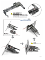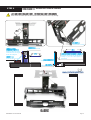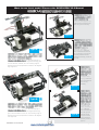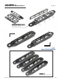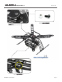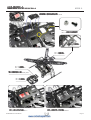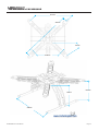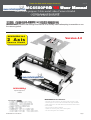
1
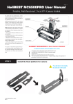
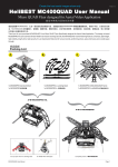
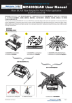
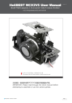
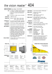
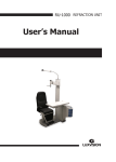
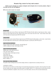
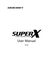
Create the best aerial images show only
Version 1.0
ual
Manual
HeliBEST MC6500PRO
MC6500PRO V4 User Man
Small Multi-purpose 2 Axis aerial video Camera Gimbal
IMPORTANT: Please read through this manual in its entirety before attempting to assemble or use
the camera gimbal.
MC6500PRO V4.0
2 Axis
Version 4.0
Camera Gimbal
DCS2600Digi
Especial Digital Servo
Included
MC6500PRO V4
MC6500PRO V2 new features:
- Strengthen the frame structure, the effective load increases to 800g.
- Perfect support for an invert mode and GOPRO HD upright installation.
- Wider camera mount, the SONY NEX5 and orther Mircro DSLR Camera
can be installed.
- Servo screws can easily be installed.
- Optimize the center of gravity of the camera gimbal.
- Arm and Landing Gear can be installed.
MC6500PRO V4.0 User Manual
Page 1
STEP 1
| Install the Dampers
1. Use moderate force, too tight may break the parts;
2. Pay attention to the installation direction of the damper as seen above;
3. Do not apply too much force when rotate or press the damper output shaft rough, it may break the parts
4. Do not drip the adhesive into the damper output shaft, it may break the parts
STEP 2
Install the rolling control arms
Prepare the parts above
1. Pay attention to the installation direction of the parts;
2. Apply the adhesive on the back of the joints could keep the appearance;
3. Do not apply the adhesive on the fingers, to avoid leaving the finger prints on the parts
4. Do not loose your hand until the adhesive dry, to make sure that all the parts are adhered perfectly
MC6500PRO V4.0 User Manual
Page 2
STEP 3
| Install the rolling actuating arm
Prepare the parts
Install the parts as seen on the left, using the instant
adhesive at all crossed position
STEP 4
Assembled
| Install the digital servo to camera gimbal
DCS2600Digi
High Speed Digital Servo
Prepare the parts above
MC6500PRO comes with 2 ultra-precision digital servos DCS2600Digi, which is specialized for camera mount
control. The control program applied in this servo is optimized for the control of the camera mount, so the servo runs
smoothly when working and reflects accurately at working. The moment of force of DSC2600Digi is 3.0kg/cm; the
speed could reach 0.06s/60. At the meantime, it uses quick reaction coreless motor.
This performance of this specialized camera mount digital servo is superior to any other common tail servo in the
market. The special design meets the requirements for the performance of the camera gimbal.
MC6500PRO V4.0 User Manual
Page 3
1. Before installation, please take the servo horns off (as seen on the right).
2. Fix the servo by 2 nylon screws.
3. Power on and confirm the angle, then install the servo horn of the servos.
4. Using 2 nylon screws to fix the servo. Install the servo as the picture above.
Prepare the parts above
Note arrange the servo wire
MC6500PRO V4.0 User Manual
Page 4
Assembled
STEP 5
| Install the camera mount
Example for install SONY NEX5
Prepare the parts above
For adjust the C.G of the camera when use some lens.
For the High C.G. of camera, such as: Panasonc GH2,Olympus E-M5 etc.
For the vast majority of camera, such as: GOPRO, SONY NEX5 etc.
MC6500PRO V4.0 User Manual
Page 5
STEP 6
Install the control linkers
Must confirm the neutral point of servo before install arms else the servo may damage.
Connect to the 1st. hole
Connect to the 2nd. hole
12345678901
12345678901
12345678901
When the rolling arm is at a
12345678901
12345678901
12345678901
horizontal level, the angle
12345678901
12345678901
12345678901
12345678901
should be 90 degrees.
12345678901
12345678901
12345678901
12345678901
12345678901
12345678901
12345678901
Connect to the 2nd. hole
12345678901
12345678901
12345678901
1234567890123
1234567890123
1234567890123 12345678901
12345678901
90 degree is recommanded
1234567890123
12345678901
1234567890123
1234567890123 12345678901
12345678901
1234567890123456789012345678901212345678901234567890123456789
1234567890123456789012345678901212345678901234567890123456789
12345678901
1234567890123456789012345678901212345678901234567890123456789
12345678901
1234567890123456789012345678901212345678901234567890123456789
1234567890123456789012345678901212345678901234567890123456789
1234567890123456789012345678901212345678901234567890123456789
1234567890123456789012345678901212345678901234567890123456789
1234567890123456789012345678901212345678901234567890123456789
1234567890123456789012345678901212345678901234567890123456789
1234567890123456789012345678901212345678901234567890123456789 Connect to the fifth hole
1234
1234
1234
1234
1234
1234
1234
1234
1234
1234
1234
1234
1234
1234
1234
1234
1234
1234
1234
The length of the linkage can be adjusted ac- 1234
1234
1234
1234
1234
1234
1234
cording
to
your
own
needs.(49mm
is
1234
1234
1234
1234
1234
1234
recommand)
1234
1234
1234
1234
1234
1234
1234
1234
1234
1234
1234
1234
1234
1234
1234567890123456789012345678901212345678901234567890123456789
1234567890123456789012345678901212345678901234567890123456789
1234567890123456789012345678901212345678901234567890123456789
1234567890123456789012345678901212345678901234567890123456789
1234567890123456789
1234567890123456789012345678901212345678901234567890123456789
1234567890123456789
1234567890123456789012345678901212345678901234567890123456789
1234567890123456789
1234567890123456789
1234567890123456789
1234567890123456789
Assembled
MC6500PRO V4.0 User Manual
Page 6
Three ways to connect MC6500PRO V4 to X650 Value
1
Optional parts:
Item number: L3010 x 2
Item Number: M3011 x 1
2
Optional parts:
Item number: L3004 x 4
Item number: L3003 x 4
Item Number: M3011 x 1
Put the damper pipe on
Put the O-ring
on the pipe
3
Damper pipe and O-ring come with MC6500PRO for free.
MC6500PRO V4.0 User Manual
Page 7
Want to use invert mode? Please refer MC6500PRO V2.0 Manual.
Vertical photography way:
make the lens of GOPRO HD
face the ground vertically.
Type-A1
Type-A
Type-A2
Inverted low angle
shooting way: make the
lens of GOPRO HD face the
sky vertically.In this way,the
camera gimbal should be
installed invertedly.( similar to
Type-B)
For the vast majority of
small-scale model aircrafts with heightened landing gear,
such as X650V4, X650V8, etc. The shooting angle is
between the former perspective to maximum 60 degrees
high angle shot.
Straight shooting way:make the
lens of GOPRO HD
face the sky
vertically.
Type-B1
Type-B
For the vast majority of
small-scale model aircrafts without heightened landing
gear, such as X450Pro, F450, etc. The shooting angle is
between the former perspective to maximum 60 degrees
low angle shot.
MC6500PRO V4.0 User Manual
Type-B2
Hoisting high
angle shooting
way: make the
lens of GOPRO HD
face the ground
vertically.In this
way,the camera
gimbal should be
hoisted.( similar to
Type-A)
Page 8
Extend your MC6500PRO
MC6500PRO
Use MC6500PRO-L(Optional parts) and MC6500PRO-A(Optional parts) let your
MC6500PRO become MC400QUAD Aerial Aircraft.
Packing List
A
B
1x MC6500PRO Camera Gimbal
1x MC6500PRO
C
1x MC6500PRO-L (Landing Gear)
1x MC6500PRO-L (
1x MC6500PRO-A (MC400QUAD Frame)
1x MC6500PRO-A (
A+B=MC6500PRO V3L
A+B+C=MC400QUAD
for any flyer which no landing Gear
MC6500PRO V4.0 User Manual
for 450EP R/C Helicopter
Complete picture of MC400QUAD
Page 9
Important:
1. MC400QUAD is combined with MC6500PRO(3.0 version min) , MC6500PRO-L and MC6500PRO-A.
2. MC400QUAD does not include other electronic devices but two servos. if you want to assemble a complete aircraft, you need to purchaseother
devices, such as:flight control, motor, ESC, radio, battery, charger, etc.
3. Please carefully read the assembly instructions for a smooth assembly.
Assemble the MC6500PRO-L
M3 x 30
M3 x 30 Nylon Pillar
M3 x 10
M3 x 10 Nylon Screw
for any flyer which no landing Gear
MC6500PRO V4.0 User Manual
for 450EP R/C Helicopter
Direct clamping installed
Page 10
Assemble the MC6500PRO-A
STEP 1
Before assembly, please adjust the direction of the Motor scrow holes.
Complete assembly of the four-arms
MC6500PRO V4.0 User Manual
Page 11
STEP 2
Assemble the MC6500PRO-A
M3 x 6
M3 x 6 Socket Screw and Nut
Attention to the position of screw holes
M3 x 10
M3 x 10 Nylon Screw and Nut
MC6500PRO V4.0 User Manual
Page 12
STEP 3
Assemble the MC6500PRO-A
Glue the Mounting Plate to the top of the Gimbal.
M2.5 x 6
M2.5 x 6 Socket Screw and Nut
M3 x 20
M3 x 20 Nylon Pillar
M3 x 10
M3 x 10 Nylon Screw
M3 x 10
M3 x 10 Nylon Screw
Assemble the Top Plate and Battery Plate.
M3 x 20
M3 x 20 Nylon Pillar
Example 1: Install the DJI NAZA F.C.
MC6500PRO V4.0 User Manual
Example 2: Install the DJI WK-M IMU Module
Page 13
Complate
Assemble the MC6500PRO-A
M3 x 6
M3 x 6 Socket Screw and Nut
The weight of MC400QUAD Parts
MC6500PRO-V3L
179g
MC6500PRO-L 63.5g
MC6500PRO V3 115g
MC400QUAD
346g
MC6500PRO-A 162g
MC6500PRO V4.0 User Manual
Page 14
The dimension of MC400QUAD
281mm
397mm
147mm
246mm
135mm
118mm
246mm
MC6500PRO V4.0 User Manual
Page 15
DEMO
Demonstration
Put the damper pipe on
Put the O-ring
on the pipe
Install the MC6500PRO V2 on XAircraft X650V4
Install the MC6500PRO on SIGMA Y6-500FG
Install the MC6500PRO on XAircraft DIY-HEXA
Install the MC6500PRO V2 on DJI F450
MC6500PRO V4.0 User Manual
Install the MC6500PRO V2 on SIGMA Y6-400W
Page 16
MC6500PRO
Camera Gimbal
Aerial Video
MC6500PRO V4.0 User Manual
Page 17