1
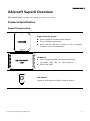
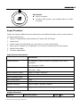
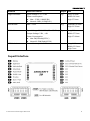
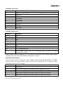
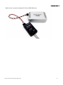
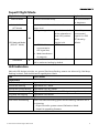
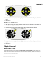
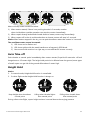
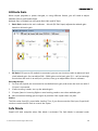
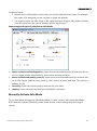
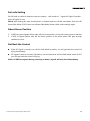
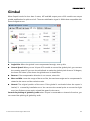
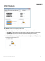
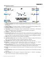
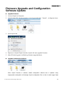
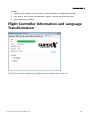
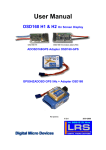
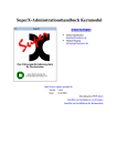
User Manual V1.8 目 录 XAircraft SuperX Overview ............................................................................................................ 2 Products Specification ............................................................................................................ 2 SuperX Construction ....................................................................................................... 2 SuperX Features ................................................................................................................ 3 SuperX Interface ....................................................................................................................... 4 SuperX Flight Mode ................................................................................................................. 7 LED Indication ............................................................................................................................ 7 SuperX Quick Guide ................................................................................................................ 8 Notes for Use ............................................................................................................................. 8 Installation ........................................................................................................................................... 9 Install SuperX Modules........................................................................................................... 9 Connection to Receiver ........................................................................................................ 10 HITEC,FUTABA, (WFLY)Wiring ............................................................................ 10 JR,Spektrum Wiring .................................................................................................... 10 Connect to other Receiver .......................................................................................... 10 Power Supply ........................................................................................................................... 11 SuperX Connect with Computer ................................................................................................ 11 Copter Types SuperX Supports .................................................................................................. 12 Calibration Mode ............................................................................................................................ 14 Compass Calibration ............................................................................................................. 14 RC Neutral Point Calibration .............................................................................................. 15 RC Reverse Calibration ......................................................................................................... 16 Flight Control.................................................................................................................................... 16 Motor Start / Stop .................................................................................................................. 16 Auto Take-off............................................................................................................................ 17 Height Hold .............................................................................................................................. 17 Attitude Gain ............................................................................................................................ 18 Safe Mode ................................................................................................................................. 18 Manually Activate Safe Mode .................................................................................... 19 Fail-safe Setting .............................................................................................................. 20 About Home Position ................................................................................................... 20 Get Back the Control ..................................................................................................... 20 Gimbal................................................................................................................................................. 21 OSD Module ..................................................................................................................................... 22 Firmware Upgrade and Configuration Software Update .................................................. 24 Flight Controller Information and Language Transformation ......................................... 25 XAircraft SuperX After-sale.......................................................................................................... 26 DISCLAIMER OF LIABILITY 1. Using XAircraft products within the limits permitted by local laws and regulations. XAircraft is not responsible for any illegal activities. 2. The SuperX is an aeromodelling product only. Please strictly follow the aeromodelling safe instruction rules; XAircraft are not responsible for the use and operation of the aircraft. 3. Model aircraft are not toys! Fly under professional guidance and strictly follow instruction rules in this document. XAircraft is not responsible for consequences caused by improper installation, incorrect setting or operation. Security Notes . 1. Familiarize yourself with flying environment and any obstacles. Identify any potential hazards such as power lines, cars, people, etc. 2. Do not fly the aircraft when fatigued, drunk or your mental state has been compromised which may cause an accident. 3. Stay away from wet areas. Do not fly in the rain or wet environments which can cause device failure and probably lead to danger. Do not fly at night or in windy conditions. 4. Stay away from any fire resulting in damage of the electronic parts or others such as the flight battery. 5. Do not fly alone during your preliminary flights. If you need help, please enlist the aid of an experienced pilot before flying for the first time. 6. Prepare rescue tools such as cell phones or other communication devices should you need to call for help. 7. Please fly under the safe take-off weight, do not overload the aircraft otherwise will lead to danger. 8. Ensure all the equipment operates correctly before flight and that there is no transmitter interference or conflicts. 9. Do not touch any moving or powered parts. Do not try to catch the copter which has rotating motors or blades for example. Keep loose clothing away from moving parts as they may get caught and could cause physical harm. 10. Always throttle down to minimum before flying. 11. Remove the propellers when testing the remote device or motors operation. Attach the propellers after you have tested that everything is working good to prevent an accident. 12. Assemble the aircraft with accessories XAircraft provides. XAircraft is not responsible for any consequence resulted from assembly with other accessories or modifications. ©2013 XAircraft All Rights Reserved. 1 XAircraft SuperX Overview XAircraft SuperX is designed for multicopter, support 2 to 8 rotors. Products Specification SuperX Construction Flight Controller System Built-in AHRS to calculate flight attitude. Running flight control tasks. Built-in Micro USB port, Connect to PC to upgrade firmware or to tune parameters. IO Module Input /Output Module: connecting with Flight Controller、GPS、LED、RC、ESC and Servo. Built-in 3A UBEC. LED Module Shows all work status of Flight Controller system. ©2013 XAircraft All Rights Reserved. 2 GPS Module Built-in Compass. Provides GPS position and heading data for Flight Controller. SuperX Features SuperX can support different functions depends on the different firmware version, main functions are supported as below: 1. Support 3 Flight Modes: Manual Mode, ATT Mode, GPS ATT Mode. 2. Height Hold. 3. Several options for Safe Mode, e.g.: auto return to home and auto land. 4. Built-in green software for configuration, do no need to install any drive and software. 5. Module expandable. 6. Firmware upgradeable. SuperX Technical Parameters: Functions Distributions Output Features ESC frequency: 333Hz, normal ESC by default, can be set as UltraPWM. Servo frequency: 100Hz Hover Precision Vertical: ±1.0m Horizontal: ±2.0m Wind-Resistance Ability <8m/s (17.9mph / 28.8km/h) Max. Rudder Speed 200°/s Max. Inclination Angel 35° Max. Lifting Speed ±6m/s Work Environment -10°C ~ 55°C Remote Controller PCM or 2.4GHz,at least 5 channels Configuration Software Integrated internal Fight Controller supports Windows system only. Module Parameters: Products Electrical Features ©2013 XAircraft All Rights Reserved. Weight Size 3 Products Electrical Features Weight Size Flight Controller Input Voltage: 5.7V ~ 6.0V 65g Long: 42.1mm Power consumption: GPS Module Max. : 3.5W([email protected]) Normal: 0.6W([email protected]) 4.8V ~ 6.0V Width: 34.2mm High: 27.9mm 58 g Diameter:74.4mm High: 11.35mm IO Module LED Module Input Voltage: 11.1V~28V(3S ~ 6S LiPo) 35g Long: 56mm Output Voltage: 5.8V,≤3A Width: 37.5mm Power Consumption: High: 17.44mm Max 3W([email protected]) Normal 0.13W([email protected]) Power Consumption: 3W Long: 16.9mm Width: 12.11mm High: 7mm SuperX Interface ©2013 XAircraft All Rights Reserved. 4 IO Module Input Ports IO Ports Functions B Battery, use Lipo battery (3S~6S, 11.1V~28V) supply power for SuperX system X Expansion G Attitude Gain S Safe Mode M Flight Mode R RUDD / Yaw T Throttle E ELEV / Pitch A AILE / Roll IO Mode output ports IO Ports Functions M1 ESC M2 ESC M3 ESC M4 ESC M5 ESC M6 ESC M7 ESC / Gimbal Pitch servo M8 ESC / Gimbal Roll servo GB Gimbal power supply input: can use separate UBEC to power up Gimbal through M7 and M8. Notice: When SuperX configured as 7 or 8 rotors, M7 and M8 is ESC output; when SuperX configured as 2 to 6 rotors, M7 and M8 is Gimbal servo output. XAircraft IO V2 Interface IO V2 has same function as IO V1 has. The only different is IO V2 support SBUS/SBUS2 of FUTABA receivers. Users can connect SBUS output to X port of IO. When the IO is connect to SBUS successfully, these port are changed. IO Port Function X SBUS Input A Alter to be a output port, forward channel 9 signal from receiver E Alter to be a output port, forward channel 10 signal from receiver R Alter to be a output port, forward channel 11 signal from receiver R Alter to be a output port, forward channel 12 signal from receiver ©2013 XAircraft All Rights Reserved. 5 Below is the connection between IO V2 and SBUS Receiver. ©2013 XAircraft All Rights Reserved. 6 SuperX Flight Mode Flight Mode IO Manual Mode Functions Explanation No Auto Horizontal ability. Not recommended for beginners. Attitude Mode Auto horizontal after sticks released. (ATT Mode) Height hold. GPS signal is good: M GPS Attitude Mode (GPS ATT Mode) GPS Module Auto horizontal after When M input sticks released and unconnected, enter GPS position SuperX is in GPS hold. ATT Mode by Height hold. default. ATT Mode unconnected or GPS signal lost; Weak interference of magnetic Safe Mode S Autopilot Mode in accident, Return to Home (tail in) and auto landing by default. LED Indication XAircraft LED design principle: on ground, Red lamp flashing means not allow to fly; Red lamp flashing in the air, user should land it urgently then check. LED Shows Status Flight Status Fast Green flashing Flight Mode: Manual Mode Slow Green flashing Flight Mode: ATT Mode Slow Green-Green flashing Flight Mode: GPS ATT Mode Slow Green-Red flashing Flight Mode: GPS ATT Mode(No GPS signal or signal is weak) Slow Red-Red flashing Flight Mode: Safe Mode Calibration and Firmware upgrade Fast Green-Red flashing When LED starts alternating green and red flashing, indicates one of the following: 1) Flight Controller system entered Calibration Mode. 2) SuperX is upgrading firmware. Error status ©2013 XAircraft All Rights Reserved. 7 Solid Red After SuperX powered on, system initialization failed. Normally, initialization process within 10 seconds, it will be longer when in cold weather. Fast Red flashing System error: module communication failure or RC signal incorrect. Solid Yellow Strong interference of magnetic happens in GPS Mode. Red and green appear together, LED shows yellow. Yellow indicates: Weak interference of magnetic happens in GPS Mode. Notice: Copter can not start in GPS Mode, but still can work in ATT Mode as normal. When it shows yellow light, it turns to ATT mode automatically. SuperX Quick Guide XAircraft SuperX is an easy-to-use product. User can start to fly after few setups. 1. Install every module according to manual, and then connect the ESC. See: Copter Types SuperX Supports. Notice: do not install the blades in order to personal safety during the setting process. 2. Connect to configuration software (SuperX Connect with Computer) and choose correct copter types and ESC. If you use UltraPWM ESC, please DO select corresponding option. Wrong ESC setting can lead to danger! See: Copter Types SuperX Supports. 3. RC Calibration: RC Neutral Point Calibration, RC Reverse Calibration. 4. Compass Calibration. 5. Double check whether the wiring of ESC and motor is OK. After motor rotation is confirmed right, install the blades then fly. 6. During the flight, you can use gain knob (G channel) to adjust the aircraft’s auto-leveling performance. Please see the detail: Attitude Gain. Notes for Use Due to geographical limit and magnet influence on GPS module, please note: 1. Do not use GPS ATT Mode and Return to Home function in the areas which suffer from magnetic interference, for example, between buildings or indoor. 2. Do not use GPS ATT Mode and Return to Home function in polar region. 3. GPS module should avoid high voltage lines, and keep cables tidy around GPS. 4. When calibrating the compass, you do not have any electronic or magnetic objects such as cell phones. ©2013 XAircraft All Rights Reserved. 8 Installation Install SuperX Modules Connect Flight Controller, GPS Module, LED Module to IO Module as diagram shows. Flight Controller and GPS can connect to any 4-pin port: Flight Controller installation notice: 1. Should be installed in cg position on copter. 2. Should pay attention to install direction, the triangle points to the head of copter. GPS module installation notice: 1. Horizontal install, higher than other electronic equipment. 2. Should pay attention to install direction, the triangle points to the head of copter. 3. Close to Flight Controller. 4. Far away from motor and other electric equipment. ©2013 XAircraft All Rights Reserved. 9 Connection to Receiver HITEC,FUTABA, (WFLY)Wiring Restore factory settings of the radio, then do the settings as below: Reverse 1, 2, 3, 4 channels, other channels can be set according to your habit. Map 5th channel to a 3-way switch. Map 6th channel to a 2-way switch, and set fail-safe as Safe Mode section described. Map 7tn channel to a knob. JR,Spektrum Wiring Restore factory settings of the radio, then do the settings as below: Set fail-safe as Safe Mode section described for Gear. Map AUX1 to a 3-way switch. Map AUX2 channel to a knob. Connect to other Receiver Please consult with SuperX Interface to do wiring, and then do the RC calibration. Notice: You may need to change the reverse setting on radio before use SuperX, be careful during tuning SuperX. ©2013 XAircraft All Rights Reserved. 10 Power Supply SuperX use JST-3Pin signal (Futaba) power wire, one end connected to lipo battery and the other connected to B input of IO module. *Voltage Range:3S~6S SuperX Connect with Computer 1. SuperX power on. (USB of computer does not supply power to SuperX) 2. After Flight Controller connected with computer, your windows shows a disk named“SuperX” in “My computer“ When you see this removable device, it means SuperX is connected to the Computer. 1. Configuration software of SuperX is green software. Just need to run the SuperX.exe file to open it. Warning: Do not change any file in in the SuperX directory. ©2013 XAircraft All Rights Reserved. 11 Copter Types SuperX Supports Different firmware versions can support different kinds of copter: Firmware Basic Copter type Quad copter ((X and + Style) Quad copter (X and + Style) Standard Hexacopter (X, + and Y6 Style) Quad copter (X and + Style) Professional Hexacopter (X, + and Y6 Style) Octacopter (X, + and X8 Style) Enterprise Supports all kinds of copter types, and custom types. According to copter and ESC you are using; choose correct Frame and ESC type. UltraPWM ESC: for original XAircraft UltraPWM ESC, for X450, X450 Pro, X650 and X650 Value. ©2013 XAircraft All Rights Reserved. 12 Notice: in the following diagram, the arrow direction means to rotation direction of motor and blade. When you install propeller, please make sure its direction downward. Quadcopter(X and + Style) Hexacopter(X, + and Y6) Notice: The outer-race motors are top-motors M1, M3 and M5 of Y6 copter; inter-race are bottom-motors M2, M4 and M6. ©2013 XAircraft All Rights Reserved. 13 Octacopter(X, + and X8) Notice: The outer-race motors are top-motors M1, M2 M3 and M4 of X8 copter; inter-race are bottom-motors M5, M6, M7 and M8. Notice: If you use X8 copter, IO module cannot support Gimbal outputs. Calibration Mode Compass Calibration 1. Fast altering Flight Mode switch between modes. When LED flashing red and green, the controller enters Calibration Mode. 2. Throttle down to lowest, the LED shows single green flashing. 3. Fast altering Flight Mode switch again. When green lamp is solid on, start the compass calibration. 4. Horizontal Calibration: put copter horizontal and then revolve slowly (green lamp flashing fast when revolving, see diagram below). Until LED shows slow green flashing then enter next step. ©2013 XAircraft All Rights Reserved. 14 Copter stays horizontal 5. Revolving slowly until slow green LED flashing Vertical Calibration A: Copter head up, and then revolve the copter slowly. Until LED shows slow green flashing then enter next step. Copter head up 6. Revolving slowly until LED flashing Vertical Calibration B: Copter side up, and then revolve the copter slowly. When LED shows solid green calibration done. If solid red calibration failed. Copter side up 7. Revolving slowly until LED solid on Repower on to continue. If calibration failed, please recalibrate after power on. RC Neutral Point Calibration 1. Cancel all trims on radio before calibration. 2. Fast altering Flight Mode switch between modes. When LED flashing red and green, the controller enters Calibration Mode. 3. Center all sticks as the following picture, the LED shows double green flashing. ©2013 XAircraft All Rights Reserved. 15 4. Keep sticks at neutral point, fast altering Flight Mode switch until led solid green, calibration done. 5. Repower on. RC Reverse Calibration 1. Fast altering Flight Mode switch between modes. When LED flashing red and green, the controller enters Calibration Mode. 2. Push both sticks to top right as diagram shows, the LED show triple green flashing. 3. Keep both sticks on top right, fast altering Flight Mode switch until led solid green, calibration done. 4. Repower on. Flight Control Motor Start / Stop Follow diagram as below: Push sticks both down-inside or down-outside to start motors, then motors are running slowly. If the motors do not start after the operation, please check wiring of receiver and reverse setting of radio. ©2013 XAircraft All Rights Reserved. 16 Motor will stop under conditions below: 1) After motors started, if there is no pushing throttle in 3 seconds, another down-inside/down-outside operation can stop the motors immediately. 2) When copter already landed and throttle down to lowest, motors stop immediately. 3) When copter still in the air and throttle down to lowest, motors will stop in 3 seconds. Notice: After motors stopped in the air, you can push throttle to restart the motors in 3 seconds. The conditions motor cannot be started: 1) LED shows red or flashes red. 2) LED shows yellow with the weak interference of magnet in GPS Mode. 3) Not connect with receiver in a right way or not calibrate RC reverse correctly. Auto Take-off Push throttle to neutral point immediately after motors started, SuperX will auto take -off and hang about on 1.5 meters high. The height hold precision is affected near the ground; some types of small copter can get rid of the ground effect about 1 meter high. Height Hold Notice: 1. In manual mode, Height Hold function is unavailable. 2. In other flight modes Height Hold function is always on. Keep Height when throttle at Lifting when throttle higher Falling when throttle lower neutral point than neutral point than neutral point During a fast cruise flight, copter height variance is normal due to the varying pressure. ©2013 XAircraft All Rights Reserved. 17 Attitude Gain When copter payloads or power changed, or using different frames, you will need to adjust attitude Gain to profit stable flight. Attitude Gain is divided into two parts, Basic Gain and RC Gain: 1. Basic Gain: needs to be set in software. A knob (RC Gain Input) adjusts the attitude gain based on this basic gain. 2. RC Gain: If G input on IO module is connected, you can use a knob on radio to adjust roll and pitch attitude gain. You can adjust 50%~ 200% gains on the basic gain. If it’s still not enough tuned when the knob is at max./min. position, then go to adjust Basic Gain on software. Gain adjusts tips: 1. For first use SuperX, we recommend to use default basic gain, and center the knob on radio if G input is connected. 2. If auto-leveling is weak, turn up the attitude gain. 3. If copter jitters in hovering flight or auto-leveling, need to turn down attitude gain. 4. We recommend setting gain as higher as possible if the copter does not jitter. Notice: The Gain value from RC is saved after landing. Thus, if you disconnect the Gain input, SuperX will continue use the last RC Gain to control the copter. Safe Mode SuperX will start autopilot when Safe Mode is activated. The Safe Mode is activated under ©2013 XAircraft All Rights Reserved. 18 conditions below: 1. Manual turn on Safe Mode on radio when you lost the attitude of the copter. For example, the copter is far away and you are not clear to judge the attitude. 2. The receiver enters fail-safe mode or RC signal exception triggers safe mode unusually when RC signal lost : like over RC distance and RC signal failure. SuperX support 4 types of autopilot for Safe Mode: 1. Return to home and landing(tail in): copter turns its tail towards home (H) and then lifts up to 15m height (relative home point H), then returns to home and land. 2. Return to home and landing (nose in): copter turns its head towards home (H) and then lifts up to 15m height (relative home point H), then returns to home and land. This option is suitable for FPV. 3. Hovering: Copter will hold its position and wait for your control. 4. Landing: Copter will auto-land when the Safe Mode is activated. Manually Activate Safe Mode Turn on Safe Mode through the Safe Mode switch on radio, and then LED shows Safe Mode. If LED does not indicate Safe Mode, please check remote control settings and the wiring of receiver. ©2013 XAircraft All Rights Reserved. 19 Fail-safe Setting Set Fail-safe on radio to make the receiver outputs “safe mode on” signal for Flight Controller when RC signal is lost. Check: After setting fail-safe, should power on SuperX and turn off the transmitter, then the LED shows Safe Mode. If LED does not indicate Safe Mode, please check radio settings again. About Home Position 1. If GPS has good signals before take-off, the home position is the place where motors started. 2. If GPS no signals before take-off, the home position is the place where GPS gets enough satellites to work. Get Back the Control If the RC Signal is normal, turn off the Safe Mode by switch, you will get back the control of flying immediately. RC signals is back to normal, if throttle is not at lowest level and the Safe Mode switch is OFF, you will get back the control of flying. Notice: If GPS lost signals during returning to home, SuperX will auto land immediately. ©2013 XAircraft All Rights Reserved. 20 Gimbal When SuperX works for less than 6 rotors, M7 and M8 output ports of IO module can output gimbal stabilization for pitch and roll. The auto-stabilization signal is 100Hz that compatible with most of digital servos. Angle Gain: When the gimbal is not compensated enough, tune up this. Control Speed: When you use X input of IO module to control the gimbal pitch, you can tune the rotating speed. If you turn the stick/knob to make the gimbal pitch down to 30 degree, the lower this value is, the slower the gimbal turns its head down. Reverse: if the compensation direction is not correct, select this. Max. and Min.: tunes the range of the servo. But, the maximum angle can be compensated is related to the servo and the reduction ratio. Neutral: The original position of the servo. If the gimbal is not leveled when the copter is leveled, it’s caused by installation error. You can tune the neutral point to correct the slight error; but if the error too much, reinstall the gears for the servo. Control the pitching of gimbal by radio: when X input is connected to a channel of receiver, you can control the pitching of gimbal by radio. ©2013 XAircraft All Rights Reserved. 21 OSD Module Channel: choose one of channels as video input. System: choose corresponding video system according to your camera equipment. Attitude Line Style FPV Style: For the first-person view, the horizon on the screen refers to the real horizon. Gimbal Style: The horizon on the screen reflects the attitude angle of aircraft. Low Battery Alarm: When the battery voltage is lower than configured voltage, OSD raises the alarm. Besides preset voltage, you can enter a number directly(please use English period), the following picture shows 15.1V: ©2013 XAircraft All Rights Reserved. 22 OSD Diagram on Screen 1. Number of Satellite: The number of satellite that GPS has picked up. There are 10 satellites in the diagram. 2. Battery Voltage: The voltage of battery. The diagram shows that the battery voltage is 14.3V. 3. Horizontal Velocity: The present velocity is 0.1m/s in the diagram. 4. Flight Mode: It may show M-Manual Mode, A-Attitude Mode, S-Safe Mode, G- GPS Attitude Mode or W-Waypoint Mode. The present status is GPS Mode in the diagram. 5. Throttle: It’s 50% throttle in the diagram. 6. Horizontal Line: When OSD works at the FPV style, horizontal line can be regarded as real horizon. When OSD works at the gimbal style, horizontal line can be regarded as attitude angle of aircraft. The working mode of OSD can be changed in SuperX configuration software. 7. Pitch: Aircraft is at the status of pitching down in the diagram. 8. Low Battery Alarm: When the real voltage is lower than configured voltage, OSD raises the alarm. You can set the alarm voltage in SuperX configuration software. 9. Safe Mode: When screen flickers this message, SuperX works under safe mode. 10. Heading: This heading indicates heading angle related to the take-off point. It’s nose in when it shows 180 degree; and it’s tail in when it shows near 0 or 360 degree. 11. Horizontal Distance: The current horizontal distance between aircraft and take-off point (over 4 satellites were found before taking off). The diagram shows 23m from take-off point. 12. Height: The current height from the take-off point. The diagram shows the aircraft is at height of 14m. 13. Vertical Velocity: A down arrow in the sketch shows that the aircraft is descending at a speed of 0.9m/s. 14. Video Channel: The OSD supports 2 channels of video input. It’s AV IN2 in the diagram. Video channel can be set in SuperX configuration software. ©2013 XAircraft All Rights Reserved. 23 Firmware Upgrade and Configuration Software Update Upgrade Firmware 1. Connect SuperX to Computer. 2. Copy Firmware file (.xfw document) to root of removable disk “SuperX”, as diagram shows. 3. Eject SuperX disk. 4. Repower on SuperX Flight Controller, SuperX will auto upgrade Firmware. 5. After LED altering green-red flashing, firmware upgraded done. Upgrade Configuration Software When SuperX firmware is released, related configuration software also is updated. Using inappropriate configuration will damage SuperX configuration files so that it would trigger flight ©2013 XAircraft All Rights Reserved. 24 accident. 1. According to the release note of firmware, you can download the configuration software. 2. Copy SuperX. exe to root of removable disk ”SuperX ”, and then cover the old version. 3. Open configuration software. Flight Controller Information and Language Transformation The FC ID is a unique number for this Flight Controller, please keep it in secret. ©2013 XAircraft All Rights Reserved. 25 XAircraft SuperX After-sale 1. Warranty Items 1) XAircraft provides a manufacturer's warranty on electronic parts caused by non-accident error or non-human error. It doesn't include the non-electronic parts like cover, wires and so on. 2) The warranty period is 3 months from the date of purchase. 3) During the warranty period, XAircraft will repair or replace for free within the warranty scope. 2. Situations below are NOT INCLUDED in the warranty 1) Users disobey the XAircraft manual while installing or operating your XAircraft products. 2) Performance failure caused by worn-out, misuse, improper operation or chemical reagent. 3) Performance failure caused by intermixed with non-XAircraft Parts. 4) Performance failure caused by modifications. 5) Performance failure on electronic device caused by liquid damage-in. 6) Performance failure caused by electronic interference. 7) Performance failure on electronic parts caused by using low quality battery or choosing an unreasonable voltage source. 8) Performance failure caused by incidents or human error such as transportation, collision, improper operation or connecting to a wrong voltage source. 9) Performance failure caused by irresistible force including but not limited by fire, earthquake, lightning and so on. 10) Damage or loss during the shipping. Please consult to the relevant logistics corporation. 3. Paid-Service. You can choose paid service when performance failure occurs out of the warranty range. 1) From the time you purchased XAircraft products within a year, you only have to pay for the cost of material and shipping. 2) From the time you purchased XAircraft products after a year, you have to pay for the repair, material and shipping. 4. Procedure of Service 1) When your XAircraft products have performance failure, please contact distributor/seller immediately in order to confirm the failure condition, the range and way of service. You can email us: [email protected]. At the same time, you have to offer some evidence and details: a) Proof-of-Purchase of XAircraft product. b) Product ID, you can find it in the configuration software. c) Description in details such as the weather, environment, operation and aircraft motion. ©2013 XAircraft All Rights Reserved. 26 d) 2) Your contact information. XAircraft or global distributor/seller strictly follows the warranty items to confirm the scope of service. 3) Users may have to pay for the repair necessary according to damage assessment which XAircraft or global distributor/seller will contact you to confirm whether it's satisfied for you. For the repairable parts you can choose to replace under the range of warranty scope; otherwise we have to declare as a disabled product while beyond the warranty range. 5. 1) Shipping Fee Users in China Mainland have to pay for the return shipping if XAircraft product has a performance failure during the warranty items. Beyond the warranty items users have to pay for the shipping fee out and back. 2) Users outside the China Mainland have to contact the local distributor/seller for centralized treatment in order to save shipping cost. ©2013 XAircraft All Rights Reserved. 27 [email protected] http://www.xaircraft.com XAircraft has the final power of interpretation on this manual. ©2013 XAircraft All Rights Reserved. 28