1
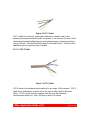
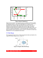
midon design 1-Wire Application Guide 1-Wire Application Guide v1.03 August 9, 2009 1-Wire Application Guide v1.03 Page 1 of 44 midon design Table of Contents List of Tables......................................................................................................3 List of Figures.....................................................................................................3 1 Introduction..........................................................................................................5 2 1-Wire Installations..............................................................................................6 2.1 1-Wire – What is it?.......................................................................................6 2.2 Types of 1-Wire Networks.............................................................................6 2.2.1 Bus Network...........................................................................................6 2.2.2 Star Network...........................................................................................7 2.2.3 Bus and Star Networks...........................................................................9 2.3 How to Wire Networks Properly..................................................................10 2.3.1 Types of interconnect cabling...............................................................10 2.3.2 Connectors or Not?..............................................................................13 2.4 Trouble-Shooting Network Problems..........................................................14 3 Weather Monitoring............................................................................................16 3.1 Types of Weather Sensors..........................................................................16 3.2 Temperature Sensors.................................................................................16 3.2.1 DS18S20..............................................................................................16 3.2.2 DS18S20-PAR......................................................................................16 3.2.3 DS18B20..............................................................................................17 3.2.4 DS1822.................................................................................................17 3.2.5 DS2438.................................................................................................17 3.2.6 Summary..............................................................................................17 3.3 Rain Gauge.................................................................................................18 3.4 Wind Speed.................................................................................................19 3.5 Wind Direction.............................................................................................20 3.6 Humidity Sensor..........................................................................................23 3.7 Barometric Sensor.......................................................................................23 3.8 Lightning Sensor.........................................................................................26 3.9 Solar Sensor................................................................................................27 4 Environmental Sensors......................................................................................29 4.1 Relay Driver.................................................................................................29 4.2 Contact Sensor............................................................................................29 4.3 Counter Sensor...........................................................................................31 4.4 Indicator Sensor..........................................................................................33 4.5 Current Sensor............................................................................................33 4.5.1 HVAC Monitor.......................................................................................34 4.6 1-Wire Devices Not Supported by TEMP08................................................35 4.6.1 Moisture Sensor....................................................................................35 4.6.2 LCD Display..........................................................................................35 4.6.3 1-Wire Hub............................................................................................35 4.6.4 Thermocouple Sensor..........................................................................35 4.7 Sensor Compatibility...................................................................................35 4.8 1-Wire Devices and Availability...................................................................36 5 Connecting To a PC...........................................................................................38 5.1 What software is available..........................................................................38 1-Wire Application Guide v1.03 Page 2 of 44 midon design 5.1.1 HomeSeer.............................................................................................38 5.1.2 DooTemp08..........................................................................................38 5.1.3 Thermd.................................................................................................38 5.1.4 Premise.................................................................................................38 5.1.5 Roll your own........................................................................................38 5.2 Physical connections to a PC......................................................................39 5.3 Trouble-shooting PC problems...................................................................39 6 References.........................................................................................................42 7 Glossary.............................................................................................................43 8 Legal Notices.....................................................................................................44 List of Tables Table 1 RJ-xx Connector Pin-outs........................................................................13 Table 2 ADS Wind Direction Conversion..............................................................22 Table 3 ADS Wind Direction Conversion (Sorted by Voltage).............................22 Table 4 Sensor Compatibility................................................................................36 List of Figures Figure 1 1-Wire Bus Network..................................................................................7 Figure 2 1-Wire Star Network.................................................................................8 Figure 3 1-Wire Star Network with Resistors..........................................................9 Figure 4 1-Wire Bus and Star Network.................................................................10 Figure 5 Telephone Cable....................................................................................11 Figure 6 CAT-1 Cable...........................................................................................12 Figure 7 CAT-5 Cable...........................................................................................12 Figure 8 RJ-12 and RJ-45 Connectors.................................................................14 Figure 9 Sensor Comparisons..............................................................................18 Figure 10 Original 1-Wire Rain Gauge.................................................................18 Figure 11 1-Wire Wind Direction...........................................................................20 Figure 12 Wind Direction Voltages.......................................................................21 Figure 13 1-Wire Humidity Sensor........................................................................23 Figure 14 1-Wire Barometric Sensor....................................................................24 Figure 15 Bray-Jennings Barometer.....................................................................25 Figure 16 Tim Bitson 1-Wire Barometer...............................................................26 Figure 17 Tim Bitson 1-Wire Lightning Monitor....................................................27 Figure 18 Solar Sensor 1......................................................................................28 Figure 19 Solar Sensor 2......................................................................................28 1-Wire Application Guide v1.03 Page 3 of 44 midon design Figure 20 1WIO Input Wiring................................................................................30 Figure 21 Using a 1-Wire Device as a Contact Sensor........................................31 Figure 22 1-Wire Water Meter..............................................................................32 Figure 23 DLJ75C Water Flow Meter...................................................................33 Figure 24 1-Wire Current Sensor..........................................................................34 Figure 25 HyperTerminal Port Settings................................................................40 Figure 26 Location of HyperTerminal Connect Button.........................................41 1-Wire Application Guide v1.03 Page 4 of 44 1 Introduction Thank you for considering Midon Design's 1-Wire Serial interfaces: TEMP08, 1WSwitch and LOG08-II. This application guide has been put together after many, many questions from users about how to connect, what to connect, and how to use, these interfaces. This guide is intended to package all of the common questions (and answers) into one place as a reference for anyone thinking of using 1-Wire®, or even for those that have already implemented systems and want to expand or change it. When applicable, references to TEMP08, 1WSwitch or LOG08-II commands and details are provided. All three products are similar in design but different in capabilities, so please also refer to the product’s user manual for specific information. I would like to thank my colleagues Tim Bitson, Eric Vickery and Aitor Arrieta for their invaluable help in finalizing this document. 1-Wire Application Guide v1.03 Page 5 of 44 2 1-Wire Installations 2.1 1-Wire – What is it? 1-Wire® was a system originally developed by Dallas Semiconductor, now Maxim, to provide an easy way to communicate between microprocessors and peripheral devices using a minimum pin count, hence 1-Wire. 1-Wire devices only require 1 microprocessor pin, and a common ground connection, to achieve bi-directional communication. The 1-Wire system is sometimes also called MicroLAN, or iButton®. The original concept was to provide simplified communications on a single PCB (Printed Circuit Board). With the release of several Sensors Magazine articles by Dallas Semiconductor’s Dan Awtrey in the late 1990’s (see References), however, 1-Wire became a very popular method of providing remote, in other words, off-PCB, sensor data to a microprocessor. This popularity extended to weather station monitoring, which is where TEMP08 has its roots. Without getting too technical, since there are many white papers that get into the technical details already, 1-Wire provides a way of powering and communicating bi-directionally to remote sensors using only two wires, DQ and Ground. Sensor types are discussed later in the guide. 1-Wire powering can be done “parasitically”, that is, at the same time as communications. This is possible since the sensors store the received logic 1 signals as power whenever they are received. 2.2 Types of 1-Wire Networks As for any other kind of network, there are different topologies possible. The two main 1-Wire network types are bus and star. 2.2.1 Bus Network 1-Wire Application Guide v1.03 Page 6 of 44 Figure 1 1-Wire Bus Network A bus network is the simplest kind of network. It consists of a length of cable with sensors tapped into it along the way. Figure 1 shows an example. An advantage of a bus network is it’s electrical simplicity and transmission property performance. Bus networks generally exhibit very little electrical noise, and thus the communications are more robust than star networks. Bus networks are easy to electrically implement as well, however, it is not always convenient to string a cable around to the locations of all sensors required on a bus. Also, bus networks are like the old Christmas light strings – any break anywhere in the bus will cause a fault downstream from the break. Any short on the bus will affect all sensors on the bus. 2.2.2 Star Network 1-Wire Application Guide v1.03 Page 7 of 44 Figure 2 1-Wire Star Network A star network is somewhat more complex than a bus network. A typical star network is shown in Figure 2. An advantage of a star network is that it can be easier to physically wire. Many sensor locations can be reached, and added, by stringing a cable from the main point to the sensor. Also, a break of one sensor’s wiring will not affect other sensors. The biggest disadvantage of a star network, however, is the electrical noise that can be introduced if not properly connected. Electrical noise will result from 1Wire communication pulses traveling down different branches of the star, which generally have different lengths, and returning at different times. This is called reflection. Fortunately, adding a series resistor to all the branches of the network can minimize the reflections. These resistors reduce the reflections, and hence the electrical noise, and therefore make communications somewhat more robust. 1-Wire Application Guide v1.03 Page 8 of 44 Figure 3 shows where the resistors belong. Generally, a 100-ohm resistor is recommended for this. Figure 3 1-Wire Star Network with Resistors 2.2.3 Bus and Star Networks 1-Wire Application Guide v1.03 Page 9 of 44 Figure 4 1-Wire Bus and Star Network Of course, the two main types of network topologies can be combined to achieve required results. Figure 4 shows an example of a properly connected Bus and Star network. Note the locations of the 100-Ohm termination resistors, which are required to minimize noise in the network. Generally, the resistors should be placed at every branch of the network. 2.3 How to Wire Networks Properly 2.3.1 Types of interconnect cabling There are several types of cables that can be used for 1-Wire networks. The one you choose will depend on your application. 2.3.1.1 Telephone (flat) cable 1-Wire Application Guide v1.03 Page 10 of 44 Figure 5 Telephone Cable This is the kind of cable that is used to plug your telephone into a phone jack. It normally has 4 wires, but some only have 2 and some have 6 wires. You do not usually need more than 2 wires for just temperature sensing, but some other types of sensors will definitely need 3 or more wires, so consider this before permanently wiring your network. Telephone cable is not recommended for networks that span more than 50 feet or so. The Red and Green wires of telephone cable are recommended for connection to DQ (red) and Ground (green) on the 1-Wire bus. Note: if you are using pre-connectorized telephone cable, check that the wires connecting both connectors are “straight-through”. Most pre-connectorized cables have the red and green wires (and the yellow and black wires) reversed between connectors. 2.3.1.2 CAT-1 Cable 1-Wire Application Guide v1.03 Page 11 of 44 Figure 6 CAT-1 Cable CAT-1 cable is 4 conductor twisted pair cable that is usually used to wire between phone jacks inside the walls of a house. It can be used for most 1-Wire networks and usually exhibits decent noise performance for networks less than around 100 feet. Use the Red/Green wires for DQ and Ground. Use the Yellow and Black wires for remote power if needed. 2.3.1.3 CAT-5 Cable Figure 7 CAT-5 Cable CAT-5 cable is the preferred wiring method for any large 1-Wire network. CAT-5 cable has 4 twisted pairs of wires and is the type of cable used for Ethernet wiring. CAT-5 can be used for networks that are up to the maximum recommended reach for 1-Wire: 300 feet or about 100 meters. 1-Wire Application Guide v1.03 Page 12 of 44 Use the Blue-White wire for DQ, and the White-Blue wire for Ground. Powering can be done over any of the other pairs. Pick a pair and then stick to it for all your wiring to avoid mistakes in wiring later. 2.3.2 Connectors or Not? Most 1-Wire sensors sold by all the vendors today come equipped with modular connectors, either RJ-11, RJ-12 or RJ-45. Most sensors also come equipped with some kind of screw-in connector as well, for terminating wires. The choice of using a connectorized scheme for your network is yours and will be based on several factors. If you plan to relocate sensors a lot, then connectors are the way to go. If not, then connectors may not make much sense. Using connectors implies that all wiring is terminated with mating connectors. This may work for simple networks, but may be too much trouble for larger, more complex networks. If you do choose to use connectors, keep in mind that, while there is now a standard for connector pin-outs, all vendors use slightly different variations for pin-outs, simply due to the lack of standard when the sensors were first developed, so be very careful when mixing different vendor’s sensors on a network. Here is a cross-reference table for some popular connector schemes. Table 1 RJ-xx Connector Pin-outs Device Original Dallas Weather Station AAG RJ-11 Sensors/Interfaces Dallas/Maxim RJ12 wiring standard (published Oct 2001) Midon Design MD2104 TEMP08/LOG08II/1WSwitch Midon Design Sensors AAG RJ-12 Pin 1 Pin 2 Pin 1 Pin 3 Pin 2 Pin 1 N/C Pin 4 Pin 3 Pin 2 DQ Pin 5 Pin 4 Pin 3 GND Pin 6 Pin 5 Pin 4 N/C GND DQ GND +5VDC +5VDC GND DQ GND N/C DC Supply RJ-12 DC +5VDC Supply DQ GND N/C N/C RJ-12 DC +5VDC Supply +5VDC GND DQ GND N/C N/C RJ-12 DQ GND N/C N/C RJ-12 1-Wire Application Guide v1.03 Pin 7 Pin 6 Pin 8 RJ-45 RJ-12 RJ-11 RJ-11 RJ-11 Page 13 of 44 Sensors Texas Weather N/C GND DQ GND Instruments sensors Simon Atkins’ Hub +5VDC +5VDC DC DQ GND Supply AAG RJ-45 DQ GND +5VDC +12VDC +12VDC Sensors Hobby-Boards GND +5VDC GND DQ GND Sensors 1Wire.org draft GND +5VDC GND DQ GND standard for RJ45 N/C DC Supply DC Supply +5VDC GND GND RJ-45 GND GND RJ-45 +12VDC GND RJ-45 Analog +12VDC GND Signal RJ-45 N/C RJ-12 RJ-11 refers to the common 4-pin telephone plug. RJ-12 is the less common equivalent plug that has 6 pins equipped. RJ-45 is the common 8-pin Ethernet plug. Pin numbers in the table above presume that Pin 1 of the female connector is on the left when facing it and the spring latch is on the bottom as in Figure 8. Figure 8 RJ-12 and RJ-45 Connectors 2.4 Trouble-Shooting Network Problems There are many components to a 1-Wire network, including the PC, the PC Serial Port, PC software, the 1-Wire interface, the sensors, and the wiring. As a result, trouble-shooting needs to be done in a methodical way, starting at basics and then building up to the point where trouble begins. In a TEMP08 system, start by making sure that TEMP08 is alive and well. If the green light is flashing, and goes red from time to time, then TEMP08 is functioning. Disconnect all your sensors from TEMP08 now. Connect TEMP08 now to a PC running a terminal emulation program, such as HyperTerminal, which comes with every Windows PC. Make sure that you can 1-Wire Application Guide v1.03 Page 14 of 44 communicate to TEMP08 by trying a few commands and then verifying that the responses come back. If this isn’t working, check the settings on your serial port and the connections between the serial port and TEMP08. See the Troubleshooting PC Problems section later in this manual for other considerations. Issue a TMP command now and make sure that the on-board 1-Wire sensor is reporting back correctly. If it is, proceed to the next steps. If it is not, then something may have damaged the 1-Wire interface to TEMP08 and it may have become defective. Return to Midon Design for repair, if necessary. Now, connect one branch of your star network at a time to TEMP08. If you are using a simple bus network, go ahead and re-connect it. Any problems? If so, physically disconnect, one at a time, any sensors that indicate error readings. Have the problems gone away when any one sensor is disconnected? If so, disconnect all sensors again and then reconnect that one sensor directly to TEMP08 with a short piece of cable. Does the sensor still give a problem? If so, you have a defective sensor. If not, there is a wiring problem to the original location of that sensor: fix it before proceeding. Don’t forget to check for power wiring problems! TEMP08 will report a short on the 1-Wire bus by issuing a “OW Bus Error” message. If you see that at any time in this process, then consider the possibility that a sensor is installed “backwards”; in other words, DQ and Ground are reversed for that sensor. Also, consider the possibility that a short does exist in your wiring, OR, although highly unlikely, a sensor has become completely defective and is shorting out the bus. Follow the above steps for all branches of your network. If the steps above did not resolve the problem, and you are running a star network, the problem might be a result of reflections. If you do not have 100Ohm resistors in the branch feeds, now would be a good time to insert them and re-test your set-up. Assuming that everything is now working, close HyperTerminal and restart your PC software. If no problems, wonderful! If you are still having problems, report them to the author of your PC software. 1-Wire Application Guide v1.03 Page 15 of 44 3 Weather Monitoring 3.1 Types of Weather Sensors 1-Wire weather sensors are available from a variety of vendors, including, of course, Midon Design. All the standard weather parameters can be monitored with the sensors. The following sections will describe the available sensors, and the theory of operation of the sensors. It should be noted that most, of these sensors might be mounted outdoors, so be careful with how you mount them and most importantly about the wiring. An ever-present danger about wiring outdoors is exposure to the elements and increased exposure to potential lightning strikes. As a general rule you should disconnect all the sensors whenever lightning is nearby. If you are mounting your sensors outdoors, also be very aware of any nearby power wires and avoid them. 3.2 Temperature Sensors There are different types of temperature sensors available for 1-Wire applications. These include: 3.2.1 DS18S20 This is the ubiquitous sensor and available in many mounting options, ranging from the bare device to sealed enclosures with connectors. The DS18S20 offers 9-bit resolution, or a ± 0.5°C precision. Temperatures can be measured from –55°C to +125°C (-67°F to +257°F). Accuracy is ± 0.5°C (± 0.9°F) from –10°C to +85°C. 3.2.2 DS18S20-PAR The DS18S20-PAR is identical in performance to the DS18S20, except that it will only operate in parasitic powering mode. The Vdd pin is not connected on this device and is internally connected to the GND pin. This device is not normally 1-Wire Application Guide v1.03 Page 16 of 44 seen in enclosures or connectorized modules and is best suited for on-board temperature sensing. 3.2.3 DS18B20 The DS18B20 offers 9, 10, 11 or 12 bit resolution, or ± 0.5°C, ± 0.25°C, ± 0.125°C or ± 0.0625°C precision respectively. Temperatures can be measured from –55°C to +125°C (-67°F to +257°F). Accuracy is ± 0.5°C (± 0.9°F) from – 10°C to +85°C. TEMP08 uses this device in 12-bit resolution mode. Note: Waterproof DS18B20 sensors are available from RFXCOM Products at http://www.rfxcom.com/sensors.htm#Additional. These sensors can be used for pool, hot tub, or aquarium temperature monitoring. 3.2.4 DS1822 The DS1822 offers 9, 10, 11 or 12 bit resolution, or ± 0.5°C, ± 0.25°C, ± 0.125°C or ± 0.0625°C precision respectively. Temperatures can be measured from – 55°C to +125°C (-67°F to +257°F). Accuracy is ± 2.0°C (± 3.6°F) from –10°C to +85°C. TEMP08 uses this device in 12-bit resolution mode. 3.2.5 DS2438 Even the DS2438 has temperature-sensing capability. It offers 13-bit resolution, or a ± 0.03125°C precision. Temperatures can be measured from –55°C to +125°C (-67°F to +257°F). Accuracy is ± 2.0°C (± 3.6°F) from –40°C to +85°C. To use the DS2438 for temperature only, set the DS2438 type to “T” (temperature). 3.2.6 Summary 1-Wire Application Guide v1.03 Page 17 of 44 0.6 Precision 0.5 Accurary 2.5 2 0.4 1.5 0.3 1 0.2 0.5 DS2438 DS1822 DS18B20 0 DS18S20 0.1 0 Figure 9 Sensor Comparisons There are lots of choices for temperature sensors available and all have slightly different characteristics. Your choice might depend on accuracy or precision, or a combination of both (see Figure 9). Be careful not to confuse the two. Precision is the resolution of the measurement, but accuracy is the variance between the actual temperature and the returned result. Many users have confused this and have been puzzled why two devices placed side by side would produce a variance in temperature. Look at the worst case: two devices, each with a precision of ±0.5°C and an accuracy of ±2.0°C, could lead to a worse case difference of 5°C (9°F) between the two sensors. 3.3 Rain Gauge All rain gauges developed for the 1-Wire measurement scheme are based on the original Dan Awtrey design shown in Figure 10. Figure 10 Original 1-Wire Rain Gauge 1-Wire Application Guide v1.03 Page 18 of 44 The rain gauge counts rainfall via a tipping bucket, which is magnetically coupled to the reed switch SW1. The original design called for a tipping bucket design, which caused a tip to occur for every 0.01 inch of rainfall. The DS2423 inputs A and B are connected to an internal counter, which will then increment for every 0.01 inch of rain. Rain gauges are still available from some vendors in this original configuration. Also, some vendors have developed a retrofit kit for non-1-Wire rain gauges to allow them to be read from a 1-Wire interface. There are many wireless or wired rain gauges that can be retrofitted in this manner. When used with TEMP08, set the DS2423 type to “R” (rain). 3.4 Wind Speed Some Wind Speed sensors available are based on the same 1-Wire circuit as the rain gauge. The reed switch is coupled to an anemometer vane, which rotates with a speed proportional to the speed of the wind flowing through the cups. The original wind speed sensor from Dallas Semiconductor used only 1 reed switch, however, later versions, such as those formerly available from AAG, and previously from Hobby Boards, used 2 reed switches, which meant that the counters were incremented twice as often as the original design. TEMP08 is designed to work with the later versions only. If you are not sure which are supported, contact Midon Design. When used with TEMP08, set the DS2423 type to “W” (wind). Only one wind speed counter is supported on TEMP08. Hobby Boards now sells the Inspeed and ADS Anemometers. Wind speed is provided with DS2423 counters, however, in a different format than previous 1Wire Anemometers. To use these sensors, set TEMP08 to “L” (Lightning) and calculate the wind speed via the formulae below. Inspeed Anemometer: Wind Speed = (2.5 x Count) / Time ADS Anemometer: Wind Speed = (1.5 x Count) / Time Where: Wind Speed = speed in miles per hour Count = the current counter reading less the previous counter reading 1-Wire Application Guide v1.03 Page 19 of 44 Time = the time since the last reading 3.5 Wind Direction There are two main variations of the original 1-Wire wind direction sensors. The original design used reed switches connected via DS2401 1-Wire serial numbers to denote the position of the wind. The second, and last 1-Wire version supported by TEMP08, uses reed switches connected via voltage dividers to a DS2450 Quad ADC device, as per Figure 11. Figure 11 1-Wire Wind Direction Wind direction then becomes defined by the voltages reported from the DS2450 as per the table in Figure 12. 1-Wire Application Guide v1.03 Page 20 of 44 Figure 12 Wind Direction Voltages Of course, knowing which position is not enough. You need to know which position is North, East, West, etc. TEMP08 has the NOR command available to be able to set the North position. Once that has been done, the other positions are known and wind direction is now absolute. There are two conditions when West might become East, and vice versa; if you install the PCB upside down (easy to do!) and when you would rather know where the wind is blowing from rather than blowing to. TEMP08 offers the REV command to flip East and West, and all the other cardinal points, to do this. There are now new wind direction sensors on the market that use DS2438’s to determine direction. These are not directly compatible with TEMP08 wind conversions, however, can still be used if the DS2438 type is set to “V” (voltage). Translation of the voltage to wind direction will need to be done by the PC connected to TEMP08. Hobby Board sells both the Inspeed and ADS wind direction sensors based on DS2438’s. To calculate the wind direction for the Inspeed sensor use the following formula: 1-Wire Application Guide v1.03 Page 21 of 44 D = 400 x (VAD – 0.05 x VDD) VDD Where: D=wind direction in degrees VAD=wind vane output voltage VDD=supply voltage To calculate the wind direction for the ADS sensor use the following Table(s): Table 2 ADS Wind Direction Conversion Direction N NNE NE ENE E ESE SE SSE S SSW SW WSW W WNW NW NNW Voltage 2.66-2.72 6.49-6.55 5.96-6.02 9.35-9.41 9.27-9.33 9.50-9.56 8.48-8.54 8.98-9.04 7.57-7.63 7.95-8.01 4.28-4.34 4.59-4.65 0.89-0.95 2.20-2.26 1.54-1.60 3.54-3.60 Table 3 ADS Wind Direction Conversion (Sorted by Voltage) Direction W NW WNW N NNW SW WSW NE NNE S SSW SE 1-Wire Application Guide v1.03 Voltage 0.89-0.95 1.54-1.60 2.20-2.26 2.66-2.72 3.54-3.60 4.28-4.34 4.59-4.65 5.96-6.02 6.49-6.55 7.57-7.63 7.95-8.01 8.48-8.54 Page 22 of 44 SSE E ENE ESE 8.98-9.04 9.27-9.33 9.35-9.41 9.50-9.56 3.6 Humidity Sensor Figure 13 1-Wire Humidity Sensor All 1-Wire humidity sensors are based on the original design shown in Figure 13. Variations over time have occurred since Honeywell has discontinued the original HIH3610 humidity sensor and replaced it with the HIH4000 and later with the HIH402x variations. The humidity sensor produces a voltage proportional to the Relative Humidity, which is then read by the DS2438 ADC and converted to digital format. Care needs to be taken with placing these sensors outdoors since the Honeywell HIH3610 and HIH4000 sensors will fail over time if exposed to condensing humidity environments. Honeywell produced the HIH4021 sensor, which is sealed, to avoid these failures. Indoor placement is also critical – don’t install non-HIH4021 sensors in a wet environment, for example a bathroom shower, since the humidity sensor will eventually fail. Most of the sensor connectors will eventually corrode if exposed to high humidity or corrosive environments, which will lead to false or missing readings. When used with a TEMP08, set the DS2438 type to “H” (humidity). 3.7 Barometric Sensor 1-Wire Application Guide v1.03 Page 23 of 44 An important weather parameter is air pressure. The absolute reading is not nearly as significant as the change in the reading, since rising or falling air pressure will indicate a change in weather. Figure 14 1-Wire Barometric Sensor Figure 14 shows the original concept design of a barometric sensor. This design was not overly practical since the working range of the Motorola pressure sensor used was very narrow, so David Bray and Jim Jennings modified the design to be the one shown in Figure 15. 1-Wire Application Guide v1.03 Page 24 of 44 Figure 15 Bray-Jennings Barometer This design was modified slightly over time, and the currently available production unit is shown in Figure 16. The operating principle remained the same over all versions of the design. 1-Wire Application Guide v1.03 Page 25 of 44 Figure 16 Tim Bitson 1-Wire Barometer The Motorola MPX4115 device outputs a voltage proportional to the air pressure. This voltage is scaled up by the amplifier(s) to be within a useable range for the DS2438 ADC and then converted to digital on the 1-Wire bus. These devices do not need to be placed outdoors. Unless you have an extremely airtight building, the air pressure indoors will always be the same as the air pressure outdoors. When used with a TEMP08, set the DS2438 type to “B” (Barometer). 3.8 Lightning Sensor 1-Wire Application Guide v1.03 Page 26 of 44 Figure 17 Tim Bitson 1-Wire Lightning Monitor Tim Bitson (see References) designed the original 1-Wire Lightning Monitor shown in Figure 17. The 1-Wire side of the design is the same as the rain gauge and wind speed sensor, in other words a DS2423 counter. The input to the counter is not a reed switch, but rather an amplified antenna pickup. Any lightning strikes occurring within range of the antenna will be amplified by Q1 and Q2 and then presented to the DS2423 counter input, which will register the strike as a count. These counts are then reported over the 1-Wire bus when the DS2423 is interrogated. Great care should be taken with this sensor to 1. Properly ground it, and 2. Disconnect it whenever lightning is too close. Lightning is very unpredictable and the last thing you want is to have high voltage surge through your sensor back to your PC or elsewhere in your house. When used with the TEMP08, set the DS2423 type to “L” (lightning). 3.9 Solar Sensor 1-Wire Application Guide v1.03 Page 27 of 44 Figure 18 Solar Sensor 1 Figure 19 Solar Sensor 2 As can be seen from the figures above, there are two types of solar sensor designs. The Solar Sensor 1 design in Figure 18 is the more common one. Both designs work on the same principle however. Light falling on the sensor, either a solar cell or a photodiode, causes a small voltage to appear at the Vs inputs of the DS2438. These inputs are normally used in DS2438 battery monitoring applications to measure current flow, however, they work equally well in this application. The amount of light will be proportional to the voltage at the inputs; so reading the DS2438 Vs voltage will determine how much light is present. Obviously, these sensors need to be mounted outdoors to be able to determine solar radiation. Place them in a position where sunlight is present and rain will not fall directly on the sensor. When used with a TEMP08, set the DS2438 type to “V” (voltage). 1-Wire Application Guide v1.03 Page 28 of 44 4 Environmental Sensors 4.1 Relay Driver Midon Design offers 2 types of 1-Wire relay drivers. 1. 1WIO, which has 4 SPDT relays, and 2. MD3020G, which has one SPDT relay. The 1WIO is DS2408 based and up to 40 of these devices are supported on TEMP08. When using the 1WIO in relay mode (it is also available as an input device), make sure to turn off input sensing by the EIN OFF command to avoid false readings from the DS2408. 1WIO is supported by both TEMP08 and 1WSwitch. The MD3020G is DS2406 based. It is no longer supported by TEMP08, but is supported by TEMP08’s sister product, the 1WSwitch. Relay drivers are useful to interface with non-1-Wire devices that need simple on/off functionality, such as sprinkler systems, alarm systems, low voltage lighting, X10 Powerflash interfaces, etc. The relays used on both of these sensors should not normally be directly connected to mains power for safety reasons, but can easily be connected to other relays to operate mains powered devices. The SPDT contacts provide for Normally Open (NO) and Normally Closed (NC) contacts. A NO contact is open when power is not applied to the relay, and a NC contact is closed when power is not applied. Both contacts are referenced to the Common (C) connection of the relay. 4.2 Contact Sensor Contact sensors are used to determine the state of a contact. Midon Design offers the 1WIO as a 4 contact input device. Wiring of the contacts can be done as shown in Figure 20. When using the 1WIO as in input device, make sure that you enable the input functionality by the EIN ON command. 1-Wire Application Guide v1.03 Page 29 of 44 Figure 20 1WIO Input Wiring Up to 40 1WIO’s can be connected to TEMP08 in this manner. Mixing input and LED versions of 1WIO on TEMP08 can be tricky since connecting at least 1 1WIO input device will require the use of the EIN ON command, which will cause issues with 1WIO LED devices in some early versions of TEMP08 software. The top 4 LED’s on a 1WIO LED device would blink out when EIN ON is set on TEMP08. If this occurs, consider upgrading your TEMP08 software. Another way to determine the status of a contact is to use the trick that Dallas Semiconductor originally used for the 1-Wire Wind Direction Sensor; place the contact switch between the DQ line and any sensor’s DQ input per Figure 21. Whenever the contact, SW1, is open, TEMP08 will report the corresponding sensor U1 as “missing”. When the contact closes, TEMP08 will report the sensor as “present”. 1-Wire Application Guide v1.03 Page 30 of 44 Figure 21 Using a 1-Wire Device as a Contact Sensor 4.3 Counter Sensor Counter sensors are useful for measuring any changing parameter that is provided via contact closure, such as water flow meters, some electrical meters, etc. Counter sensors are generally DS2423 based, and if so are directly compatible with TEMP08. Set the DS2423 type to “C” (counter) when used in this mode. A Water Meter counter example is shown in Figure 22. 1-Wire Application Guide v1.03 Page 31 of 44 Figure 22 1-Wire Water Meter In Figure 22, the Flow counter could be as shown in Figure 23, a DLJ75C pulse counting water meter from www.watermeters.com , which registers one pulse per gallon of water flowing through the meter. 1-Wire Application Guide v1.03 Page 32 of 44 Figure 23 DLJ75C Water Flow Meter 4.4 Indicator Sensor Midon Design offers two LED indicator devices, which might be useful for displaying the state of something remotely via the 1-Wire network. One sensor, the MD3020H, is DS2406 based and is supported by the 1WSwitch and earlier versions of TEMP08. It has one LED on board which can be set on or off. The other sensor is the 1WIO LED driver, which has 8 LED’s on board, individually controlled by the LEDxx command. Up to 20 1WIO LED devices can be supported on TEMP08, or 1WSwitch. As for the 1WIO relay device, you must set EIN OFF when using this device with TEMP08 or 1WSwitch. 4.5 Current Sensor Current sensors can be used to measure mains current flow, which is useful to determine how energy is being used for a device or a residence. A current sensor can be fabricated by connecting the parts shown in the schematic of Figure 24 to a DS2438 or DS2450 ADC (Analog to Digital Converter). TEMP08 can then read the voltage of the circuit, which will be directly proportional to the current flowing through whatever wire the CT3110 current probe is clamped on to. The CT3110 current probe is available from Midon Design. 1-Wire Application Guide v1.03 Page 33 of 44 Resistor R1 in Figure 24 can be chosen by the formula R1 = V x 3100 / I Where V = 10 Volts (the maximum input to a DS2438) x 1.414 (scaled to DC) = 14.14 Volts And I = the maximum expected current on the circuit being measured. As an example, if you expect to see no more than 20 Amps on a circuit, then R = 14.14 x 3100 / 20 = 2192Ω 2192 is not a standard value resistor, so you can use a variable resistor to achieve this value, or simply use the next closest value. In this case, that would be a 2200 Ω resistor. Figure 24 1-Wire Current Sensor 4.5.1 HVAC Monitor Eric Vickery at Hobby Boards has designed a general-purpose voltage monitor, based on the DS2450 Quad ADC, which can be used, amongst other things to monitor your HVAC system. This sensor is compatible with TEMP08. If you are using this device without having a wind direction sensor installed on the same bus, make sure to disable wind direction reporting (which will allow the voltages from the DS2450 to be visible) by using the EWN OFF command. 1-Wire Application Guide v1.03 Page 34 of 44 4.6 1-Wire Devices Not Supported by TEMP08 4.6.1 Moisture Sensor Moisture sensors are available from some vendors as a DS2760-based device. These devices are not compatible with TEMP08, however. Similar sensors can be built using a DS2438 current sensor input, which would be supported by TEMP08. A Leaf Wetness Sensor is also available. It is not directly 1-Wire compatible, but is connected through a Moisture Sensor, which means that it is not compatible with TEMP08. 4.6.2 LCD Display LCD display devices are available from some vendors with a DS2408-based 1Wire interface. There is no multi-vendor standard for this interface however and TEMP08 does not support it. 4.6.3 1-Wire Hub The 1-Wire Hub is a DS2409-based design and was originally conceived by Simon Atkins (see References). This hub is typically used for very complex networks of star and bus design, however is not always required. TEMP08 does not support this device. 4.6.4 Thermocouple Sensor AAG has a thermocouple sensor, which might be used to measure temperatures much above the normal 1-Wire temperature sensor capability. Since this sensor is based on the DS2760, it is not compatible with TEMP08. 4.7 Sensor Compatibility Table 2 shows which sensors are compatible with our various products. NOTE: the sensor compatibility does not imply that the connector pin-outs are equivalent, only that the sensor is capable of being read and parameters displayed. 1-Wire Application Guide v1.03 Page 35 of 44 Table 4 Sensor Compatibility Sensor DS18S20 Temperature TEMP08 Compatibility 1WSwitch LOG08-II Midon Design Y N DS18S20-PAR Temperature Y N DS18B20 Temperature Y N DS1822 Temperature Y N DS2438 Voltage & Current Y Y DS2423 Rain Gauge Y N DS2423 Wind Speed Y N DS2450 Wind Direction Y N DS2450 Voltage Y N DS2438/DS2423 Wind Y (Note 1) N Speed/Direction DS2438 Humidity Sensor Y Y (Note 1) DS2438 Barometric Sensor Y Y (Note 1) DS2423 Lightning Sensor Y N DS2438 Solar Sensor Y Y DS2408 4 Relay Driver Y Y DS2406 1 Relay Driver Y Y DS2408 4 Contact Sensor Y Y DS2423 Counter Sensor Y N DS2408 8 LED Indicator Y Y DS2406 1 LED Indicator Y Y DS2438 Current Sensor Y (Note 1) Y (Note 1) DS2760 Moisture Sensor N N DS2760 Leaf Wetness Sensor N N DS2408 LCD Display DS2409 1-Wire Hub DS2450 HVAC Monitor DS2760 Thermocouple Sensor N N Y N N N Y MD3003, MD3020B, MD3020C Y Y Y Y MES1276 Y (Note 1) N N Y Y (Note 1) Y Y (Note 1) Y Y N N N Y N N Y (Note 1) N N N N Y MD3020E MD2083 MD3020G MD2084 Sources AAG Hobby Boards TAI8520 T3-R1-A DS18S20-P DS2438Z-P RG1-R1-A WIND-ADS-A or WIND-IN-A TAI8540D H3-R1-A B1-R1-A LD4-R1-A S3-R1-A TAI8558 8CIO4-R1-A TAI8558 8CIO4-R1-A DC2.5-R1-A MD2088 MD3020H MM2-R1-A LWS1-R2-B AND MM2-R1A TAI8590 TAI8595 LCD2-R1-A 6CMH1-R3-A HVAC2-R1-A N N N TAI8560 DS2406 Barometric Sensor N N N TAI8570 Note 1: Compatibility is limited to being able to read the raw data. Conversion to specific weather data is left to the user. 4.8 1-Wire Devices and Availability 1-Wire Application Guide v1.03 Page 36 of 44 Unfortunately, Dallas Semiconductor, now known as Maxim, has begun to phase out some of the semiconductors used in 1-Wire sensor devices. Most production houses have a fairly large supply of these critical components, however, check first before designing in any specific sensor. As of the writing of this manual, the following devices are no longer available directly from Dallas/Maxim: • • • DS2423 Counter (no replacement available) DS2405 Switch (editorial note: good! This was a very finicky device!) Similar functionality is available from the DS2406 or DS2413. DS2760 Battery monitor (replaced by the DS2762) 1-Wire Application Guide v1.03 Page 37 of 44 5 Connecting To a PC 5.1 What software is available 5.1.1 HomeSeer HomeSeer is perhaps the most popular method of interfacing to TEMP08. HomeSeer is available at www.homeseer.com and interface scripts and plug-ins are available on the HomeSeer Forum. Midon Design also provides a simple script interface on our website. Jim Doolittle, Ken Mitchell and Michael McSharry have written HomeSeer plugins for TEMP08. These are available from the Forum or direct from the authors. 5.1.2 DooTemp08 DooTemp08 is a stand-alone software program that can also be used as a HomeSeer plug-in. It is available at Jim Doolittle’s website. 5.1.3 Thermd Thermd is a free software program developed by David Klein that can also interface to TEMP08. It is available at http://www.klein.com/thermd. This software is written in Perl and the source code is provided on David’s website. 5.1.4 Premise Ken Mitchell and ”123” have, as of the writing of this guide, started writing a TEMP08 interface program for the Premise home control system. They are discussing it on CocoonTech’s forum. 5.1.5 Roll your own You can, of course, always write your own software to interface to TEMP08. What you need is software to read and write to a serial port on your PC and to interpret the returned results. All TEMP08 commands are documented in the User Manual. Output examples are also provided there. 1-Wire Application Guide v1.03 Page 38 of 44 5.2 Physical connections to a PC A straight-through, not null modem, serial cable connects between the TEMP08 and your PC's serial port. Straight-through simply means that all pins of the connectors on each end are the same, pin 1 of one connector is cabled to pin 1 of the second connector, pin2 to pin 2, etc. One connectors needs to be a DB-9 Male connector to fit the TEMP08, and the other connector needs to be a DB-9 Female connector to fit the PC. In case you want to make your own cable, TEMP08 only uses the TX (pin 2), RX (pin 3) and Ground (pin 5) pins of an RS232 cable to communicate. The RS232 settings should be 9600 bps, no parity, eight bits, with no flow control. RS232 cables should not be longer than 50 feet (about 15 meters) for proper communication at the 9600 bps rate used. 5.3 Trouble-shooting PC problems As a first step to trouble-shooting PC or software problems, you want to make sure that your PC can properly communicate with TEMP08. HyperTerminal, which comes with every Windows based PC, can be used to monitor communications with TEMP08. HyperTerminal is usually located in the Windows Start folder under Accessories/Communications. Figure 25 shows what the settings should look like (COM3 shown in this example – choose your COM port to match the RS232 connection to TEMP08): Once you have made the connection to a PC, and set up HyperTerminal to properly communicate with TEMP08, make sure you can communicate with TEMP08 by entering HLP, or any other command. You should see a response from TEMP08 similar to what is shown in the current user manual for the command you entered. If you can communicate in this way to TEMP08, then shut down HyperTerminal (to free the RS232 port for other use) and try running your software again. If you are unable to communicate with TEMP08 with HyperTerminal, then check the following: 1. Is the cable connecting TEMP08 to the PC a straight-through cable? Check the wiring to make sure. 2. Is the cable plugged in properly at both ends? 1-Wire Application Guide v1.03 Page 39 of 44 3. Are the RS232 port settings properly configured (see Figure 25)? 4. Is HyperTerminal “connected”? See Figure 26 for the location of the Connect button – click on that button to enable the connection between your PC and TEMP08. 5. Is TEMP08 properly powered? The Green LED next to the RS232 connector should be flashing once per second. Note: it might flash red from time to time, but that is OK. Figure 25 HyperTerminal Port Settings If your software is still unable to work properly with TEMP08, please contact the author of the software and make sure that you include any HyperTerminal session logs to illustrate your problems. It is possible that TEMP08 command or response syntax is different than the version the author originally coded from. 1-Wire Application Guide v1.03 Page 40 of 44 Figure 26 Location of HyperTerminal Connect Button 1-Wire Application Guide v1.03 Page 41 of 44 6 References 1. “Transmitting Data and Power over a One-Wire Bus”, Dan Awtrey, Sensors Magazine, February 1997 http://archives.sensorsmag.com/articles/0297/onewire/index.htm 2. “The 1-Wire Weather Station”, Dan Awtrey, Sensors Magazine, June 1998 http://archives.sensorsmag.com/articles/0698/wir0698/index.htm 3. “A 1-Wire Rain Gauge”, Dan Awtrey, Sensors Magazine, December 1999 http://archives.sensorsmag.com/articles/1299/56_1299/index.htm 4. "A 1-Wire Humidity Sensor", Dan Awtrey, Sensors Magazine, August 2000 http://archives.sensorsmag.com/articles/0800/62/index.htm 5. "1-Wire Addressable Digital Instruments for Environmental Monitoring", Dan Awtrey, Sensors Magazine, May 2001 http://archives.sensorsmag.com/articles/0501/34/index.htm 6. “An Experiment’s 1-Wire Barometer”, David Bray http://davidbray.org/onewire/barometer.html 7. “1-Wire Lighting Monitor”, Tim Bitson, December 2001 http://www.timbitson.com/Weather_Projects_files/owlm.pdf 8. “iButton 1-Wire Hub”, Simon Atkins http://www.simat.org.uk/1wirehub.html 9. AAG Web Site: www.aag.com.mx 10. Hobby Boards Website: www.hobby-boards.com 1-Wire Application Guide v1.03 Page 42 of 44 7 Glossary Term ADC DQ GND LCD LED NC NO PC PCB Plug-In RX SPDT TX VAC VDC 1-Wire Application Guide v1.03 Description Analog to Digital Converter The input/output connection on a 1Wire bus Ground Liquid Crystal Display Light Emitting Diode Normally Closed Normally Open Personal Computer Printed Circuit Board An program added into to a master software program to add functionality Receive Single Pole Double Throw – a type of relay or switch contact Transmit Volts Alternating Current Volts Direct Current Page 43 of 44 8 Legal Notices © Copyright 2009 Midon Design. All rights reserved. No part of this document may be reproduced, recorded, transmitted or distributed in any form or by any means without the written consent of Midon Design. 1-Wire is a registered trademark of Maxim Integrated Products, Inc. MicroLAN is a trademark of Maxim Integrated Products, Inc. iButton is a registered trademark of Maxim Integrated Products, Inc. End of Document 1-Wire Application Guide v1.03 Page 44 of 44