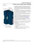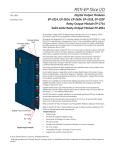
1
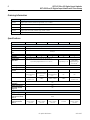
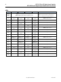
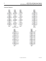
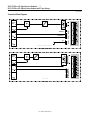
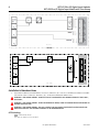
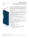
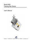
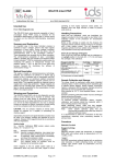
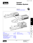
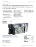
RSTI-EP Slice I/O Digital Input Modules EP-1214, EP-1218, EP-1318, EP-125F Digital Input Module with Time Stamp EP-12F4 GFK-2957 November 2015 Module Status LED Channel Status LEDs GE provides a range of RSTi-EP digital input modules with 4, 8 or 16 inputs, which are primarily used to receive binary control signals from sensors, transmitters, switches or proximity switches. Their flexible design allows them to meet your demands with reserve potential. All modules are fully compliant with IEC 61131-2. They can be switched on the input side with type-1 and type-3 sensors in accordance with IEC 61131-2. The wiring connectors on each module are color coded for ease of wiring. Refer to the section, Field Wiring for additional information. The time stamp module EP-12F4 can detect up to 4 binary control signals and provide them with a time stamp (resolution 1 μs). Depending on the configuration of the module, up to 5 or 15 time stamp entries can be evaluated. Each module features a type plate, which includes identification information, the key technical specifications, and a block diagram. In addition, a QR code allows for direct online access to the associated documentation. The software for reading the QR code must support inverted QR codes. Markers are available as accessories for labelling equipment. Each I/O module can be labelled using the markers to ensure clear identification when replacing individual modules or electronic units. A green Module Status LED indicates there is communication on the system bus. Additionally, there are Yellow LEDs for each input to indicate when it is active. Refer to the section, LEDs for additional information. The RSTi-EP station is usually installed on a horizontally positioned DIN rail. Installation on vertically positioned DIN rails is also possible. Modules should to be allowed to de-energize for a minimum 10 seconds after power down, prior to starting any maintenance activity. Refer to the RSTi-EP Slice I/O Module User Manual (GFK-2958) for additional information. Refer to the RSTi-EP Power Supply Reference Guide, a software utility available on PME V9.00, for detailed power-feed requirements. Digital Input Connector Ground 24 V DC FE Digital Input Module Module Features Positive Logic Spring style technology for ease of wiring DIN rail mounted Double-click installation for positive indication of correct installation Up to 16 sensor inputs Compatible with type-1 and type-3 sensor inputs per IEC 61131-2 Time stamping available Supports hot insertion and extraction © 2015 General Electric Company. All Rights Reserved. * Indicates a trademark of General Electric Company and/or its subsidiaries. All other trademarks are the property of their respective owners. 2 RSTi-EP Slice I/O Digital Input Modules RSTi-EP Slice I/O Digital Input Module with Time Stamp GFK-2757 Ordering Information Module Description EP-1214 Digital Input, 4 Points, Positive Logic 24VDC, 2,3, or 4 Wire EP-1218 Digital Input, 8 Points, Positive Logic, 24VDC 2 Wire EP-1318 Digital Input, 8 Points, Positive Logic, 24VDC 3 Wire EP-125F Digital Input, 16 Points, Positive Logic, 24VDC, 1 Wire EP-12F4 Digital Input, 4 Points, Positive Logic 24VDC, 2,3, or 4 Wire, Time stamp Specifications EP-1214 System Data Data Interface System bus transfer rate Inputs Channels Sensor types Input filter Off voltage On voltage Max. input current per channel Sensor supply Sensor connection Reverse polarity protection Module diagnostics Individual channel diagnosis Supply Supply voltage Current consumption from system current path ISYS Current consumption from input current path IIN EP-1218 EP-1318 EP-125F EP-12F4 Process, parameter and diagnostic data depend on the network adapter used. RSTi-EP system bus 48 Mbps 4 8 8 Type 1 and Type 3 sensors as per IEC 61131-2 Input delay adjustable from 0 to 40 ms† 16 4 Input delay 3 ms Input delay adjustable from 0 to 40 ms† <5V > 11 V -max. 2 A per plug, total max. 8A 2-wire, 3-wire, 3-wire + FE -- -- -- 3 mA max. 15 mA per channel max. 2 A per plug, total max. 8A No Yes 2-wire 2-wire, 3-wire 1-wire 2-wire, 3-wire, 3-wire + FE < 15 mA < 12 mA + sensor supply current Yes Yes No 20.4V – 28.8V 8 mA < 12 mA + sensor supply current < 30 mA + sensor supply current < 30 mA + sensor supply current For public disclosure GFK-2957 RSTi-EP Slice I/O Digital Input Modules 3 RSTi-EP Slice I/O Digital Input Module with Time Stamp GFK-2757 General data Operating temperature Storage temperature Air humidity (operation/transport) Width -20°C to +60°C (-4 °F to +140 °F) -40°C to +85°C (-40 °F to +185 °F) 5% to 95%, noncondensing as per IEC 61131-2 11.5 mm (0.45 in) 76 mm (2.99 in) Depth Height 120 mm (4.72 in) Weight 87 g (3.07 oz) 85 g (2.99 oz) 83 g (2.93 oz) † When used with PROFIBUS-DP network adapter it is limited to 20 ms Current Demand for Digital Input Modules Product ISYS IIN EP-1214 8 mA 12 mA EP-1218 8 mA 30 mA EP-1318 8 mA 22 mA EP-125F 8 mA 42 mA EP-12F4 8 mA < 10 mA ISYS Current consumption from the system current path IIN Power consumption from input current path IOUT Power consumption from output current path Current demand of the connected sensors IS Current demand of the connected actuators IL x Must be included when calculating the power supply IOUT ------ For public disclosure 87 g (3.07 oz) IS x x x -x 87 g (3.07 oz) IL ------ 4 RSTi-EP Slice I/O Digital Input Modules RSTi-EP Slice I/O Digital Input Module with Time Stamp GFK-2757 LEDs LED EP-1214 EP-1218 EP-1318 EP-125F Green: Communication over the system bus Red: Module System Fault or Diagnostic Fault Module Status 1.1 Yellow: Input 0 active Yellow: Input 0 active Yellow: Input 0 active 1.2 -- -- -- 1.3 -- Yellow: Input 1 active -- 1.4 -- -- 2.1 Yellow: Input 1 active Yellow: Input 2 active Yellow: Input 1 active Yellow: Input 2 active 2.2 -- -- -- 2.3 -- Yellow: Input 3 active -- 2.4 -- -- 3.1 Yellow: Input 2 active Yellow: Input 4 active Yellow: Input 3 active Yellow: Input 4 active 3.2 -- -- -- 3.3 -- Yellow: Input 5 active -- 3.4 -- -- 4.1 Yellow: Input 3 active Yellow: Input 6 active Yellow: Input 5 active Yellow: Input 6 active 4.2 -- -- -- 4.3 -- Yellow: Input 7 active -- 4.4 -- -- Yellow: Input 7 active Yellow: Input 0 active Yellow: Input 1 active Yellow: Input 2 active Yellow: Input 3 active Yellow: Input 4 active Yellow: Input 5 active Yellow: Input 6 active Yellow: Input 7 active Yellow: Input 8 active Yellow: Input 9 active Yellow: Input 10 active Yellow: Input 11 active Yellow: Input 12 active Yellow: Input 13 active Yellow: Input 14 active Yellow: Input 15 active For public disclosure EP-12F4 Green: Communication on system bus Red: No communication on system bus or there is a diagnostic message displayed Yellow: Input 0 active ---Yellow: Input 1 active ---Yellow: Input 2 active ---Yellow: Input 3 active ---- GFK-2957 RSTi-EP Slice I/O Digital Input Modules 5 RSTi-EP Slice I/O Digital Input Module with Time Stamp GFK-2757 Field Wiring The connection frame can take up to four connectors, and four wires can be connected to each connector. The Spring style technology allows for either finely stranded or solid wire with crimped wire-end ferrules or ultrasonically welded wires, each with a maximum cross-section of 1.5 mm² (16 guage), to be inserted easily through the opening in the clamping terminal without having to use tools. To insert fine stranded wires without wire-end ferrules, the pusher must be pressed in with a screwdriver and released to latch the wire. Connector Block with Four Wire Connectors Note: Image is for illustration of color coding only. Connector Specifications: • • • conductor cross-section 0.14 to 1.5 mm² (26 – 16 guage) max. ampacity: 10 A 4-pole The pushers are color-coded for the following connections: • White Signal • Blue GND • Red 24 V DC • Green Functional earth (FE) The modules do not have a fused sensor/activator power supply. All cables to the connected sensors/actuators must be fused corresponding to their conductor cross-sections (as per Standard DIN EN 60204-1, section 12). Refer to the RSTi-EP Slice I/O Module User Manual (GFK-2958) for additional information. For technical assistance, go to http://support.ge-ip.com. For public disclosure 6 RSTi-EP Slice I/O Digital Input Modules RSTi-EP Slice I/O Digital Input Module with Time Stamp GFK-2757 Connection Diagrams EP-1214 and EP-12F4 EP-1218 EP-1318 EP-125F For public disclosure GFK-2957 RSTi-EP Slice I/O Digital Input Modules 7 RSTi-EP Slice I/O Digital Input Module with Time Stamp GFK-2757 Connection Block Diagrams System bus GND IN 24VDC IN FE EP-1214 and EP-12F4 EP-1214 and EP-12F4 System bus GND IN 24VDC IN EP-1218 EP-1218 For public disclosure 8 RSTi-EP Slice I/O Digital Input Modules RSTi-EP Slice I/O Digital Input Module with Time Stamp GFK-2757 EP-1318 EP-1318 System bus EP-125F EP-125F Installation in Hazardous Areas EQUIPMENT LABELED WITH REFERENCE TO CLASS I, GROUPS A, B, C & D, DIV. 2 HAZARDOUS AREAS IS SUITABLE FOR USE IN CLASS I, DIVISION 2, GROUPS A, B, C, D OR NON-HAZARDOUS AREAS ONLY WARNING - EXPLOSION HAZARD - SUBSTITUTION OF COMPONENTS MAY IMPAIR SUITABILITY FOR CLASS I, DIVISION 2; WARNING - EXPLOSION HAZARD - WHEN IN HAZARDOUS AREAS, TURN OFF POWER BEFORE REPLACING OR WIRING MODULES; AND WARNING - EXPLOSION HAZARD - DO NOT CONNECT OR DISCONNECT EQUIPMENT UNLESS POWER HAS BEEN SWITCHED OFF OR THE AREA IS KNOWN TO BE NONHAZARDOUS. ATEX Marking II 3 G Ex nA IIC T4 Gc Ta: -20°C to +60°C (-4° F to +140 °F) For public disclosure GFK-2957 RSTi-EP Slice I/O Digital Input Modules 9 RSTi-EP Slice I/O Digital Input Module with Time Stamp GFK-2757 Release History Catalog Number Firmware Version Date EP-1214, EP-1218, EP-1318, EP-125F, EP-12F4 N/A Nov-2015 Comments Initial Release Important Product Information for this Release Updates Initial Release Funcional Compatibility Initial Release Problems Resolved by this Release None – Initial Release New Features and Enhancements None – Initial Release Known Restrictions and Open Issues None Operational Notes None Product Documentation RSTi-EP Slice I/O Module User Manual (GFK-2958) RSTi-EP Slice I/O Functional Safety Module User Manual (GFK-2956) GE Intelligent Platforms 1-800-433-2682 1-434-978-5100 www.ge-ip.com For public disclosure