1
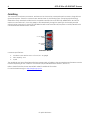
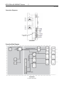
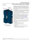
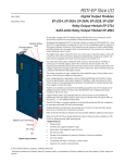
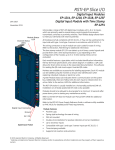
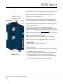
RSTI-EP Slice I/O PROFINET® Scanner EPXPNS001 GFK-2965 November 2015 PWR, SF, BF, MT, LINK 1, ACT 1, LINK 2, and ACT 2 LEDs Ethernet Ports Power Supply LED The EPXPNS001 PROFINET Scanner is a PROFINET I/O device certified by the PROFINET user organization. The network adapter is the head module for the RSTi-EP system bus, to which up to 64 active RSTi-EP modules can be connected. The PROFINET network adapter has two Ethernet ports, and an integrated switch. The PROFINET Scanner can be accessed with a system-independent web server application via the USB service interface or the Ethernet. Thus, all information, such as diagnostics, status values and parameters, can be read and all connected modules can be simulated or forced. The station's main power supply is integrated in the PROFINET Scanner. Power is supplied via two 4-pole connectors, separated into the input and output current paths. Caution, the RSTi-EP station is usually installed on a horizontally positioned DIN rail. Installation on vertically positioned DIN rails is also possible. However, the heat dissipation is reduced such that the derating values change (refer to the section, Thermal Derating. Modules should to be allowed to de-energize for a minimum 10 seconds after power down, prior to starting any maintenance activity. The PROFINET Scanner cannot be hot-swapped. Refer to the RSTi-EP Slice I/O User Manual (GFK-2958) for additional information. Refer to the RSTi-EP Power Supply Reference Guide, a software utility available on PME V9.00, for detailed power-feed requirements. Module Features Door for Micro USB Port PROFINET Scanner Supports up to 64 active RSTi-EP modules Spring-style technology for ease of wiring DIN rail mounted Double-click installation for positive indication of correct installation Built-in Web Server for diagnostic information and firmware update through Ethernet and micro USB port Supports Media Redundancy Protocol (MRP) Client mode operation Support for daisy-chain/line, star, or ring (MRP) technologies Two switched Ethernet ports; 8-conductor RJ-45 shielded twisted pair 10/100 Mbps copper interfaces Fast start-up < 500 ms with a maximum of 10 modules © 2015 General Electric Company. All Rights Reserved. Indicates a trademark of General Electric Company and/or its subsidiaries. All other trademarks are the property of their respective owners. * 2 RSTi-EP Slice I/O PROFINET Scanner GFK-2965 Ordering Information Module Description EPXPNS001 RSTi-EP Slice I/O PROFINET IRT Network Adapter Specifications EPXPNS001 System data Connection Fieldbus protocol Process image Number of modules Configuration interface Transfer rate Data format PROFINET I/O Update Rate Supports MRP Supply Supply voltage for system and inputs Supply voltage for outputs Max. feed-in current for input modules Max. feed-in current for output modules Current consumption from system current path ISYS Connection data Type of connection Conductor cross-section General data Operating temperature Storage temperature Air humidity (operation/transport) Width Depth Height Weight Configuration 2 x RJ-45 PROFINET Version 2.3 Class C I/O Device (IRT, RT) Input data width max. 512 bytes Output data width max. 512 bytes Parameter data max. 4362 bytes Diagnostic data max. 1408 bytes max. 64 active Micro USB 2.0 Fieldbus Max. 100 Mbps RTSi-EP system bus Max. 48 Mbps Default: Motorola Configurable: Intel Configurable selections: 1ms, 2ms, 4ms, 8ms, 16ms, 32ms, 64ms, 128ms, 256ms and 512ms Yes 20.4V – 28.8V 20.4V – 28.8V 10 A 10 A 116 mA Spring style Single-wired, fine-wired 0.14 – 1.5 mm2 (AWG 26 – 16) -20°C to +60°C (-4 °F to +140 °F) -40°C to +85°C (-40 °F to +185 °F) 5% to 95%, noncondensing as per DIN EN 61131-2 52 mm (2.05 in) 76 mm (2.99 in) 120 mm (4.72 in) 220 g (7.76 oz) V2.3 GSDML file is available on the Support website http://support.ge-ip.com for download and import into Proficy Machine Edition. The GSDML supporting a firmware release is part of the firmware upgrade kit available on the Support website. For public disclosure RSTi-EP Slice I/O PROFINET Scanner 3 GFK-2965 LEDs LED Status Indicators LED PWR Indication Power LED SF System fault BF Bus fault MT Maintenance Required LINK 1 Connection ACT 1 Active LINK 2 Connection ACT 2 Active LED State/Description Green: Supply voltage connected Red: Configuration error, or error in the PROFINET Scanner, or error in a module, or there is a new diagnostic report Red flashing: Station in Force mode Red: No connection to the fieldbus Red flashing: Configuration error, no connection to the control unit, or error in the parameter set Yellow: Error on the system bus or fieldbus Green: Connection established between port 1 of the PROFINET Scanner and another field device Yellow flashing: Data being exchanged on port 1 Green: Connection established between port 2 of the PROFINET Scanner and another field device Yellow flashing: Data being exchanged on port 2 LED Indicators LED Power Supply EPXPNS001 Green: Supply voltage > 18 V DC Red: At least one current path < 18 V 3.1 Green: Input current path supply voltage > 18 V DC 3.2 Red: Input current path supply voltage < 18 V DC 3.3 3.4 Red: Internal fuse defective 4.1 4.2 4.3 4.4 Green: Output current path supply voltage > 18 V DC Red: Output current path supply voltage < 18 V DC Red: Internal fuse defective For public disclosure 4 RSTi-EP Slice I/O PROFINET Scanner GFK-2965 Field Wiring The connection frame has one connector, and two 24 V DC wires can be connected to each connector, along with two ground connections. Those four connectors are used as shown in the following figure. The Spring style technology allows either finely stranded or solid wire with crimped wire-end ferrules or ultrasonically welded wires, each with a maximum cross-section of 1.5 mm² (16 guage), to be inserted easily through the opening in the clamping terminal without having to use tools. To insert fine stranded wires without wire-end ferrules, the pusher must be pressed in with a screwdriver and released to latch the wire. 24 V DC GND Connector Block Connector Specifications: • conductor cross-section 0.14 to 1.5 mm² (26 – 16 guage) • max. ampacity: 10 A • 4-pole The modules do not have a fused sensor/activator power supply. All cables to the connected sensors/actuators must be fused corresponding to their conductor cross-sections (as per Standard DIN EN 60204-1, section 12). Refer to the RSTi-EP Slice I/O User Manual (GFK-2958) for additional information. For technical assistance, go to http://support.ge-ip.com. For public disclosure RSTi-EP Slice I/O PROFINET Scanner 5 GFK-2965 Connection Diagrams Door for Micro USB Port EPXPNS001 Connection Block Diagrams EPXPNS001 EPXPNS001 For public disclosure 6 RSTi-EP Slice I/O PROFINET Scanner GFK-2965 Installation in Hazardous Areas EQUIPMENT LABELED WITH REFERENCE TO CLASS I, GROUPS A, B, C & D, DIV. 2 HAZARDOUS AREAS IS SUITABLE FOR USE IN CLASS I, DIVISION 2, GROUPS A, B, C, D OR NON-HAZARDOUS AREAS ONLY WARNING - EXPLOSION HAZARD - SUBSTITUTION OF COMPONENTS MAY IMPAIR SUITABILITY FOR CLASS I, DIVISION 2; WARNING - EXPLOSION HAZARD - WHEN IN HAZARDOUS AREAS, TURN OFF POWER BEFORE REPLACING OR WIRING MODULES; AND WARNING - EXPLOSION HAZARD - DO NOT CONNECT OR DISCONNECT EQUIPMENT UNLESS POWER HAS BEEN SWITCHED OFF OR THE AREA IS KNOWN TO BE NONHAZARDOUS. ATEX Marking II 3 G Ex nA IIC T4 Gc Ta: -20°C to +60°C (-4° F to +140 °F) Thermal Derating The power supply is restricted according to the temperature. The following values apply for the horizontal and vertical positioning of the RSTi-EP station: Temperature-dependent Values for the Power Supply Network adapter power supply Power-feed module power supply Horizontal Vertical 60°C (140 °F) : 2 x 8 A 55°C (131 °F) : 2 x 6 A 55°C (131 °F) : 2 x 10 A 50°C (122 °F) : 2 x 8 A 60°C (140 °F) : 1 x 10 A 55°C (131 °F) : 1 x 8 A Refer to the RSTi-EP Slice I/O Module User Manual (GFK-2958) for additional information. Supported Modules and Power Supplies The following modules can be used with this release of the RSTi-EP PROFINET Network Adaptor : Catalog Number Module Description Digital Input Modules EP-1214 Digital Input, 4 Points, Positive Logic 24VDC, 2,3, or 4 Wire EP-1218 Digital Input, 8 Points, Positive Logic, 24VDC 2 Wire EP-1318 Digital Input, 8 Points, Positive Logic, 24VDC 3 Wire EP-125F Digital Input, 16 Points, Positive Logic, 24VDC, 1 Wire EP-12F4 Digital Input, 4 Points, Positive Logic 24VDC, 2,3, or 4 Wire, Time stamp Digital Output Modules EP-2214 Digital Output, 4 Points, Positive Logic 24VDC, 0.5A, 2,3, or 4 Wire EP-2614 Digital Output, 4 Points, Positive Logic 24VDC, 2.0A, 2,3, or 4 Wire EP-2634 Digital Output, 4 Points, Positive/Negative Logic 24VDC, 2.0A, 2,3, or 4 Wire EP-2218 Digital Output, 8 Points, Positive Logic, 24VDC, 0.5A, 2 Wire EP-225F Digital Input, 16 Points, Positive Logic, 24VDC, 0.5A, 1 Wire EP-2714 Digital Relay Output, 4 Points, Positive Logic, 24 - 220 VDC/VAC, 6A, 2 Wire EP-2814 Solid-state Relay Output Module Digital Relay Output Modules For public disclosure RSTi-EP Slice I/O PROFINET Scanner 7 GFK-2965 Analog Input Modules EP- 3164 Analog Input, 4 Channels Voltage/Current 16 Bits 2, 3, or 4 Wire EP- 3264 Analog Input, 4 Channels Voltage/Current 16 Bits with Diagnostics 2, 3, or 4 Wire EP- 3124 Analog Input, 4 Channels Voltage/Current 12 Bits 2, 3, or 4 Wire EP-3368 Analog Input, 8 Channels Current 16 Bits 2, 3, or 4 Wire EP-3468 Analog Input, 8 Channels Current 16 Bits 2, 3, or 4 Wire, Channel Diagnostic EP-3704 Analog Input, 4 Channels RTD 16 Bits with Diagnostics 2, 3, or 4 Wire EP-3804 Analog Input, 4 Channels TC 16 Bits with Diagnostics 2, 3, or 4 Wire EP-4164 Analog Output, 4 Channels Voltage/Current 16 Bits 2, 3, or 4 Wire EP-4264 Analog Output, 4 Channels Voltage/Current 16 Bits with Diagnostics 2, 3, or 4 Wire EP-5111 1 Channel High Speed Counter, AB 100 kHz 1 DO 24VDC, 0.5A EP-5112 2 Channel High Speed Counter, AB 100 kHz EP-5212 2 Channel Frequency Measurement, 100 kHz EP-5422 2 Channels PWM Output, Positive Logic, 24VDC, 2.0 A EP-5442 2 Channels PWM Output, Positive Logic, 24VDC, 0.5 A Analog Output Modules Speciality Modules Power Feed Modules for Input Current Path EP-7631 Power Module, 1 Channel 24VDC Input Flow 10A EP-7641 Power Module, 1 Channel 24VDC Output Flow 10A EP-1901 1 Safe Feed-Input, 24 VDC EP-1902 2 Safe Feed-Inputs, 24 VDC, Programmable Delay EP-1922 2 Safe Feed-Inputs, 24 VDC EP-711F Power Module, 16 Channels 24VDC Potential Distribution +24 VDC from Input Current Path EP-751F Power Module, 16 Channels 24VDC Potential Distribution +24 VDC from Output Current Path EP-700F Power Module, 16 Channels 24VDC Potential Distribution Functional Earth EP-710F Power Module, 16 Channels 24VDC Potential Distribution +0VDC from Input Current Path EP-750F Power Module, 16 Channels 24VDC Potential Distribution +0VDC from Output Current Path Power Feed Modules for Output Current Path Safe Feed-input Modules Potential Distribution Modules Release History Catalog Number EPXPNS001 Firmware Version Date 01.00 Nov-2015 Comments Initial Release For public disclosure 8 RSTi-EP Slice I/O PROFINET Scanner GFK-2965 Important Product Information for this Release Updates Initial Release Funcional Compatibility Initial Release Problems Resolved by this Release None – Initial Release New Features and Enhancements None – Initial Release Known Restrictions and Open Issues None Operational Notes None Product Documentation RSTi-EP Slice I/O Module User Manual (GFK-2958) RSTi-EP Slice I/O Functional Safety Module User Manual (GFK-2956) GE Intelligent Platforms 1-800-433-2682 1-434-978-5100 www.ge-ip.com For public disclosure