1
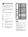
USER MANUAL
l
surroundings can cause greater accumulation of dirt on the unit’s optics
1) Clean with a soft cloth using normal glass cleaning products.
2) Always dry the parts carefully.
3) Clean the Aperture glass at least once every 30 days
The interior of the fixture should be cleaned annually using a vacuum cleaner
or air-jet.
ATTENTION:
USER MANUAL
WS-GB Laser
We strongly recommend internal cleaning to be carried
out by qualified engineer!
SPECIFICATIONS
Mains Input:
AC100~240V, 50/60Hz
Fuse:
250V 1.5A slow blow(20mm glass)
Total Power:
20W
Music Control:
Laser Power:
Internal microphone
50mW Green laser (l=532nm)
300mW Blue laser (l=450nm)
Laser Classification:
3B
Laser Safety Standard:
EN60825-1:2007
Condition Temperature:
10℃~40℃
Measurement:
220mm*180mm*80mm
Net Weight:
1.9kg
This manual contains important laser system safety and operation
information. Read and understand all instructions prior to powering on
laser unit the first time, to avoid laser eye injury and to avoid breaking
Specifications subject to change without prior notice.
The availability of particular products may vary by region. Please check with the dealer.
15
the law. Keep this manual in a safe place for future reference.
USER MANUAL
USER MANUAL
WARNING
Lasers can be hazardous and have unique safety considerations. Permanent
eye injury and blindness is possible if lasers are used incorrectly. Pay close
attention to each safety REMARK and WARNING statement in the user manual.
Read all instructions carefully BEFORE operating this device.
0-10
No output
11-40
Blue
41-80
Green
81-120
Cynn
121-160
Green strobe, blue not strobe
161-200
Blue strobe, Green not strobe
201-255
Blue and Green turn to change
CH4
COLOR
This unit contains high power laser devices internally. Do not open the laser
housing, due to potential exposure to unsafe levels of laser radiation. The laser
power levels accessible if the unit is opened can cause instant blindness, skin
burns and fires.
CH5
0-31
No blanking
BLANKING
32-255
Fast to Slow
0-10
No Strobe
CH6
The manufacturer will not accept liability for any resulting damages caused by the
non-observance of this manual or any unauthorized modification to the device.
11-250
Slow to Fast
251-255
Strobe by sound
STROBE SPEED
CH7
Caution!
Prevent damage or injury from incorrect operation.
Laser!
Laser safety warning labels.
0-255
Slow to Fast
GRATING SPEED
000
Stop
CH8
001-080
Clockwise
081-160
Stop
161-255
Anticlockwise
GRATING
DIRECTION
Recycle
To protect the environment, recycle packing material
wherever possible.
Indoor
The projector is for indoor use only, IP20. Use only in dry
locations. Keep this device away from rain and moisture,
excessive heat, humidity and dust. Do not allow contact with
water or other fluids.
Disposal
Location
Don’t throw this product away just as general trash, please
dispose of this product following the abandon electronic
product regulations in your area.
The projector must be installed in a location with adequate
ventilation, at least 50cm (20 inches) from adjacent surfaces.
Be sure that no ventilation slots are blocked.
MAINTENANCE
l
l
l
l
l
l
1
Make sure the area below the installation place is free from unwanted persons
during servicing
Switch off the fixture, unplug the mains cable and wait until the unit has been
cooled down.
Housings, fixations and installations spots( ceiling, truss, suspensions) should
be totally free from any deformation
The mains cables must be in impeccable condition and should be replaced
immediately when even a small problem is detected
In order to protect the fixture from overheat the cooling fans (if any) and
ventilation openings should be cleaned monthly.
The cleaning of aperture glass and scanner mirrors must be carried out
periodically to optimize light output. Cleaning frequency depends on the
environment in which the fixture operates: damp. smoky or particularly dirty
14
USER MANUAL
USER MANUAL
LASER SAFETY WARNINGS
MASTER/SLAVE MODE
l
Press FUNC to enter MODE OPTION
l
Till to LED panel shows SLAV
l
Press ENTER to confirm the setting.
The laser is working in “SLAVE MODE”. Connect MASTER laser and SLAVE
lasers with DMX cable, the SLAVE lasers do what exactly MASTER laser does.
Check “5.2 DMX connection” to have more details about laser connection.
Potential laser injury hazard exists with this product! Read these
instructions carefully, which includes important information about
installation, safe use and service!
Caution
Avoid direct eye contact with laser light. Never
intentionally expose your eyes or others to direct laser
light..
Caution
This laser product can potentially cause instant eye
injury or blindness if laser light directly strikes the eyes.
Caution
It is illegal and dangerous to shine this laser into
audience areas, where the audience or other personnel
could get direct laser beams or bright reflections into
their eyes.
Caution
It is a US Federal offense to shine any laser at aircraft.
Caution
There are no user serviceable parts inside the unit. Do
not open the housing or attempt any repairs yourself. In
the unlikely event your unit may require service, please
contact the dealer nearest to you.
Caution
Use of controls or adjustments or performance of
procedures other than those specified herein may result
in hazardous radiation exposure.
DMX MODE
l
Press FUNC to enter MODE OPTION
l
Till to LED panel shows D001.
l
Press ENTER to confirm the setting.
The laser is working in “DMX MODE”. With help of UP/DOWN button, it could be
easily change the DMX address of the laser.
1
2
FUNC
UP
3
DOWN ENTER
DMX CHANNEL
CHANNEL
DMX
CONTROL
000-049
BLACKOUT
CH1
050-099
AUTO SHOW
CONTROL MODE
100-149
MUSIC SHOW
to:
150-255
DMX MODE
l
Be qualified
Clockwise (fast to slow)
l
Follow the instructions of this manual
0-115
CH2
116-139
Stop
140-255
Anticlockwise (slow to fast)
MOTOR A SPEED
CH3
0-19
MOTOR B SPEED
20-255
Stop
Every person involved with installation and maintenance of this device has
CAUTION! Be careful with your operations. With a high voltage you
can suffer a dangerous electric shock when touching the
wires!
Slow to Fast
13
2
USER MANUAL
USER MANUAL
LASER SAFETY LABEL REPRODUCTIONS
The laser is working in stand alone. Each time when you turn on your laser, you
will have this confirmed laser show.
1
2
FUNC
CAUTION – CLASS 3B LASER RADIATION,
WHEN OPEN, AVOID EXPOSURE TO
BEAM
THE LASER INDICATEDS THE LASER
BEAM OUTPUT APERTURE.
3
DOWN ENTER
In the MODE OPTION setting, the stand alone laser show that you are going to
choose is flashing. Press UP or DOWN to change stand alone laser show, you will
have 21 different stand alone preprogrammed laser show. Their DISPLAY and
EFFECT are listed below:
DISPALY
LASER RADIOATION AVOID EXPOSURE
TO BEAM CLASS3B LASER PRODUCT.
UP
3
STAND ALONE MODE LASER EFFECT
AUTA
Auto mixed slow laser with random show
MG01
Pattern choose (01-79)
MM 1
Motor speed (1-4 turn to left) (5 stop) (6-9 turn to right)
MC 0
Color choose
MS00
Strobe speed (00-15)
SOUD
Sound activated
D001
DMX control effect
SLAV
Master/Slave control effect
12
USER MANUAL
USER MANUAL
LASER EXPOSURE WARNING
CONTROL&FUNCTION
l
l
l
l
Regular breaks during operation are essential to maximize the life of this
device as it is not designed for continual use.
Do not switch the unit on and off in short time intervals
Always unplug the unit when it is not used for a longer time. Or before
replacing the bulb or start servicing.
In the event of serious operation problems, stop using the fixture and
contact your dealer immediately.
Attention
LASER LIGHT
AVOID DIRECT EYE EXPOSURE
Further guidelines and safety programs for safe use of lasers can be found in the
ANSI Z136.1 Standard “For Safe Use of Lasers”, available from
“www.laserinstitute.org”. Many local governments, corporations, agencies,
military and others, require all lasers to be used under the guidelines of ANSI
Z136.1. Laser Display guidance can be obtained via the International Laser
Display Association, www.laserist.org.
Laser will be output from laser aperture in 5 seconds
after the unit is powered on.
Operating Mode
When laser is powered on, LED monitor on rear panel shows the current
operating standalone mode or DMX address of DMX mode. With help of LED
control panel, it is very easy to set and change the operating mode of laser. After
every resetting and saved, the new mode information will be shown on LED
monitor at next power on.
Mode/Function Option, to choose the operating mode of laser.
Confirmation, to confirm all setting or change of LED control panel.
LASER EMISSION DATA
Laser Classification
Class 3B
Green Laser Medium
DPSS Nd:YVO4, 532nm
Blue Laser Medium
DPSS 450nm
Beam Diameter
<5mm at aperture
Pulse Data
All pulses < 4Hz (>0.25sec)
Divergence (each beam)
<2mrad
Divergence (total light)
<160 degrees
Laser Power
Blue>300mW, Green>50mW
* As measured under IEC measurement conditions for classification.
LASER COMPLIANCE STATEMENT
UP/DOWN, to change operating mode, parameter or DMX address.
According to the EN 60825-1:1994 + A1:2002+A2:2001 + COTT regulations, this
laser fall under the classification 3B.Direct eye exposure can be dangerous.
Stand Alone Preprogram Laser Show
l
Press FUNC to enter MODE OPTION.
l
Press UP or DOWN to select your favorite Stand Alone mode as above.
l
Press ENTER to confirm the setting.
11
4
USER MANUAL
USER MANUAL
BEFORE OPERATION
Rear Panel
Unpacking Instructions
CAUTION! Immediately upon receiving a fixture, carefully unpack the
carton, check the contents to ensure that all parts are present,
and have been received in good condition. Notify the shipper
immediately and retain packing material for inspection if any
parts appear damage from shipping or the package itself
shows signs of mishandling. Save the package and all
packing materials. In the event that a fixture must be returned
to the factory, it is important that the fixture be returned in the
original factory box and packing.
What is included
The carton or flight case contain following items:
NAME
QTY
Laser Light
1pc
Keys (for key switch)
2pcs
NO.
NAME
Power Supply
1pc
3
Power Supply
User Manual
1pc
4
Power Switch
DESCRIPTION
With IEC socket and integrated fuse holder
Switch ON and OFF the fixture
Turn the knob (potentiometer) until the laser
Power Supply
5
Sensitivity Knob
To determine the power requirements for a particular fixture, see the label affixed
to the back plate of the fixture of refer to the fixture’s specifications chart. A
fixture’s listed current rating is its average current draw under normal conditions.
All fixtures must be powered directly off a switched circuit and cannot be run off a
rheostat (variable resistor) or dimmer circuit, even if the rheostat or dimmer
channel is used solely for a 0% to 100% switch. Before applying power to a fixture,
check that the source voltage matches the fixture’s requirement.
The unit is supplied with a power plug appropriate to its voltage and destination.
Should any other connections be required they must be carried out with the
following configuration.
6
Mic Knob
To detect the music/sound signal
7
Safety Eye
Used to attach a safety cable when the fixture
is rigged
5
8
Interlock Switch
9
10
LED Display Board
11
DMX Input
DMX Output
works in sync with the music
To interlock laser diodes output
To display operation menu
3 pins female XLR connector
3 pins male XLR connector
10
USER MANUAL
USER MANUAL
PRODUCT OVERVIEW
l
This device has left out premises in absolutely perfect condition. In order to
maintain this condition and to ensure a safe operation, it is necessary for the
user to follow the safety instructions and warning notes written in this
manual.
l
The manufacturer will not accept liability for any resulting damages caused
by the non-observance of this manual or any unauthorized modification to
the device.
Cable(EU)
Cable(US)
Pin
International
Brown
Black
Live
L
Light blue
White
Neutral
N
Yellow/Green
Green
Earth
Front Panel
DMX-512 connection between fixtures
The fixture is equipped with 3-pin XLR sockets for DMX input and output. The
sockets are wired in parallel. Only use a shielded twisted-pair cable designed for
3-pin XLR-plugs and connectors in order to connect the controller with the fixture
or one fixture with another.
Occupation of the XLR-connection
Caution:
NO.
NAME
1
Laser Aperture
At the laser fixture, the DMX-cable has to be terminated with
a terminator. Solder a 120 Ohm resistor between Signal (-)
and Signal (+) into a 3-pin XLR-plug and plug and plug it in
the DMX-output of the last fixture.
DESCRIPTION
Laser effect output aperture
9
6
USER MANUAL
USER MANUAL
Building a serial DMX-chain
Rigging the Fixture
CAUTION:
l
Please consider the respective national norms during
the installation! The installation must only be carried out
by an authorized employee or dealers!
The installation of the fixture has to be built and constructed in a way that it
can hold 10 times the weight for 1 hour without any harming deformation.
l
The installation must always be secured with a secondary safety attachment,
e.g. an appropriate catch net. This secondary safety attachment must be
constructed in a way that no part of the installation can fall down if the main
attachment fails.
l
l
l
l
l
l
l
l
If you are using the standard DMX-controllers, you can connect the
DMX-output of the controller directly with the DMX-input of the first fixture in
the DMX-chain. If you wish to connect DMX-controllers with other
XLR-outputs, you need to use adapter cables.
Connect the DMX-output of the first fixture in the DMX-chain with the
DMX-input of the next fixture. Always connect output with the input of the
next fixture until all fixtures are connected.
If you use a controller with 5 pins DMX connector, you need to use a 5 to 3
pins adaptor.
At last fixture, the DMX cable has to be terminated with a terminator. Solder
a 120 Ohm 1/4W resistor between pin 2(DMX-) and pin 3(DMX+) into a 3
pins XLR-plug and plug it in the DMX-output of the last fixture.
Connect the fixture together in a daisy chain by XLR plug cable from the
output of the fixture to the input of the next fixture. The cable cannot be
branched or split to a Y cable. DMX 512 is a very high speed signal.
Inadequate or damaged cables, soldered joints or corroded connectors can
easily distort the signal and shut down the system.
The DMX output and input connectors are pass-through to maintain the
DMX circuit, when power is disconnected to the unit.
Each fixture needs to have a DMX address to receive the data from the
controller. The DMX address number which could be read from rear panel of
each fixture is between 000~511.
The end of the DMX 512 chain should be terminated to reduce signal errors.
7
l
Make sure the area below the installation place is free from unwanted
persons during rigging, de-rigging and servicing.
l
The operator has to make sure that safety-relating and machine-technical
installations are approved by an expert before taking into operation for the
first time and after changes before taking into operation another time.
l
The operator has to make sure that safety-relating and machine-technical
installations are approved by a skilled person once a year.
l
The fixture should be installed in the position where persons cannot reach
and where persons may walk by or be seated.
CAUTION:
When installing the device, make sure there is no highly
in inflammable material (decoration articles, etc.) in
between a distance of min o.5 meter.
8