1
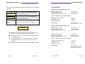
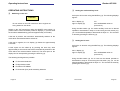
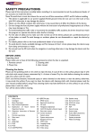
OPERATING INSTRUCTIONS
VHF Transceiver AR 3209
BECKER FLUGFUNKWERK GMBH
Baden Airpark
D-77836 Rheinmünster (Germany)
Tel.:
+49 (0) 7229 / 305-0
Fax:
+49 (0) 7229 / 305-217
Subject to technical changes
© Copyright bei Becker Flugfunkwerk
Issue 10/95
Article-No. 891.436-071
Operating Instructions
Becker Flugfunkwerk GmbH
Baden Airpark, Gebäude B 108
77836 Rheinmünster (Germany)
Becker AR 3209
Fault description
TABLE OF CONTENTS
IMPORTANT
1
INTRODUCTION
1
Unit type :
Serial number :
Aircraft type :
Brief description of the fault :
.................................................................................................................
.................................................................................................................
.................................................................................................................
.................................................................................................................
SAFETY INFORMATION
3
GENERAL INFORMATION
5
CONTROLS AND INDICATORS
6
OPERATING INSTRUCTIONS
8
p
Switching on the unit
8
Should the fault only occur sporadically, please answer the following
questions :
p
Transmit/receive mode
9
p
Operation of intercom mode
10
p
p
p
p
p
p
p
Audio auxiliary input
Jamming of transmit button
Operation of the various modes
Modes
Mode 1
Mode 2
Mode 3 (Displays of fixed frequencies
in the various channels)
Service mode (equipment configurations)
Calling up the service mode
Setting the squelch threshold
Setting the sidetone level
Setting the audio auxiliary level
Setting the IC level
Release the frequency setting (channel selection only)
Release the frequency storage
11
11
12
12
13
15
16
Tel.
+49 (0) 7229 / 305-0
Fax
+49 (0) 7229 / 305-217
The fault occurs after . . . . . minutes of operation.
The fault occurs under the following environmental conditions :
p
low temperature
p
high temperature
p
high humidity
p
vibration
The fault is engine speed-dependent and occurs above/below . . . . . . . . rpm.
Should any problems arise, I may be contacted under the following adress :
.................................................................. I am available between 8 a.m.
.................................................................. and 4 p.m. under the following
.................................................................. telephone number :
.............................................................. office: ..................................
................................................................private : ...................................
Page 32
Issue 10/95
p
p
p
p
p
p
p
p
Issue 10/95
17
19
20
20
21
21
22
22
Page 1
Operating Instructions
Becker AR 3209
p
Erase stored frequencies
23
p
Entry of password to interlock the equipment
configuration
23
p
Setting the dynamic mike input sensitivity
24
p
Inhibiting the transmit mode for one or more
memory channel
25
p
Squelch fast mode
25
p
Indication the software version and change status
26
p
Ending of the service mode
26
TECHNICAL DATA
27
p
28
REPAIR INSTRUCTIONS
If an equipment fault the unit may be sent to a Becker Dealer or the
Becker customer service together with a description of the fault. The
completed fault description shortens the repair times and hence lowers
the resultant costs.
These operating instructions do not replace the equipment manuals
listed below.
r
General data AR 3209 - (09) / AR 3209 - (11)
REPAIR INSTRUCTIONS
29
p
29
Equipment manuals
Page 2
Issue 10/95
Equipment manuals
to be purchased from the manufacturer or Becker Dealer :
Installation and Operation DV 37501.03, Article No.: 892.531-071
Maintenance and Repair DV 37501.04, Article No.: 892.548-071
Issue 10/95
Page 31
Operating Instructions
r
Becker AR 3209
IMPORTANT
General data AR 3209 - (09) / AR 3209 - (11)
Frequency range
118.000 MHz to
136.975 MHz
Number of channels
760
Channel spacing
25 kHz
Operating temperature range
- 20° C to + 55° C
Dimensions
Carefully read these operating instructions right through before
attempting to operate the VHF transceiver.
Keep these operating instructions carefully. They contain important
safety and operating instructions for the VHF transceiver.
INTRODUCTION
146 mm x 47.5 mm
194 mm
Thank you for purchasing the BECKER VHF transceiver. The
VHF transceiver can be installed in the instrument panel or centre
console or operating console and is easy to operate. The technology
used is to the state of the art.
- AR 3209 - (09)
- AR 3209 - (11)
1 kg
1.2 kg
Fuse internal
5A
To fully utilise the capabilities of your VHF transceiver, please carefully
read these operating instructions right through before you start
operating the set.
Front panel
Depth of unit without cable connector
Weight
If you have any questions regarding the operation of the VHF
transceiver, please get in touch with your nearest Becker Dealer or with
the Becker Customer Service.with your nearest Becker Dealer or with
the Becker Customer Service.
Page 30
Issue 10/95
Issue 10/95
Page 3
Operating Instructions
Becker AR 3209
The CAUTION, WARNING and NOTE highlights have the following
meanings :
WARNING
Failure to comply, or incorrect compliance,
with these instructions or procedures can lead
to injuries or fatal accidents.
CAUTION
Failure to comply, or incorrect compliance,
with these instructions or procedures can lead
to damage to equipment.
NOTE
Feature to which attention should be drawn.
Technical Data
Power supply voltage AR 3209 - (09)
Nominal supply voltage
Supply voltage range
Emergency operation (10.0 V)
13.75 V DC
12.4 V to 15.1 V
Good intercom
Power consumption without panel lighting
“Standby” reception mode
Reception mode
Transmission mode
£ 70 mA
£ 500 mA
£ 2.5 A
Panel lighting
1 A at 5 V DC
400 mA at 13.75 V DC
Power supply voltage AR 3209 - (11)
Nominal supply voltage
Supply voltage range
Emergency operation (10.0 V)
CAUTION
l
Never connect the VHF transceiver to alternating current
voltage or to voltage sources exceeding 32 V DC.
l
Never connect the VHF transceiver with reversed polarity
to a voltage source.
l
The installation or use of the VHF transceiver in ambient
temperatures below -20° C or above +55° C is to be
avoided.
l
Page 4
Switch off the unit when starting or shutting down engines.
Issue 10/95
13.75 V DC
12.4 V to 15.1 V
Good intercom
or
Nominal supply voltage
Supply voltage range
Emergency operation (20.0 V)
27.5 V DC
24.8 V to 30.3 V
Good intercom
Power consumption without panel lighting
“Standby” reception mode
Reception mode
Transmission mode
£ 70 mA
£ 500 mA
£ 2.5 A
Panel lighting
1 A at 5 V DC
400 mA at 13.75 V DC
200 mA at 27.5 V DC
Issue 10/95
Page 29
Operating Instructions
r
Becker AR 3209
SAFETY INFORMATION
Speaker muting switch ON/OFF
l
A speech test is to be performed before startup and it
should be noted that if the speech test is carried out close
to the ground station the results may be positive even if
the antenna cable is broken or short-circuited. At a
distance of 5 to 10 km no connection will be made.
l
Use a loud voice for speech communication and hold the
microphone close to the lips. Otherwise cabin noise can
be intrusive and make understanding difficult.
l
Use only microphones or headsets which are suitable for
use in aircraft. In aircraft made of wood or synthetic
materials or in gliders or helicopters, incoming radiation on
the equipment antenna can affect the integrated amplifier
of the microphone (feedback). This is noticeable in the
ground station by whistling and/or heavy distortion. The
described disturbances can occur in different ways on the
different transmission channels.
l
Transmit buttons can stick and cause continuous
transmission. Therefore, when transmitting ensure that the
green LED disappears when the transmission button is
released.
Call up function SF 12 using the MDE key. The following displays
appears :
Top line
Bottom line
OFF =
On =
SF12
OFF or On
Speaker muting on
Speaker always switched on
Select the function using the kHz switch. Store the required function by
pressing the STO key. This selection becomes active after ending the
service mode.
r
Indication the software version and change status
Call up function SF 13 using the MDE key (4). The following displays
appear :
left LC display (7)
right LC display (8)
r
Software version and change status :
Microprocessor
Software version and change status :
CO-Miroprocessor (PIC)
Ending of the service mode
The VHF transceiver must be switched off to end the service mode.
Page 28
Issue 10/95
Issue 10/95
Page 5
Operating Instructions
Becker AR 3209
r
Inhibiting the transmit mode for one or more
memory channel
Call up function SF 10 using the MDE key (4). The following displays
appear :
left LC display (7)
right LC display (8)
SF 10
CH channel number
Using the kHz (10) (steps of 1) or MHz (9) (steps of 10) switch, select
the desired channel for inhibiting the transmit mode. Store the channel
by pressing the STO key (3). Several channels can be selected on
priority channels. When the STO key (3) is pressed again, the inhibiting
transmit mode is canceled.
r
Blank
FSqL
no function
Page 6
Issue 10/95
Issue 10/95
Page 27
Operating Instructions
Becker AR 3209
Set any 4-digit numerical code using the kHz (10) (steps of 1) or MHz
(9) (steps of 10) switch. Store the numerical code by pressing the STO
key (3).
NOTE
As soon as a password is given a 0 appears in the bottom
line when the service mode is called up. The numerical
code must then be input using the MHz (9) or kHz switch
(10) and press the STO key. If the VHF transceiver
detects a false numerical code, it automatically switches
to the last mode. If the password is to be erased or
changed, this is done by calling up the service mode using
the old password. The SF 15 function is then chosen and
either a 0 is entered everywhere or the changed
numerical code is entered.
r
GENERAL INFORMATION
The VHF transceiver AR 3209 enables voice communication on
760 channels in the 118.000 MHz to 136.975 MHz range with a channel
spacing of 25 kHz. It complies with the requirements of ICAO Annex 10
valid from 01.01.1995.
The VHF transceiver is designed with sufficient mechanical strength to
enable it to be fitted in an aircraft without any limitations. There is no
restriction within the verified environmental classes on fitting in the
instrument panel or centre console or operating console, or fixed
mounting in the fuselage, of all types of aircraft including helicopter.
Setting the dynamic mike input sensitivity
Call up function SF 9 using the MDE key (4). The following displays
appear :
left LC display (7)
right LC display (8)
SF 9
00 bis 63
Standard value 32
(LO sensitivity HI)
The dynamic mike input sensitivity can be changed upwards or
downwards using using the kHz (10) (steps of 1) or MHz (9) (steps of
10) switch. The set value is stored by pressing the STO key (3).
Page 26
Issue 10/95
Issue 10/95
Page 7
Operating Instructions
Becker AR 3209
CONTROLS AND INDICATORS
7
5
6
8
OFF = The storage of frequencies in the individual channels is
not possible. The VHF transceiver can only work on
the
set frequency.
ON =
Storage of frequencies in the individual channels is
possible (standard setting)
r
Erase stored frequencies
Call up function SF 7 using the MDE key (4). The following displays
appear :
left LC display (7)
right LC display (8)
1
2
3
4
9
10
Function of controls and indicators
1
ON/OFF rotary switch
SF 7
CH channel number
Select the channel to be erased using the kHz (10) (steps of 1) or MHz
(9) (steps of 10) switch. The stored frequency is erased by pressing the
STO key (3). The channel No. 1 cannot erased.
r
Entry of password to interlock the equipment configuration
Adjustment of volume.
2
Squelch key
Switching the squelch on or off.
Call up the COdE function using the MDE key (4). The following
displays appear :
3
Store key
Storage of set frequency or other
settings.
left LC display (7)
right LC display (8)
4
Function key
Selection of mode.
Page 8
Issue 10/95
Issue 10/95
COdE
0
Page 25
Operating Instructions
r
Becker AR 3209
Release the frequency setting (channel selection only)
5
Exchange key
Mode 2:
Exchange of preset frequency and
active frequency.
6
LE diode, green
Transmit indication (PTT button pressed).
7
LC display
Indication of active transmission/
reception frequency (active frequency).
8
LC display
Indication of preset transmission/
reception frequency (preset frequency).
Call up function SF 5 using the MDE key (4). The following displays
appear :
left LC display (7)
right LC display (8)
SF 5
ON or OFF
Select the required function using the kHz switch (10) and store the
function by pressing the STO key (3).
OFF = Frequency setting not possible.
The VHF transceiver can only work on the frequencies
stored in the individual channels.
ON =
Frequency setting possible (standard setting).
r
CH indication steady :
Indicates the storage channel.
CH indication flashes :
If the initiated storage operation is
not completed by pressing the store
key.
Release the frequency storage
Call up function SF 6 using the MDE key (4). The following displays
appear :
left LC display (7)
right LC display (8)
SF 6
ON or OFF
Select the required function using the kHz switch (10) and store the
selection by pressing the STO key (3).
Page 24
Issue 10/95
9
Frequency selector
switch
Switching the indicated switch
frequency in 1 MHz steps or the
storage channel upwards or
downwards in steps of 10.
10
Frequency selector
switch
Switches the indicated switch
frequency in 25 kHz steps or the
storage channel by 1 step in each
case upwards or downwards, without
carry over.
Issue 10/95
Page 9
Operating Instructions
Becker AR 3209
OPERATING INSTRUCTIONS
r
r
Setting the audio auxiliary level
Switching on the unit
Call up the AU function using the MDE key (4). The following displays
appear :
CAUTION
Do not switch on the VHF transceiver when engines are
being started or shut down.
Switch on the VHF transceiver using the ON/OFF rotary switch (1)
(rotate volume control clockwise). Both LC displays (7, 8) must show
the numbers 188.88 flashing (unit test approximately 2 seconds).
left LC display (7)
right LC display (8)
AU
00 to 63 Standard value 63
(LO level HI)
Using the MHz switch (9) the audio auxiliary level can be altered
upwards or downwards in steps of 10 and using the kHz switch (10),
you can be altered upwards or downwards in steps of 1. The set value
is stored by pressing the STO key (3).
If the test is positive, the transceiver automatically switches to the
mode which was selected before switch-off.
r
If the test is negative, the LC display (7) flashes for approximately
5 seconds.
A fault report can be called up by pressing the store key. After
approximately 5 seconds the transceiver automatically switches to the
mode which was selected before switch-off. The fault report in the
display can be interrupted by pressing the STO key (3).
Setting the IC level
Call up the IC function using the MDE key (4). The following displays
appear :
left LC display (7)
right LC display (8)
IC
00 to 63 Standard value 32
(LO level HI)
The following fault signals are possible :
Using the MHz switch (9) the IC level can be altered upwards or
downwards in steps of 10 and using the kHz switch (10), you can be
altered upwards or downwards in steps of 1. The set value is stored by
pressing the STO key (3).
l
E1 Processor defective
l
E2 Synthesizer failed
l
E3 Fault in EE-PROM
l
E4 Controller (PIC) audio assembly defective
Page 10
Issue 10/95
Issue 10/95
Page 23
Operating Instructions
r
Becker AR 3209
Setting the squelch threshold
If function SqL is called up, the following displays appear :
left LC display (7)
right LC display (8)
sensitivity
SqL
00 to 200
(HI < -> LO)
Standard value 100
Using the MHz switch (9) the squelch threshold can be altered
upwards or downwards in steps of 10 and using the kHz switch (10),
you can be altered upwards or downwards in steps of 5. The set value
is stored by pressing the STO key (3).
r
Setting the sidetone level
Call up the SIdE function using the MDE key (4). The following displays
appear :
left LC display (7)
right LC display (8)
SF 2
00 to 63 Standard value 32
(LO level HI)
Using the MHz switch (9) the sidetone level can be altered upwards or
downwards in steps of 10 and using the kHz switch (10), you can be
altered upwards or downwards in steps of 1. The set value is stored by
pressing the STO key (3).
Page 22
Issue 10/95
The various modes are comprehensively described, toghether with the
setting of the equipment configuration in the service mode, in the
Annex to the General Operating Instructions.
r
Transmit/receive mode
Set the frequency of the local ground station in the preset display and
press the exchange key (5). Rotate the VOL control (1) to the centre
position.
NOTE
If the error message E2 appears in the left indication
during operation, the synthesizer is not latching and
further R/T operation is no longer possible. The VHF
transceiver must be checked in the next service station.
Operate the transmit button and call the ground station. Hold the
microphone close to the lips for optimum speech transmission.
NOTES
The green LED (6) indicates transmit mode. During
transmission a protective circuit prevents a frequency
change or frequency channel change even if the
frequency selector switch (9, 10) is rotated. The keying
functions on the control panel are also inhibited.
Where there is acoustic feedback during transmission the
side tone volume on the VHF transceiver must be turned
down (refer to Service Mode for adjustment).
Issue 10/95
Page 11
Operating Instructions
Becker AR 3209
Set the correct reception volume using the VOL control (1) whilst the
ground station is answering.
Switch on the squelch (2) (press SQL key again). Weak reception
signals and reception noises are suppressed. The switch-on threshold
of the squelch can be set in the service mode.
r
Calling up the service mode
Switch off the VHF transceiver. Hold the MDE key (4) pressed and at
the same time switch on the unit. The VHF transceiver switches to the
service mode without a unit test. SqL appears in the left LC display (7)
and the switch on threshold of the squelch is shown on the right LC
display (8).
NOTES
NOTES
When changing the mode or the frequencies
(PRESET-ACTIVE
frequency)
the
change
is
automatically stored 2 seconds after the last change took
place. Due to this delay changes which were made
immediately before switching off the transceiver will not
be memorized. Exception: Memory actions are stored by
pressing the STO key (3).
r
l
The settings SqL to Spec. no.: are selected in steps by
briefly pressing the MDE key (4) in the service mode. If
the MDE key (4) is pressed at the end of the setting Spec.
no.:, the setting SqL then appears. If a direct return to the
SqL setting is required the MDE key (4) must be pressed
for at least one second.
l
In the service mode the VHF transceiver operates
independently of the settings on the control panel, on the
frequency which was last set as the active frequency.
l
The user can interlock his equipment configuration
settings with the aid of a password. The VHF transceiver
is delivered from the factory without a password. Section
COdE “Entry of password for interlocking the equipment
configuration” describes how to enter a password.
Operation of intercom mode
Switch on the IC switch (external). Operate the intercommunication
(IC). If necessary, the IC volume can be adjusted to the noise level of
the aircraft (for adjustment refer to service mode).
Page 12
Issue 10/95
Issue 10/95
Page 21
Operating Instructions
Becker AR 3209
r
SF7
Erasure of stored frequencies
COdE
Entering a password to interlock the equipment
configuration
Dynamic mike input sensitivity
Inhibiting the transmit mode for one or more memory
channel
no function
Speaker muting switch ON/OFF
Indication the software version and change status
SF9
SF10
FSqL
SF 12
—.—
Audio auxiliary input
A second and third radio unit (navigational receiver) can be monitored
simultaneously via the Audio auxiliary input. During transmission the
auxiliary input is switched off from the Audio end amplifier. If
necessary, the input sensitivity can be matched to the noise level of the
aircraft (for setting refer to service mode).
r
Jamming of transmit button
NOTE
The standard values for the equipment configuration SqL, SIdE, AU, IC
and SF9 are stored in the EE-PROM. If reversion to the standard
values is required, the portable VHF transceiver must be switched off
and switched on again by simultaneously pressing the STO (3) and
MDE (4) keys.
The VHF transceiver is fitted with a protective circuit to protect against
jamming of the transmit button or a short circuit on the key supply line.
For continuous transmissions exceeding two minutes the protective
circuit automatically switches from transmission to reception. This
avoids the switched channel being blocked.
It is possible to activate the transmitter again immediately by
re-pressing the transmit button. In the event of a fault, this is only
possible after the short circuit has been cleared or the transmit button
released.
CAUTION
In Stock to be able to continue transmitting even with the transmit
button jammed, the VHF Transceiver must be switched off and then
back on again. After that the VHF transceiver then continues to operate
in the transmit mode for a further two minutes.
Page 20
Issue 10/95
Issue 10/95
Page 13
Operating Instructions
Becker AR 3209
Operation of the various modes
The VHF transceiver performs various functions which are covered by
individual operating modes. The mode is selected by briefly pressing
the MDE key (4).
r
1
2
3
4
Modes
In mode 3 (channel selection mode) the actuelly memoried frequency
in the left display (7) becomes active frequency
Note
It is not possible to erease memory channel 1, channel 1
only can be over-written.
Leaving the mode
Indication of active frequency in the left LC display (7).
The right LC display (8) is switched off.
The active frequency can be directly changed using the frequency selector switches (9, 10). Frequencies can also be
stored in the individual storage channels.
Indication of active and preset frequencies.
The preset frequency can be set using the frequency selector
switches (9, 10). When the exchange key (5) is pressed the
active and preset frequencies are interchanged.
Further activation of the key reverses the frequency change.
Frequencies can also be stored in the individual storage
channels.
Press the MDE key (4) to leave the mode 3.
r
Service mode (equipment configurations)
Note
The service mode is meant to enable the ground
technicians to set the equipment configuration and must
not be used in flight.
The following settings can be changed or set :
SqL
Setting the switch-on threshold of the squelch
SIdE
Setting the sidetone volume
Display of the storage frequencies in the storage channels and
storing frequencies in the storage channels.
AU
Setting the audio auxiliary volume
IC
Setting the IC volume
Service mode, for setting the equipment configuration.
SF5
Inhibiting the frequency setting
(channel selection only) (ON/OFF)
SF6
Inhibiting the frequency storage (ON/OFF)
Page 14
Issue 10/95
Issue 10/95
Page 19
Operating Instructions
r
Becker AR 3209
Mode 3 (Displays of fixed frequencies in the various
channels)
NOTE
When changing the mode or the frequencies
(PRESET-ACTIVE
frequency)
the
change
is
automatically stored 2 seconds after the last change took
place. Due to this delay changes which were made
immediately before switching off the transceiver will not
be memorized. Exception: Memory actions are stored by
pressing the STO key (3).
Channel selection mode
Select the mode using the MDE key (4). The last indicated storage
channel appears in the right LC display (8) and the stored frequency in
the left LC display (7). The VHF transceiver is ready to transmit and
receive on this frequency.
r
Mode 1
Standard mode
Select the required channel using the kHz frequency selector switch
(10) (steps of 1) or MHz frequency selector switch (9) (steps of 10).
The left LC display (7) indicateds the active frequency. The right LC
display (8) is switched off.
NOTE
The VHF transceiver is always ready to transmit and
receive on the frequency shown in the left “ACTIVE”
display.
The active frequency can be changed with the MHz and kHz frequency
selector switches (9, 10).
Storage process
Pressing the STO key (3) activates a storage process as described in
Mode 1 (with a slight change).
In Modes 1 and 2 the frequency shown in the left LC display (7) remains
active regardless of the storage process.
Page 18
Issue 10/95
Storage operation
Press STO key (3). The active frequency remains displayed in the left
LC display (7), the VHF transceiver is ready to transmit and receive on
this frequency. The active frequency appears flashing in the right LC
display (8).
Issue 10/95
Page 15
Operating Instructions
Becker AR 3209
The required frequency can be set using the kHz frequency selector
switch (10) and MHz frequency selector switch (9).
Press STO key (3). The next free channel is shown flashing “ch”. Press
the STO key (3). The selected frequency is stored in the free speaker
channel and the storage process is ended.
A no memory channel is free, the highest assign memory channel is
selected automatically or select the channel to be overwritten using the
kHz frequency selector switch (10) and press the STO key (3). This
means that this channel will be overwritten with the new frequency and
the storage process ended.
NOTE
If no input takes place within approximately seven
seconds, the VHF transceiver switches to the previously
set mode.
r
Mode 2
Select mode 2 using the MDE key (4). The last indicated active and
preset frequencies in each case are displayed in the right (8) and left
(7) LC displays.
The preset frequency (right LC display (8)) is set using the MHz and
kHz frequency selector switches (9, 10).
Press the Exchange key (5) to effect an exchange from the active to the
preset frequency. Further activation of the key reverses the frequency
change.
Leaving the mode
To leave the mode, press the MDE key (4).
Storage process
Pressing the STO key (3) activates a storage operation as described in
Mode 1. The preset frequency appears flashing in the right hand LCD.
Leaving the mode
Press the MDE key (4) to leave the mode.
Page 16
Issue 10/95
Issue 10/95
Page 17