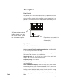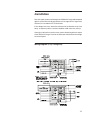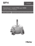
1
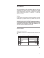
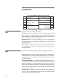
/ Marley 440 and 450 Vibration Switch /
User Manual 07-1273
Contents
Section 1 - General Description.............................................................. 3
Section 2 - Mechanical Installation......................................................... 8
Section 3 - Electrical Wiring.................................................................... 9
Section 4 - Control Settings.................................................................. 13
Section 5 - System Block Diagram....................................................... 14
Wiring Diagram...................................................................................... 15
Description
Introduction
The single set point model contains one trip limit for shutdown. The optional
dual set point model contains two independent trip limits; one for alarm and
one for shutdown. Shutdown and Alarm trip is set in velocity. In addition,
a 4-20 mA output proportional to vibration level is provided.
The 440 and 450 performance, wiring, and specifications are identical except for the enclosure. The 440 meets NEMA 3, 4 and 12. The 450 meets
these and certain explosion proof specifications.
Protection of Rotating and Reciprocating Machinery
A system is required which is responsive to faults which:
1—present themselves as low frequency vibrations such as imbalance,
misalignments, defective sleeve bearings, broken tie down bolts, etc.
2—present themselves as higher frequency vibrations such as defective
ball or roller bearings, gear mesh, blade pass frequencies, and in the case
of reciprocating machinery, detonation and broken parts.
Velocity is the optimum parameter for both high and low frequencies, since
it is equally sensitive to both. Acceleration (as with mechanical switches)
is over sensitive to the high frequencies and very insensitive to the low
frequencies.
On machines operating at very low RPM (100 - 200 RPM), displacement
may also be suitable.
Time delay is absolutely essential in any usable vibration monitor. Virtually
all machines will exhibit high vibration for several seconds during startup.
If time delay is not provided, the operator must turn up the trip point to
get thru startup. The resultant setting will be too high to provide protection
during normal running. This is one reason there are so many cases where
machines with mechanical type vibration switches have not tripped. Time
delay is included in the Solid State Model 440.
Summary of Capabilities
Refer to Panel Control
1—Trip is based on vibration severity. The internal sensor (unless the
external sensor option has been purchased) is a piezoelectric crystal with
built-in microelectronics to reduce noise sensitivity. The output signal is
3
Description
electronically integrated to measure and trip on velocity or displacement.2—
Calibrated set point controls permit adjusting set points to known values
of vibration level. Shutdown and Alarm set point range is in velocity. Alarm
setpoint is calibrated 10% to 90% of shutdown setpoint.
3—4-20 mA output provides continuous monitoring capability on a millimeter or a programmable controller for data logging or alarm. The 4 mA
will be present even when there is no vibration, thus demonstrating the
unit is functioning. 4mA = No Vibration and 20mA Full Scale.
4—A solid-state relay (triac) is provided with contacts that are optically
isolated from the input power. The optional dual set point has two triacs.
Each triac is independently settable for open on alarm or close on alarm.
Optional analog switches or mechanical relays are available.
5—Adjustable (2-15 seconds) time delay is standard. This prevents false
tripping on high startup vibrations and also from non-repetitive transient
events.
6—Self test and calibration.
A light adjacent to the set point control comes on the instant the measured
vibration level exceeds the set point. The unit can be periodically calibrated
on line, by turning the set point control down until the light comes on. This
setting is then compared with the vibration measured with a portable vibration meter, thus providing a calibration check of the unit. If this setting is
maintained, trip will occur after the duration of the time delay.
Calibrated setpoint controls
enable operator to set specific
velocity trip points.
Light comes on immediately when
vibration exceeds setpoint (alarm or
shutdown will trip after 3 second time
delay).
Adjustable time delay of 2-15 seconds.
Factory set at 3 seconds.
4
Description
Panel Control
Test position sets in minimum set point so that any vibration will cause trip
condition. Light will come on immediately, and trip will occur after duration
of the time delay, proving that the complete system is operational. If test
position is maintained for less than the duration of the time delay, trip will
not occur, thus permitting system test without shutdown.
1
VDE approved terminal strip
accepts #12 wire. Screw adjustable clamping yoke rather
than screw terminal permits
easy, vibration proof connection. All hardware is captive.
2
3
4
5
6
7
N.O.
N.C.
The triac or analog switch is
independently field settable to
open on alarm (N.C.) or close
on alarm (N.O.)
Specifications
No. of Trips—440DR: TWO: One for alarm and one for shutdown. Shutdown set in in/sec (velocity model).
Analog Output for Trending and Remote Indication—440SR & 440DR:
± 10% accuracy over 4-20 mA DC range.
Absolute Option—4 mA = 0 vibration; 20 mA = Full scale range of switch.
Termination load resistance, less than 450 ohms.
Velocity Set Point—0.1 to 1.5 in in/sec or 0.2 to 3 in/sec peak. Metric
ranges: 3 to 40 mm/sec or 6 to 80 mm/sec peak.
Frequency Range—2 to 1000 Hz
Time Delay—Field adjustable 2-15 sec. Factory set for 3 sec unless
specified otherwise.
Alarm or Shutdown Output(s)—Solid state relay (triac). Two in 440DR.
Isolated (dry) contact. Each triac field settable for close on alarm (N.O.)
or open on alarm (N.C.). 5A continuous, 100A for 10 msec. Max. off-state
leakage current: 1 Ma Min holding current: 50 mA typical Max. voltage
across SS relay: 140VAC (280VAC on 230V input units).
Note
If the relay output is connecting to a PLC or DCS, DO NOT use 5A
Triac.
5
Description
Remote Reset—Connection between terminals 5 and 6 latches triac
output in alarm state after set point is exceeded. Opening the connection
will reset the output to non-alarm state.
Set Point Accuracy— ± 10% of setting with repeatability of ± 2%. Circuitry
utilizes RMS detector.
Vibration Sensitive Axis—Perpendicular to base. Unit can be mounted
in any orientation without affecting setting.
Temperature Limits— -20°F to +140°F (-30°C to +60°C) including internal transducer. -65°F to +190°F (-55°C to +88°C) for optional external
transducer.
Humidity—1% to 100% (non-condensing).
Input Power—100-130 VAC 50/60 Hz standard. 200-260 VAC 50/60 Hz
optional. DC input power optional.
Enclosure—Rugged, water-tight, dust-tight, cast aluminum. Meets NEMA,
3, 4 and 12 standards. Optional CSA mark for Class I, Div 2, Grps B-D, Or
explosion proof Model 450. 440 - NEMA 4X.
Weight—440 - 1.6 kg (3.5 lb); 450 - 2.72 kg (6 lb)
Mounting—1⁄4" hardware, 3 mounting bosses
Terminals—All terminals will accept #12 AWG wire in clamping type yoke
without need for termination hardware. All hardware is captive.
Self Test—Test position on set point control and light emitting diode provide
functional test of trip circuitry, time delay and triac closure. Also permits
on-line calibration of switch.
Circuitry—Proprietary hybrid circuitry throughout for minimum size and
maximum reliability in vibration environment.
Remote Transducer Option—The standard 440 includes a built-in transducer. A separate transducer can be specified. Please request separate
transducer when placing order. The SA6200A accelerometer (100 mV/g)
is recommended.
Analog Switch Option—Recommended in place of triac for DC operation
or light loads such as computer or PLCs:
6
AC/DC Solid-State
Contacts are optically isolated from input power.
Field settable N.O. or N.C.
170 mA continuous
Maximum off state leakage, 10 micro amps
No holding current required
Maximum voltage: 250V
Description
Mechanical Relay Option—
SPDT Version - 8 amp at 250 VAC or 24 VDC
DPDT Version - 1. DPDT, 2 amp each half at 250 VAC or 24 VDC
Note
2. SPDT, 8 amp each half at 250 VAC or 24 VDC.
The N.O./N.C. slide switch is not available on the mechanical relay
versions.
Additional Environment Specifications––
Operating Altitude: up to 2000 meters
Main voltage fluctuation: up to ±10%
Approvals: CSA General Safety
Warning
CSA Class I Hazardous Environments
Shock Hazard 230/110 Volts
The terminal block inside the 440 is connected to AC power (110 VAC
or 230 VAC depending on model) except DC input power models.
If adjustments to the device are being made with power applied,
exercise caution to avoid contact with the terminal block screws by
any part of the body or electrically conductive tool.
Caution
If the 440 vibration switch is used in a manner not specified by the
manufacturer, the protection provided by the unit may be impaired.
7
Installation
Mechanical Installation
Orientation
The sensitive vibration “measuring” axis is perpendicular to the base of
the unit (vibration switch or transducer). Always mount the unit such that
the desired vibration of the equipment being monitored will occur along
this axis.
Mounting Surface
Choose or fabricate a solid (rigid) surface (on the equipment being monitored) to mount the vibration switch or transducer. This will ensure transfer
of the vibration to the vibration transducer, while not introducing spurious
vibrations. In addition, the surface presented to the base of the unit should
be flat. Fasten using sturdy hardware at all places provided.
Temperature Considerations
The switch is designed to dissipate internal heat by conduction through
its base. Hence, it is important to keep the mounting surface below the
switch max temperature limit of 140°F. If the equipment being monitored
is going to exceed this limit, consideration should be given to either using
one of the remote transducers, or thermally isolating the switch.
To ensure accurate switch performance, a warm-up time of 5 minutes is
recommended.
Cable/Wiring
The method chosen to electrically connect to the switch or transducer
should be mechanically flexible, to eliminate the measurement of vibration
of material not of interest (piping, etc.), and provide a moisture barrier as
well.
Although seal tight and other flexible conduit have been used successfully,
in areas of extreme humidity or moisture it is recommended that an “SO”
type cable together with a suitable rain-tight CGB fitting be used.
No stress should be possible on the wiring to the terminal block. If such
protection is not provided by the conduit system, some form of stress relief
must be installed where the wiring exits the 440.
8
Installation
To assure compatibility with EMC standards, any signal level wiring such
as transducer, reset, lockout, or 4-20 mA wiring should utilize shielded
cable in EMI proof conduit, separate from any power wiring. The signal
conduit and power-wiring conduit can be connected at the 440-cable
entry via a “T” fitting.
Sealing
In 440 installations where temperature and humidity conditions vary around
the dew point, it is important that the cover plate be evenly and firmly
fastened down with the four screws provided.
Although the switch enclosures meet NEMA standards for water tightness,
it will do no good if proper sealing of both cover and wiring entrances are
not followed. Please remember that a hollow pipe through which wires
may enter a switch may conduct moisture as well.
Electrical Wiring
Wiring to the Vibration Switch
The following sections refer to the wiring diagrams at the end of this section.
For 440/450 Models Using Triac or Analog Switch
7
Lockout (Optional)
Not Used
8
6
Remote Reset
Not Used
9
5
Common
Input Signal (Optional)
10
4
Shutdown
Common
11
3
Circuit
4-20mA Analog Output
12
2
AC Input
Alarm
13
1
Power
Circuit
14
➠
9
Installation
For 440/450 Models Using Mechanical Relay
Note
7
Remote Reset
4-20mA Analog Output
8
6
Common
Not Used
9
5
Shutdown N.C.
Not Used
10
4
Shutdown Common
Input Signal (Optional)
11
3
Shutdown N.O.
Alarm N.C.
12
2
AC Input
Alarm Common
13
1
Power
Alarm N.O.
14
Alarm circuit is not used for SR versions.
AC Power—Connect a grounding wire to the grounding screw provided
in the switch. This is important for safety as well as noise. Power only with
the AC voltage level indicated on the inner cover label. Orientation of AC
power to terminals 1 and 2 is not important.
Shutdown Circuit—The internal shutdown switch circuit is designed to
be wired in series with the external shutdown circuit i.e.; motor starter,
relay, contactor, etc.
Remote Reset—Shielded wire is required. To avoid creating ground loops,
the N.C. remote switch contacts should be electrically isolated from other
circuits or grounds.
Note
Remote reset is disabled if push-button reset option is selected.
Lockout (Optional)—Terminal 7 will be labeled “Lockout”. Shielded wire is
recommended. To avoid the possibility of ground loops, the remote N.O.
lockout switch contacts should be electrically isolated from other external
circuitry or grounds.
4-20 mA Analog Output—To avoid the possibility of ground loops, the 4-20
mA remote meter terminals should be electrically isolated from external
grounds. Shielded wire is recommended to protect against damage due
to long wire runs and the possibility of high induced voltage spikes from
storms, etc. The 4-20 mA output is self-powered and therefore requires
no external power source.
Alarm Circuits—The internal single pole solid state switch between terminals 13 and 14 is designed to be wired in series with the external alarm
circuit e.g.; annunciator, lamp, relay, etc.
10
Installation
Functional Description and Installation Considerations
Alarm or Shutdown—Units with Triacs (identified by Model No. 440DR2X01-XXXX).
Maximum ratings for the solid state relays used for alarm and shutdown
are as follows:
Continuous Current Surge and Overload
(Duty Cycle Less Than 1%)
5A
1 Second
25 A
16 Millisecond
50 A
1 Millisecond
125 A
Maximum Voltage
140 VAC (115V Model)
280 VAC (230V Model)
Maximum Off State Leakage
1 mA
Isolation
2500 VAC min
Required Holding Current
50 mA
As you can see from the above specs, these are medium power rated
devices and are quite useful in controlling relays, contactors and most
motor starters directly. Maximum noise immunity is obtained when used
in the open on alarm (N.C.) mode.
Alarm or Shutdown—Units with Analog Switch in place of Triac (identified
by Model NO. 440DR 2X22-XXXX).
For light loads such as computers or PLCs, the analog switch is easier to
interface since it has virtually no leakage current. The analog switch does
not require the 50 mA holding current and operates equally well with AC
or DC.Maximum ratings for units with Analog Switch in place of Triac are
as follows:
Continuous Current
170 mA
Maximum Voltage
250V
Maximum Off State Leakage
10 Micro amp
Required Holding Current
None
Isolation
2500 V
➠
11
Installation
Open / Close on Alarm—The alarm and shutdown triacs (or analog
switches) are independently field settable for N.O. (close on alarm) or
N.C. (open on alarm). The switches are accessible with a non-conductive
screwdriver via the inner side panels.
Open on alarm is recommended in installations where triac lines are likely
to be noisy, e.g.: large transient voltage spikes due to unsuppressed relay,
solenoid, or other inductive loads.
Auto Reset Mode—In this mode, alarm and shutdown switches are automatically reset to the non-alarm condition when the vibration level falls
below the set point.
Latch Mode—In this mode, alarm and shutdown switches remain “latched”
in alarm (shutdown) condition when the vibration level exceeds the set
point for the duration of the time delay. The unit is in this condition when
the reset terminal is connected to common.
Remote Reset Mode—When wired in this mode, the alarm and shutdown
switches latch in “trip”, but can be reset to the “non-alarm” mode by momentarily interrupting the connection from terminal Reset to Common. This
can be accomplished with a normally closed momentary switch. The switch
contacts should be isolated from other circuits, potentials or grounds.
Note
Remote reset is disabled if push-button reset option is selected.
20 Second Lockout (optional)—With this option, the shutdown and/or
alarm triacs will not be permitted to actuate for 20 seconds after Lock out
is connected to Common.
4-20 mA Output—This “self-powered” loop provides a 4-20 mA output
current proportional to vibration. For absolute option, 4mA = 0 vibration,
20mA = full scale of the switches vibration range.
Special Considerations
Light Loads—The solid state triacs used in the standard 440 series are
a special high transient immunity, medium power type. Off state leakage
is 1 mA max and should not create any problems, even when interfaced
with a load as light as a programmable controller.
Minimum load required to keep the triac on is 20 mA typical and 50 mA
max due to the “holding current” specifications. If the load is less than
this, a resistor may have to be placed in parallel with the load, i.e.; for
12
Installation
115 VAC light load (50 mA or less) a 2K-ohm 10 watt power resistor is
recommended.
D.C. Loads with Triacs—Although most applications use AC input power
and AC on the triac outputs (alarm and shutdown), these triacs may be
used in DC applications providing minimum loading requirements are met.
When DC is used, a triac will automatically latch in the “on” condition after
trip, thus only “close on alarm” (N.O.) can be used. To reset an external
reset switch, the rest switch must be wired in series with the load.
To avoid large voltage drops during DC operation, the triac should be
connected as follows:
Shutdown:
Term 4 POS
Term 3 NEG
Alarm:
Term 14 POS
Term 13 NEG
120 mA Analog Switch Option—The special requirements of the above
two sections (Light Loads and D.C. Loads with Triacs) do not apply. However, maximum current is limited to 170 mA
Control Settings
Setting Trip Points
The Model 440DR provides two trips: one for alarm and one for shutdown.
The first trip (alarm) is set at a vibration alarm level to provide early warning
that the condition of the machine is deteriorating. If the machine condition
continues to deteriorate, the shutdown trip provides protection against
catastrophic failure. The shutdown and alarm is set directly in inches/
seconds or mm/sec.
Setting of Time Delay
An important feature of PMC/BETA switches is the built-in time delay.
This prevents triggering of the alarm or shutdown functions from transient
increases in vibration levels. It also avoids shutdown due to transitory
vibrations occurring during start-up.
The time delay is adjustable. It will have been set at the factory for three
(3) seconds unless your order specified otherwise.
➠
13
Installation
The time a vibration must be above set point before trip occurs is individually adjustable for shutdown and alarm from 2 to 15 seconds. To readjust
the time delay, turn the shutdown set point (or alarm set point for alarm
time delay) knob CCW until the LED illuminates. The time from this point
to relay actuation is the time delay. Change the time delay via a nylon
non-conductive screwdriver. Set CW to increase time delay (one complete
turn is approximately 0.5 seconds). Then recheck and readjust until the
desired time delay is achieved.
Test Mode
The test position of both shutdown and alarm knobs is used to test the
switch functions without the need for vibration. When the shutdown knob
is turned to test, the shutdown LED should immediately illuminate, the 4-20
mA should exceed 20 mA, followed after the delay time by actuation of the
shutdown relay. Alarm is similar, but has no effect on the 4-20 mA out.
If the shutdown or alarm knob is returned to a normal setting before the
duration of the time delay has been exceeded, the LED will come on
without energizing the triac.
Alarm and Shutdown Light Emitting Diodes
Since the LEDs activate instantaneously (before time delay), they can be
used to check the machines actual vibration level, i.e.; slowly decrease
shutdown set point by turning the set point knob counter-clockwise until
the shutdown LED illuminates. Note this setting and return the knob to
a higher setting (before time delay runs out). This is the actual vibration
level present.
System Block Diagram
An internal transducer module consisting of a crystal assembly and integral charge amplifier senses vibration. Thus, the electrical output of the
transducer is a well buffered (low impedance) signal directly proportional
to acceleration (G) of the switch.
The signal goes to a custom hybrid circuit to yield an A.C. signal now
proportional to velocity. This signal in turn is routed through an amplifier,
the gain of which is controlled by the shutdown setpoint.
14
Installation
Next, the signal is processed through a true RMS to DC stage and compared
against a preset internal volt age reference. If the signal level is higher than
reference, the shutdown LED is illuminated.
If the voltage level stays above the reference for the duration of the time
delay, an output trip occurs and the shutdown solid-state relay will trip.
Alarm trip is derived in much the same manner, branching from the output
of the RMS to DC stage. Likewise the DC output is directed to the voltage
to current hybrid.
Wiring Diagram (Fully Configured)
15
7401 WEST 129 STREET | OVERLAND PARK, KANSAS 66213 UNITED STATES | 913 664 7400 | [email protected] | spxcooling.com
In the interest of technological progress, all products are subject to design and/or material change without notice.
©2009 SPX Cooling Technologies, Inc. | Printed in USA
M07-1273