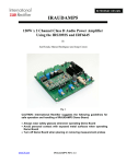
1
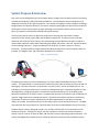
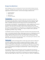
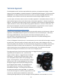
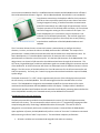
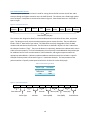
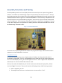
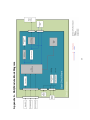
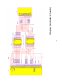
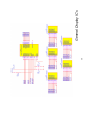
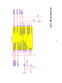
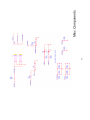
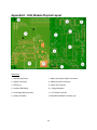
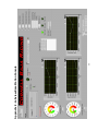
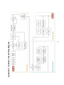
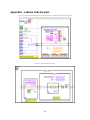
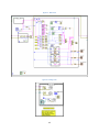
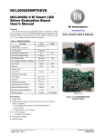
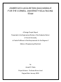
Technical Approach
The DAQ Module and PC interfaces required distinctly separate, yet complementary design. A block
diagram of the DAQ Module is included in Appendix A - DAQ Module Block Diagram. The purpose of the
DAQ Module is to acquire the data from the sensors, process it, display any debug indications via the
LED display, store the data to the SD card, and transmit the data through a Zigbee transceiver.
A screen capture of the base station console is included in Appendix E - Labview Base Station Console. A
high-level flow diagram of the console functionality is illustrated in Appendix F - Labview Console Flow
Diagram. The purpose of the base station console is to provide a serial interface to a Zigbee RF Modem,
capture all data to a .txt file, and to provide some graphical indications in “real-time” of the data. The
data cannot be displayed in real-time because the DAQ Module is programmed to transmit in packet
bursts. The received data therefore cannot be considered true real-time data.
DAQ Module Physical Design and Construction
The basis for the DAQ Module is based around the microcontroller selection and architecture. Refer to
Appendix D - DAQ Module Physical Layout for an illustration of the actual board layout. A Microchip
Technology PIC18LF4585-I/P is the centerpiece of the board, indicated by marker (1). The
microcontroller is connected to three input signals to capture the CVT-speed, sparkplug ignition
frequency, and driver dash button activity.
A Cherry Hill Magnetic-Proximity Sensor is mounted securely near the drive shaft of the engine, aimed at
the drive shaft. With each rotation of the drive shaft, the CVT rotates. With a fixed gear ratio, the
driven axle speed can be calculated. The driven axle speed, along with the tire diameter can be used to
calculate the number of rotations the tires experience. This correlates directly to the speed of the
vehicle assuming there is no slip between the tires and the ground. This implies that the speed
experiences a margin of error when the car is in the air or on slippery terrain.
The engine used in the Cornell University Baja vehicle is a Briggs & Stratton 10 hp OHV Intek, as
regulated by SAE Competition rules. A picture of the
engine is shown in Figure 2 - Briggs & Stratton 10 HP OHV
Intek Engine. To capture the tachometer data, a single
wire is wrapped around the base of the sparkplug in the
engine. As the engine fires, the wire will acquire a voltage
based on Lenz’s Law. As the sparkplug fires, the current
through the engine causes a potential voltage in the wire
by the magnetic field it creates. The sparkplug fires at
fairly regular intervals, increasing as more energy is
demanded of the engine. The timing of the intervals can
be captured to determine the Engine RPM. It is important
to note that the engine can create very high potentials on the
Figure 2 - Briggs & Stratton 10 HP OHV Intek
Engine
wire this way. While the exact amplitude is irrelevant for
calculating the Engine RPM, it may cause damage to the DAQ Module if not accounted for. For this
12