1
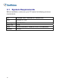
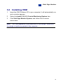
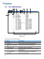
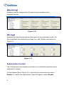
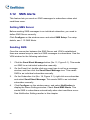
Chapter 3
Vital Sign Monitor
Vital Sign Monitor (VSM) applies to the center monitoring station where
multiple GV-Systems are being monitored. When alert events occur in a
GV-System, VSM will receive alert text messages, computer alarms and/or
output alarms, while a SMS and E-Mail message being sent out to
subscribers.
3.1
System Requirements
Before installation, make sure your PC meets the following minimum
requirements:
OS
Windows 2000, Windows XP, Server 2003
CPU
Pentium 4, 2.4G
Memory
512 MB RAM
Hard Disk
60GB
VGA
NVIDIA GeForce II 32MB at 1024 x 768 resolution
Network
TCP/IP
72
3
3.2
1.
Vital Sign Monitor
Installing VSM
Insert the CMS Software CD to your computer. It will automatically run
and a window appears.
2.
3.
Select the Install V 8.0.0.0 Central Monitoring System item.
Click Vital Sign Monitor System, and follow the on-screen
instructions.
Note:
The VSM application is provided with a USB dongle. Make sure
the dongle is tightly connected to the computer.
73
3.3
The VSM Window
12 13
1
2
3
4
5
14
6
16
15
7
9
8
17
11
10
18
19
Figure 3-1
The controls on the VSM window:
No.
1
2
3
4
5
6
74
Name
Start/Stop Service
Account
Show/Hide Subscriber
List
View Event Log
Force Output
View Subscriber
Information
Description
Starts or stops the VSM service.
Adds, deletes or modifies subscribers.
Shows and hides the Subscriber List.
Launches Event Log Browser.
Activates manually output devices to alert the
VSM operator.
Accesses the subscriber’s storage and
monitoring information.
3
Vital Sign Monitor
7
ID
Enter an ID for further search.
8
View Subscriber
Enter an ID, and then click this button to view the
Address Book
subscriber’s address book.
9
View Subscriber Status Enter an ID, and then click this button to see the
subscriber’s status.
10 Send E-Mail
Sends e-mails to subscribers.
11 Send Short Message
Sends SMS to subscribers.
12 Flag
Flags an event for later reference.
13 ID
Indicates the subscriber’s ID.
14 Type
Indicates the event types, including System,
Connection, Login/Logout, Motion, Trigger, and
Alarm.
15 Message
Indicates associated information for each event
16 Message Time
Indicates the VSM’s time when receiving the
type.
event message.
17 Start Time
Indicates the subscriber’s time when sending out
the event message.
18 Subscriber List
Displays all created groups and subscribers.
Right clicking any subscriber can call up a menu
to select the control No. 8, 9,10 and 11.
19 Event List
Displays a list of events occurred.
A list of Types and Messages will be displayed on VSM:
Type
Message
Motion
Camera xx detected Motion.
Trigger
Module xx-Input xx Triggered; Module xx-Input xx Trigger
Resume.
Connection
Camera xx Video Lost; Video Signal of Camera xx has resumed;
Module xx Lost; Module xx has resumed to normal.
Alarm
There isn’t enough space for recording; Connection Lost;
Multicam Surveillance System has been closed; Status change of
75
monitoring cameras: on: camera xx, off: camera xx; Keep Days
(xx) Alarm of Video Log is lower than xx days; Schedule
Start/Stop; An unexpected error occurred in Mulicam Surveillance
System (Error Code: 1 or 2); There is an intruder; Missing Object;
Unattended Object; Alert Message of POS; Scene Change.
Login/Logout Login; Logout.
System
Start/End Service; Fail to Start Service; Stop all camera
monitoring; Start all camera monitoring; Start monitoring all type
events; Stop monitoring all type events; Subscriber session is not
established. Wait-time expired; Unexpected logout before
subscriber session is completed.
Note:
Error Code 1 indicates a codec error; Error Code 2 indicates that
users can’t write or record any data due to HD failure or user privilege.
76
3
3.4
Vital Sign Monitor
Creating a Subscriber Account
The VSM can serve up to 1,000 subscribers at a time.
subscriber before starting VSM services.
Create at least one
To create a subscriber, follow
these steps:
1.
On the VSM widow, click the Account button (No. 2, Figure 3-1) to
display the Address Book window.
Figure 3-2
2.
3.
Click the Add A Group button
Click the Add A Subscriber button
to create a group folder.
to display the Subscriber
Address Book dialog box.
4.
Enter a login ID and password (required). Those will be the ID and
Password for the subscriber to log in to the VSM. See Figure 3-4.
5.
Enter the subscriber’s contact information in the rest of fields
(optional).
If you wish to send e-mail alerts to this subscriber, type its e-mail
address. For e-mail settings, see E-Mail Alerts later in this
chapter.
If you wish to send SMS alerts to this subscriber, type its country
code and mobile number. For SMS server settings, see SMS
Alerts later in this chapter.
6.
Click OK. This adds the subscriber to the group folder created before.
Returning to the VSM window, you will see a message: Add a
subscriber – xxx. (Subscriber xxx has been added.)
77
3.5
Creating a Subscription Schedule
The VSM operator can create schedules to monitor subscription status.
When subscribers don’t log in the VSM on the programmed time, the
operator and subscribers can get notified.
•
To set up a schedule, see 1.4 Creating a Subscription Schedule.
•
When a subscriber doesn’t log in the VSM on time, this message will
appear on the Event List: Subscriber session is not established.
Wait-Time expired.
When a subscriber logs out suddenly during a service time, this
message will appear: Unexpected logout before subscriber session is
completed.
•
To activate the computer and output alarm to notify the operator while
a SMS and E-mail message being sent out to a subscriber, use the
Notification feature.
this chapter.
78
For details, see Notification Settings later in
3
3.6
Vital Sign Monitor
Configuring VSM
On the window menu, click Configure to see these options: (1) System
Configure, (2) Password Setup, (3) Event Log Settings, (4) Notification and
(5) Local I/O Device. These options are discussed in this section.
System Configuration
Click Configure on the window menu, and then select System Configure
to open this dialog box:
Figure 3-3
79
[Startup]
Auto Run when Windows starts:
Automatically runs VSM at
Windows startup.
Start Service when Vital Sign Monitor starts:
Automatically starts
the service when VSM starts.
Login SMS Server when Service starts:
Automatically logs in the
SMS Server when the VSM service starts. You will be prompted to
enter the related information of the SMS server.
[Connective Port]
Sets the communication port to match that of the
subscriber, or keep it as default. To automatically configure the port to your
router by UPnP technology, click the Arrow button. For details on UPnP,
see UPnP Settings, Chapter 6, User’s Manual on the Surveillance System
Software CD.
[Camera Motion]
Post-Motion:
Specify the duration of the highlighted text for the
incoming message upon motion detection.
Alerts Interval:
Enable and specify the interval between the
incoming messages upon motion detection.
[Enhance network security]
Enable to enhance Internet Security.
Please notice when this feature is enabled, the subscribers using earlier
version than version 7.0 cannot access the VSM any more.
Password Settings
You can set an administrator password to prevent others from changing
your settings by accident.
Setup.
Click Configure and then select Password
To start the password feature, click Service and then select Logout
Administrator. Users can still start monitoring but will not be allowed to
change settings or stop monitoring. To change settings, click Service on the
window menu and then select Login as Administrator.
80
3
Vital Sign Monitor
Event Log Settings
Click Configure on the window menu, and select Event Log Settings to
display the Event Log Settings dialog box. The settings are the same as
those in Center V2. See “Event Log Settings”, 1.8 Event Log Browser.
Also see 3.9 Event Log Browser.
Notification Settings
VSM can automatically activate the assigned computer and output alarm to
notify the operator while a SMS and e-mail message being sent out to
subscribers, when any of these alert conditions occur: (1) Video Lost, (2)
I/O Module Lost, (3) I/O Trigger (Normal), (4) I/O Trigger (Emergency), (5)
Connection Lost, (6) Surveillance System Abnormality, (7) Intruder, (8)
Missing Object, (9) Unattended Object, (10) Scene Change, (11) POS Loss
Prevention, (12) Disk Full, (13) Stop All Camera Monitoring, (14) Stop I/O
Monitoring, (15) Subscriber Login, (16) Subscriber Logout, (17) Login Fail in
Surveillance System, (18) Start Monitoring All Type Events, (19) Stop
Monitoring All Type Events, (20) Wait-Time Expired, (21) Unexpected
Logout.
For this application, click Configure on the window menu and select
Notification to display the Alarm Settings window. The settings are the
same as those in Center V2. See 1.11 Notification Settings.
Also see 3.11 Output Alerts, 3.12 SMS Alerts, and 3.13 E-Mail Alert.
81
3.7
Starting VSM
After subscriber accounts are created, the VSM is ready to provide services.
Clicking the Start/Stop Service button (No. 1, Figure 3-1) on the VSM
window to receive signals from subscribers.
3.8
Connecting to VSM
To configure GV-System in order to access the VSM remotely through a
network connection, follow these steps:
1.
Click the Network button, and select Connect to VSM. This dialog
box appears.
Figure 3-4
2.
Type the IP address of the VSM, the User ID and Password created in
the VSM. See Creating a Subscriber Account earlier in this chapter.
3.
Click the Connect button. Make sure that the VSM is also started for
the connection.
82
3
Vital Sign Monitor
Advanced Settings for Subscription
To further define the communication conditions between the subscriber and
VSM, click the Advance button on the Connect to Vital Sign Monitor dialog
box (Figure 3-4) to display the Advanced Settings dialog box. There are
these tabs on it: (1) General, (2) Camera, (3) System Information and (4)
I/O Device.
[General]
The settings define the retry mode and communication port between
GV-System and VSM.
Figure 3-5
[Connective Port]
Sets the communication port to match that of VSM.
[Connection Broken]
Specify the number of retries and the retry interval
when the connection is not immediately available.
83
[Camera]
The settings define which camera condition to notify the VSM. To configure
the even type, first disable the Monitoring all type events option in Figure
3-4.
Figure 3-6
84
3
Vital Sign Monitor
Notify Vital Sign Monitor when Motion is Detected:
Notifies the
VSM when any selected camera detects motion. Click the Set
Camera(s) button to select desired cameras for the application.
Event Type:
If the subscriber wants the VSM always to get notified of
motion detection, select Emergency. If the subscriber wants the VSM
to get notified of motion detection only when an assigned input is
triggered, select Normal.
Notify Vital Sign Monitor when the following events come up:
Notifies the VSM when any alert event occurs, including Intruder,
Missing Object, Unattended Object and Scene Change.
Event Type:
If the subscriber wants the VSM always to get notified of
these alert events, select Emergency. If the subscriber wants the VSM
to get notified of these alert events only when an assigned input is
triggered, select Normal.
Note:
To set an input trigger for the notification of Normal events, see
[Security Service] in I/O Device below.
85
[System Information]
Figure 3-7
[Video/Audio Log]
Notifies the VSM when the duration of the video/audio
logs is less than the specified days.
[Storage Information]
Allows the VSM to inquire the subscriber’s storage
information, and get the report of free storage space. When this option is
enabled, you will see the message “Free Disk Space xx” on the VSM Event
List window.
[Adjust Time]
Enables the time increment/decrement of minutes and
seconds at the subscriber site to match the time at the VSM.
[Lose Prevention of POS]
Notifies the VSM when abnormal POS
transactions occur.
Note:
When the Adjust Time option is checked, the function of time
synchronization will be activated as soon as the VSM is started up, and it
will be re-activated every 24 hours.
86
3
Vital Sign Monitor
[I/O Device]
The settings define which I/O condition to notify the VSM. To configure
these settings, first disable the Monitoring all type events option in Figure
3-4.
Figure 3-8
[I/O Device]
Notifies the VSM when I/O devices are triggered. Use the
Arrow buttons to configure each I/O device, or click the Finger button to
apply to all I/O devices.
Allow Vital Sign Monitor to Enable / Disable I/O:
Allows the VSM
manually arm/disarm any I/O devices at the subscriber’s site without
interrupting the monitoring.
87
For example, when an alarm is triggered at the subscriber site, the
VSM operator can turn it off remotely before arriving at the site.
Meanwhile, GV-System still remains on monitoring.
Notify Vital Sign Monitor when I/O is Triggered:
Notifies the VSM
when any selected input is triggered.
Event Type:
If the subscriber wants the VSM always to get notified
of the input trigger, select Emergency. If the subscriber wants the
VSM to get notified of the input trigger only when an assigned input is
triggered, select Normal.
Right Arrow button:
Sets the delay time to notify the VSM of the
input trigger. This feature is only available when the Normal type is
chosen.
Exit Delay:
While the system is activated, this feature provides
an interval of time for the subscriber to exit the premises. During
this time, the specified input (e.g. a exit/entry door) is inactive.
Once the exit delay expires, the input will be fully armed.
Entry Delay:
While the system is activated, this feature
provides an interval of time for the subscriber to entry the
premises. During this time, the specified input (e.g. a exit/entry
door) is inactive so that the subscriber can disarm the system. If
the subscriber fails to do, once the entry delay expires, the VSM
will get notified of the input trigger.
Output Module:
Enables the assigned output module when the
selected input module is triggered.
For this example, when the I/O Device (Module 1, Input 4) is triggered,
the Output (Module 1, Pin 3) will be activated simultaneously.
Event Type:
If the subscriber wants the VSM always to get notified
of the output trigger, select Emergency. If the subscriber wants the
VSM to get notified of the output trigger only when an assigned input is
triggered, select Normal.
88
3
Right Arrow button:
Vital Sign Monitor
Sets the delay time to trigger the assigned
output module. This feature is only available when the Normal type is
chosen. The Exit Delay and Entry Delay options are similar to those
described in the input trigger.
Note:
To set an input trigger for the notification of Normal events, see
[Security Service] below.
Allow Vital Sign Monitor to Force Output:
Allows the VSM
operator to manually force output devices installed at the subscriber’s
site.
[Security Service]
Supports two types of access control systems:
Momentary and Maintained mode. For details, see [I/O Device], 1.7
Connecting to Center V2.
Detecting Input Status
The feature is designed to monitor all inputs for a change of state whenever
the subscriber starts the VSM monitoring. A change from the previously
defined state (N/O to N/C or N/C to N/O) will activate an alarm condition.
Click
on the Connect to Vital Sign Monitor dialog box (Figure 3-4).
For details, see Detecting Input Status, Chapter 2, User’s Manual on the
Surveillance System Software CD.
89
3.9
Event Log Browser
To launch Event Log Browser, click Tools on the window menu and select
Event Log Browser.
This feature is the same as that in Center V2.
See
1.8 Event Log Browser.
Also see Event Log Settings later in this chapter.
3.10
Monitoring Subscribers
Viewing Subscriber Status
To view the subscriber status, highlight one online subscriber on the VSM
window, and then click the View Subscriber Status icon (No. 9, Figure 3-1)
on the toolbar.
The following window appears.
Figure 3-9
90
3
[Subscriber]
Vital Sign Monitor
Indicates the subscriber’s ID. You can change the
subscriber by clicking the […] button.
[Video Log Storage]
Indicates the information of video log and hard disk
space.
For this, subscribers must grant the privilege first. See [System Information]
in Figure 3-7.
[Status]
Indicates the icon meanings.
[I/O Device]
Force Output:
To enable this tab, highlight one output from the tree
list, and click this tab to force the output at the subscriber site.
For this, the subscriber must grant the privilege first. See the Allow
Vital Sign Monitor to Force Output option in Figure 3-8.
Enable/Disable I/O:
Allows the VSM to arm or disarm any I/O
devices at the subscriber site without interrupting the monitoring.
For this, the subscriber must grant the privilege first. See the Allow
Vital Sign Monitor to Enable / Disable I/O option in Figure 3-8.
Viewing Storage Information
With the above Subscriber Status window, you can see one subscriber’s
storage information. When the VSM is monitoring many subscribers, the
following windows give you an overview of subscribers’ storage information
and monitoring status.
On the VSM window, click the View Subscriber Information button (No 6,
Figure 3-1) to display the following window.
91
[Monitoring]
Indicates whether camera and I/O monitoring are enabled at the
subscriber’s sites.
Figure 3-10
[Storage]
Indicates the total storage size and free space at the subscriber’s sites. For
this subscribers must grant this privilege first. See [System Information] in
Figure 3-7.
Figure 3-11
Subscription Control
The VSM operator can disable its services to an individual subscriber when
subscription expires.
On the Address Book (Figure 3-2), right-click one subscriber and select
Disable. To restore the subscription, right-click again to select Enable.
92
3
3.11
Vital Sign Monitor
Output Alerts
When alert conditions occur, you can activate the output devices installed
either at the VSM site or at the subscriber site.
Forcing Outputs of VSM
To configure output devices at the VSM site, click Configure on the window
menu and then select Local I/O Device. Currently the application only
supports GV-IO modules. For setup details, see Setting Up I/O Devices,
Chapter 2, User’s Manual on the Surveillance System Software CD.
To automatically force outputs when alert conditions occur, see Notification
Settings earlier in this chapter.
To manually force outputs, click the I/O Device button (No. 5, Figure 3-1) on
the VSM window, and then select Force Output to display the Force Output
of Local I/O Device window. Select a desired module and then click Finger
buttons to activate outputs.
Forcing Outputs of a Subscriber
See Viewing Subscriber Status earlier in this chapter.
93
3.12
SMS Alerts
This feature lets you send out SMS messages to subscribers when alert
conditions occur.
Setting SMS Server
Before sending SMS messages to an individual subscriber, you need to
define SMS Server correctly.
Click Configure on the window menu and select SMS Setup. For setup
details, see 1.12 SMS Alerts.
Sending SMS
Once the connection between the SMS Server and VSM is established,
there are several ways to send out SMS messages to subscribers. See the
VSM window for the following selections.
1.
Click the Send Short Message button (No. 11, Figure 3-1). This sends
out SMS to an individual subscriber manually.
2.
On the Event List, double-click any event type to call up a message
window, and then click the Send Short Message icon. This sends
SMS to an individual subscriber manually.
3.
On the Subscriber List (No. 18, Figure 3-1), right-click one subscriber
and select Send Short Message. This sends SMS to an individual
subscriber manually.
4.
Click Configure on the window menu, and select Notification to
display the Alarm Settings window. Check Send SMS Alerts. This
sends SMS to subscribers automatically when alert conditions occur.
See Notification Settings earlier in this chapter.
94
3
3.13
Vital Sign Monitor
E-Mail Alerts
You can send e-mails to subscribers when alert conditions occur.
Setting Mailbox
Before you can send e-mails to a separate e-mail account, you need to
define your mailbox correctly.
Click Configure on the window menu and select E-Mail Setup. For setup
details, see 1.13 E-Mail Alerts.
Sending E-Mail
There are several ways to send e-mail alerts. See the VSM window for the
following selections.
1.
Click the E-Mail button (No. 10, Figure 3-1). This sends the e-mail to
an individual subscriber manually.
2.
On the Subscriber List (No. 18, Figure 3-1), right-click one subscriber,
and then select Send E-Mail.
This sends the e-mail to an individual
subscriber manually.
3.
On the Event List, double-click one event to call up a message window,
and then click the e-mail icon. This sends the e-mail to an individual
subscriber manually.
4.
Click Configure on the window menu and select Notification to
display the Alarm Settings window. Check Send E-Mail Alerts. This
sends e-mails to subscribers automatically when alert conditions occur.
See Notification Settings earlier in the chapter.
95
96