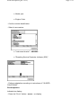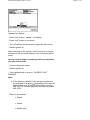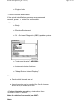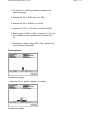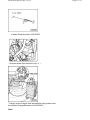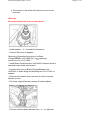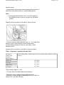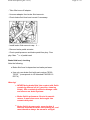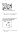
1
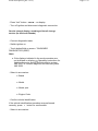
Work descriptions (part 1 of 2) Page 1 / 63 4 Work descriptions (part 1 of 2) Ball joints, visual check - Check joint boots - arrow - of ball joints for leaks and damage. Service interval display, reset Service Reminder Indicator must for Vehicle release inspection Every service Adapt - Connect diagnostic tester . - Switch ignition on. - Touch button/field on screen. "GUIDED FUNCTIONS" on screen. If the displays indicated in the work procedure are not indicated on display: Operating instructions for Vehicle Diagnosis, Testing and Information System 5051 or Vehicle Diagnosis Service Syst VAS 5052 - Press > button to confirm. - Select in succession: Brand Model Work descriptions (part 1 of 2) Model year Engine Code - Confirm vehicle identification. - Select in succession: "Instrument cluster" - ARROW - . "Resetting Service Reminder Indicator (SRI)" . - Perform adaptation according to instructions of "GUIDED FUNCTIONS" . End Adaptation Indicated on display: - Press the "Go to" button - arrow - on display. Page 2 / 63 Work descriptions (part 1 of 2) Indicated on display: - Press "exit" button - arrow - on display. - Press "exit" button in exit menu. - Turn off ignition and disconnect diagnostic connection. - Switch ignition on. After switching on the ignition, service event is no longer indicated in the odometer display in the instrument panel insert. Service interval display, recoding at delivery inspection (for USA and Canada) - Connect diagnostic tester . - Switch ignition on. - Touch button/field on screen. "GUIDED FAULT FINDING" . Note: If the displays indicated in the work procedure are not indicated on display: Operating instructions for Vehicle diagnosis, testing and information system VAS 5051 or Vehicle diagnosis and service system VAS 5052 . - Select in succession: Brand Model Model year Page 3 / 63 Work descriptions (part 1 of 2) Engine Code - Confirm vehicle identification. If the vehicle identification procedure was performed correctly, press > button for confirmation. - Select in succession: Body Electrical Equipment 01 - On Board Diagnostic (OBD) capable systems "Instrument cluster" - ARROW - . Instrument cluster functions "Adapt Service Interval Display" . Note: Check which intervals are set. Intervals must be set or recoded for first oil change service at 5,000 miles/8,000 km. - Perform Adaptation according to instructions from "GUIDED FAULT FINDING" . Note for vehicles from model year 2007: Note: Page 4 / 63 Work descriptions (part 1 of 2) For vehicles in USA and Canadian markets, the following applies: Channel 50: 50 (= 5000 miles ) for USA Channel 50: 80 (= 8000 km ) for CDN Channel 51: 372 (= 372 days ) for USA and CDN When coding to QG0 or QG2: Channels 42 + 49 are not available and are replaced with channels 50 + 51. Furthormore, when coding QG0, QG2, channels 43, 44 and 49 are deactivated End Adaptation Indicated on display: - Press the "Go to" button - arrow - on display. Indicated on display: Page 5 / 63 Work descriptions (part 1 of 2) - Press "exit" button - arrow - on display. - Turn off ignition and disconnect diagnostic connection. Service interval display, recoding at first oil change service (for USA and Canada) - Connect diagnostic tester . - Switch ignition on. - Touch button/field on screen. "ON BOARD DIAGNOSTICS (OBD)" . Note: If the displays indicated in the work procedure are not indicated on display: Operating instructions for Vehicle diagnosis, testing and information system VAS 5051 or Vehicle diagnosis and service system VAS 5052 . - Select in succession: Brand Model Model year Engine Code - Confirm vehicle identification. If the vehicle identification procedure was performed correctly, press > button for confirmation. - Select in succession: Page 6 / 63 Work descriptions (part 1 of 2) 17 "Instrument cluster" - ARROW - . 10 "Adaptation" - Select channel 49. - Enter 372. - Select channel 42. - Perform adaptation according to instructions of "ON BOARD DIAGNOSTICS (OBD)" . Note: For vehicles in USA and Canadian markets, the following applies: Channel 42: 100 (= 10,000 miles ) for USA Channel 42: 160 (= 16,000 km ) for CDN Channel 49: 372 (= 372 days ) for USA and CDN End Adaptation Page 7 / 63 Work descriptions (part 1 of 2) Indicated on display: - Press the "Go to" button - arrow - on display. Indicated on display: - Press "exit" button - arrow - on display. - Turn off ignition and disconnect diagnostic connection. Automatic transmission - 09G transmission, checking ATF level - Perform work procedure Repair Manual, 6 Spd. Automatic Transmission 09G, Repair Group 37, ATF-level, checking and topping off Battery, checking battery terminals for secure seating Special tools, testers and auxiliary items required Page 8 / 63 Work descriptions (part 1 of 2) Torque Wrench 5-50Nm VAG1331 Note: Tight fitting battery terminals guarantee proper function and a long battery service life. Perform the following work procedure: - Release latch - arrow - , flip up and remove cover toward front. - Check whether battery terminal clamps are seated securely on battery terminals by moving battery positive Page 9 / 63 Work descriptions (part 1 of 2) wire - 2 - and battery Ground (GND) wire - 1 - to and fro by hand. Warning! If the battery clamp is not seated securely on the positive terminal, disconnect battery Ground (GND) clamp on battery negative terminal first, to prevent possible accidents. If battery clamp on positive terminal is not seated securely: - First, disconnect battery clamp - 1 - from battery negative terminal. - Tighten battery clamp - 2 - on battery positive terminal to 9 Nm. - Reconnect battery clamp - 1 - on battery negative terminal and also tighten to 9 Nm. If the battery clamp on negative terminal is not seated securely: - Tighten battery clamp - 1 - on battery negative terminal to 9 Nm. - Reinstall cover. Page 10 / 63 Work descriptions (part 1 of 2) Page 11 / 63 Note: Once the battery is reconnected: Repair Manual, Electrical Equipment, Repair Group 27, . Battery, checking Battery: Checking Repair Manual, Electrical Equipment, Repair Group 27, Battery Tires, checking condition, tire wear pattern, tire pressure, tread depth Checking tire condition 01-4, Tire condition, checking . Checking tire wear pattern, checking . 01-4, Tire wear pattern, Tread depth (including spare wheel): Checking, Tread depth (including spare wheel): Checking . General notes, 01-4, 01-4, General notes . Checking tire pressure, correcting if necessary, Jetta 2006 , 01-4, Checking tire pressure, correcting if necessary, Jetta 2006 . Checking tire pressure, correcting if necessary, Jetta 2005 , 01-4, Checking tire pressure, correcting if necessary, Jetta 2005 . Special tools, testers and auxiliary items required Work descriptions (part 1 of 2) Tire inflation device VAS 5216 Tire condition, checking Warning! If damage is found, it must be checked whether a new tire must be installed. Tests during delivery inspection - Check tires (tread and side walls) for damage and remove foreign objects for example nails and glass splinters if necessary. Tests during inspection service - Check tires (tread and side walls) for damage and remove foreign objects for example nails and glass splinters if necessary. - Check tires for scuffing, one sided wear, porous side walls, cuts and fractures. Tire wear pattern, checking The wear pattern of the front wheels can be used to assess whether a check of the toe and camber is necessary: "Feathering" on tread indicates incorrect toe setting. One-sided tread wear is mainly attributed to incorrect camber. When wear of this nature is noticed, determine cause by performing alignment checks (repair measure). Tread depth (including spare wheel): Checking Page 12 / 63 Work descriptions (part 1 of 2) - Check tire tread depth Minimum depth: 1.6 mm Note: This figure may vary for individual countries according to legislation. The minimum tread depth is reached when the tires have worn down level with the 1.6 mm high tread wear indicators - arrows - positioned at intervals around the tire. If the tread depth is approaching the legal minimum permissible depth, the customer must be informed. General notes Warning! For reasons of safety only tires of same type and tread pattern should be fitted on a vehicle! On All Wheel Drive (AWD) vehicles, tires of the same type and tread pattern must be used. Otherwise the center differential may be damaged. Note: Tire inflation pressure table applies to normal tires for all factory-installed tire sizes. The pressures listed in the table are valid for cold tires. Do not reduce increased pressures on warm Page 13 / 63 Work descriptions (part 1 of 2) Page 14 / 63 tires. Tire pressures for the relevant model are on a sticker attached to the inside of fuel tank flap or on B-pillar at drivers side. Adjust tire pressure to load accordingly. The spare wheel is inflated to the maximum tire pressure specified for the vehicle. Observe that vehicles with tire pressure monitoring display, basic setting should be performed after each change in pressure, 01-5, Tire pressure monitoring display, performing basic setting . Winter tires Note: Important information on winter tires recommended by Volkswagen can be found in ELSA Win; Technical Information; Wheel and Tire Guide . For winter tires, tire pressure must be increased by 0.2 bar. Checking tire pressure, correcting if necessary, Jetta 2005 Gasoline engines 2.5 L/110 kW, Topic 01-4 . 2.0 L/147 kW FSI, Topic 01-4 . Diesel engines 1.9 L/74 kW TDI, Topic 01-4 . Gasoline engine Tire sizes Displacement/Performance 2.5 L/110 kW half load full load front rear front (bar / kpa / (bar / kpa / (bar / kpa / rear (bar / kpa / Work descriptions (part 1 of 2) Page 15 / 63 psi) 2.3 / 230 / 33 psi) 2.3 / 230 / 33 psi) psi) 2.3 / 230 / 33 2.3 / 230 / 33 205/55 R 16 2.3 / 230 / 33 2.3 / 230 / 33 2.3 / 230 / 33 2.3 / 230 / 33 225/45 R 17 2.3 / 230 / 33 2.3 / 230 / 33 2.3 / 230 / 33 2.3 / 230 / 33 2.4 2.4 2.6 3.0 4.2 4.2 4.2 4.2 195/65 R 15 225/40 R 18 92 Y (XL) Spare wheel (collapsible spare wheel) Gasoline engine Displacement/Performance 2.0 L/147 kW Tire sizes half load full load front (bar) 205/55 R 16 91 W rear (bar) 2.4 front (bar) rear (bar) 2.6 3.0 2.4 225/45 R 17 91 W, Y 2.4 2.4 2.6 3.0 225/40 R 18 92 Y (XL) 2.4 2.4 2.6 3.0 4.2 4.2 4.2 4.2 Spare wheel (collapsible spare wheel) Diesel engine 195/65 R 15 Displacement/Performance 1.9 L/74 kW TDI half load full load front rear front rear (bar / kpa / (bar / kpa / psi) (bar / kpa / (bar / kpa / psi) psi) psi) 2.2 / 220 / 32 2.0 / 200 / 29 2.4 / 240 / 34 2.9 / 290 / 42 205/55 R 16 2.2 / 220 / 32 2.0 / 200 / 29 2.4 / 240 / 34 2.9 / 290 / 42 225/45 R 17 2.2 / 220 / 32 2.0 / 200 / 29 2.4 / 240 / 34 2.9 / 290 / 42 4.2 4.2 4.2 4.2 Tire sizes Spare wheel (collapsible spare wheel) Checking tire pressure, correcting if necessary, Jetta 2006 Gasoline engines Work descriptions (part 1 of 2) 2.0 L/147 kW, Page 16 / 63 Topic 01-4 . Diesel engines 1.9 L/77 kW TDI, Topic 01-4 . Gasoline engine Displacement/Performance 2.0 L/147 kW Tire sizes half load front (bar) 205/55 R 16 91 W full load rear (bar) 2.4 front (bar) rear (bar) 2.6 3.0 2.4 225/45 R 17 91 W, Y 2.4 2.4 2.6 3.0 225/40 R 18 92 Y (XL) 2.4 2.4 2.6 3.0 4.2 4.2 4.2 4.2 Spare wheel (collapsible spare wheel) Diesel engine Displacement/Performance 1.9 L/77 kW TDI Tire sizes half load 195/65 R 15 91 H, V full load front (bar) rear (bar) front (bar) rear (bar) 2.2 2.2 2.4 2.9 205/55 R 16 91 V, W 2.2 2.2 2.4 2.9 225/45 R 17 91 W, Y 2.2 2.2 2.4 2.9 225/40 R 18 92 Y (XL) 2.2 2.2 2.4 2.9 4.2 4.2 4.2 4.2 Spare wheel (collapsible spare wheel) Brake fluid, changing Warning! NEVER bring brake fluid into contact with fluids containing mineral oil (oil, gasoline, cleaning fluids). Oils containing minerals damage seals and sleeves on brake systems. Brake fluid is poisonous. Due to its caustic nature, it must also never be brought into contact with paint. Work descriptions (part 1 of 2) Brake fluid is hygroscopic, meaning that it absorbs moisture from the surrounding air, and must therefore always be stored in air-tight containers. Rinse off any spilled brake fluid using plenty of water. Observe disposal regulations! Special tools, testers and auxiliary items required Brake Charger/Bleeder Unit VAS5234 or brake charger/bleeding unit V.A.G 1869 Upgrade kit and extraction unit V.A.G 1869/4 Page 17 / 63 Work descriptions (part 1 of 2) Brake Pedal Actuator VAG1869/2 - Unscrew brake fluid reservoir cap - 1 - . - Extract as much brake fluid as possible using intake hose from Brake Charger/Bleeder Unit VAS5234 . Note: Page 18 / 63 Work descriptions (part 1 of 2) The strainer in the brake fluid reservoir must not be removed. Warning! Extracted brake fluid must not be reused! - Install adapter - 1 - on brake fluid reservoir. - Connect filler hose to adapter. Observe Operating instructions for Brake Charger/Bleeder Unit VAS5234 or operating instructions for V.A.G 1869 ! - Install Brake Pedal Actuator VAG1869/2 between drivers seat and brake pedal, and tension. - Connect filler hose of Brake Charger/Bleeder Unit VAS5234 or brake filling and bleeding tool V.A.G 1869 to adapter. - Remove both wheels from rear axle in order to access bleeder screws. - Pull cover caps off bleeder screws of brake calipers. - Connect collector bottle bleeder hose - 1 - to right rear Page 19 / 63 Work descriptions (part 1 of 2) Page 20 / 63 bleeder screw. - Open bleeder screw and let the corresponding amount of brake fluid (see table) flow out. Close bleeder screw. Note: Use appropriate bleeder hose. It must fit tightly on the bleeder screw so that no air gets into the brake system. Repeat work procedure on left side of vehicle at rear. - Connect collector bottle bleeder hose - 1 - to a right front bleeder screw, open bleeder screw and allow the corresponding quantity to flow out (see table). Close bleeder screw. Repeat work procedure on left side of vehicle at front. Table - Sequence / quantity of brake fluid Sequence: wheel brake cylinder, brake calipers Brake fluid quantity which must flow out of wheel brake cylinders or brake calipers: Right rear 0.25 Liter Left rear 0.25 Liter Right front 0.25 Liter Left front 0.25 Liter Total quantity: approx. 1 liter - Fit cover caps to brake caliper bleed screws. - Move filler lever on Brake Charger/Bleeder Unit VAS5234 or brake filling and bleeding tool V.A.G 1869 to position "B" (see user manual). Work descriptions (part 1 of 2) - Take filler hose off adapter. - Unscrew adapter from brake fluid reservoir. - Check brake fluid level and correct if necessary. - Install brake fluid reservoir cap - 1 - . - Remove brake pedal actuator. - Check pedal pressure and brake pedal free play. Free play: Max. 1 / 3 of pedal travel Brake fluid level, checking Note the following: Brake fluid level is dependent on brake pad wear. Use only new brake fluid with part number "B 000 750 M" . (corresponds to US standard FMVSS 116 DOT 4) Warning! NEVER bring brake fluid into contact with fluids containing mineral oil (oil, gasoline, cleaning fluids). Oils containing minerals damage seals and sleeves on brake systems. Brake fluid is poisonous. Due to its caustic nature, it must also never be brought into contact with paint. Brake fluid is hygroscopic, meaning that it absorbs moisture from the surrounding air, and must therefore always be stored in air-tight Page 21 / 63 Work descriptions (part 1 of 2) containers. Rinse off any spilled brake fluid using plenty of water. Observe disposal regulations! Brake fluid level during delivery inspection: - For the delivery inspection the fluid level must lie at the MAX. marking - 1 - . Note: The MAX. marking - 1 - must not be exceeded, this will ensure that the brake fluid will not overflow the reservoir. Brake fluid level during inspection service: The fluid level must always be judged in conjunction with brake pad wear. When vehicle is in use, the fluid level tends to drop slightly due to brake pad wear and automatic adjustment. Recommended brake fluid level when brake pads are almost at wear limit: Page 22 / 63 Work descriptions (part 1 of 2) "At MIN marking or just above" - 2 - , "NO FILL UP IS NECESSARY" . Recommended brake fluid level when brake pads are new or well above wear limit: "Between MIN and MAX marking" . Warning! If fluid level is below MIN. marking - 2 - , brake system must be checked before brake fluid is added "repair measure" Brake system, performing visual check for leaks and damages Check the following components for leaks and damages: Master brake cylinder Brake booster (with Anti-lock Brake System (ABS): Hydraulic unit) Brake pressure regulator and Brake calipers - Ensure that brake hoses are not twisted. - Ensure that brake hoses do not touch any vehicle components when steering is at full lock. - Check brake hoses are not porous or brittle. - Check brake hoses and pipes for chafing. Page 23 / 63 Work descriptions (part 1 of 2) - Check brake connections and methods of securing for correct seating, leaks and corrosion. Warning! Malfunctions found must be rectified (repair measure). Brake pads front and rear, checking thickness Special tools, testers and auxiliary items required Torque Wrench 40-200Nm VAG1332 Electric hand flashlight and mirror Perform the following work procedure: The adapter to loosen/tighten the anti-theft wheel bolts is located in the vehicle tool kit, 01-5, Break-down set, checking . Front disc brake pads: - For better judgement of remaining pad thickness remove the front wheel on the drivers side. - Pull off wheel bolt caps if necessary, 01-5, Wheel securing bolts, tightening to correct torque setting . - Mark position of wheel in relation to brake disc. - Unbolt wheel securing bolts and remove wheel. Page 24 / 63 Work descriptions (part 1 of 2) - Measure inner and outer pad thickness. a - Pad thickness without backing plate Wear limit: 2 mm With a pad thickness of 2 mm (without backing plate) the brake pads have reached their wear limit and must be replaced (repair measure). Inform customer! Note: When replacing brake pads, it is absolutely necessary to check brake discs for wear! Checking and if necessary replacing brake discs is a repair measure. - Check brake disc for wear Repair Manual, Brake System, Repair Group 46, Front brakes, servicing - Install wheel to marked position. - Tighten wheel securing bolts in diagonal sequence, tightening torque, 01-5, Wheel securing bolts, tightening to correct torque setting .. - Store adapter with vehicle tool kit after completing work. - Reinstall wheel bolt covers if necessary. Rear disc brake pads: - Illuminate area behind hole in wheel using an electric hand flashlight. - Determine thickness of outer pad by checking visually. Page 25 / 63 Work descriptions (part 1 of 2) Page 26 / 63 - Illuminate inner pad using an electric hand flashlight and mirror. - Determine thickness of inner pad by checking visually. a - Inner and outer pad thickness without backing plate Wear limit: 2 mm With a pad thickness of 2 mm (without backing plate) the brake pads have reached their wear limit and must be replaced (repair measure). Inform customer! Note: When replacing brake pads, it is absolutely necessary to check brake discs for wear! Checking and if necessary replacing brake discs is a repair measure. - Check brake disc for wear Repair Manual, Brake System, Repair Group 46, Rear brakes, servicing Climatronic, setting temperature to 72 - Switch on ignition. F (22 C) Work descriptions (part 1 of 2) Page 27 / 63 - Turn switch - 4 - on driver side until 72 F (22 C) appears in display - 1 - (clockwise warm, counterclockwise cold). - Turn switch - 3 - on passenger side until 72 F (22 appears in display - 2 - (clockwise warm, counterclockwise cold). C) - Switch off ignition. 6-speed Direct shift transmission 02E, changing oil and filter Work procedure: Repair Manual, 6 Spd. Direct Shift Automatic Transmission 02E Front Wheel Drive, Repair Group 34, . Electric window regulators, checking positioning Note: After disconnecting and reconnecting the battery, the run-up and run-down function of the power window regulators will not function. Therefore, the electric windows must be positioned again immediately, before a new vehicle is delivered. The vehicle battery must not be disconnected after the electric windows have been positioned. Warning! After disconnecting and reconnecting the battery, pinch protection of the power window regulators will not function. This can cause serious injuries if e.g. fingers are caught in the window! Work descriptions (part 1 of 2) Page 28 / 63 Perform the following work procedure to position the electric windows: Note: The following work sequence is for the left front window. The positioning for the remaining windows is performed in the same manner using the respective switch in the drivers door. - Switch on ignition - Close all doors and windows completely. - Fully close left front side window by pulling and holding switch (for more than 1 second) in position "Close" . - Lift switch again for 1 second. Now, when the switch is pressed briefly, the side window will automatically lower fully and when the button is lifted briefly the window will automatically raise fully. - Switch off ignition. Vehicle system test, performing - Connect diagnostic tester connecting 01-3, Diagnostic tester, - Switch on ignition - Select mode "Guided Fault Finding" on display. - Perform vehicle identification via tester. Program now automatically performs a vehicle system test and checks all possible control modules installed in this model. - Press button > . All malfunctions are listed. Note: At this point, it is useful to switch to operating mode Guided Functions in order to perform further work using VAS 5051/VAS 5052 and to avoid a second vehicle identification via tester. To do so, press Operating Mode button and menu item Guided Functions. Work descriptions (part 1 of 2) Further work procedures can be taken from the corresponding work descriptions. To return to operating mode Guided Fault Finding, press Operating Mode button, then press Guided Fault Finding. Caution! The vehicle must always be passed on to the customer with DTC memory erased. Static malfunction If there are one or more static malfunctions stored in DTC memory, it is recommended to repair these malfunctions via Guided Fault Finding, upon approval by the customer. Sporadic malfunction If there are only sporadic malfunctions or notes stored and the customer does not complain about problems regarding an electronic vehicle system, erase DTC memory. - Press button > once again to access the test plan. - End Guided Fault Finding via button Go To and then press End. Once again, all DTC memories are checked. The window displayed now shows all sporadic malfunctions were erased. The diagnostic report will be sent "online" or stored in tester. Note: If the tester is not connected to the network, the diagnostic report will be stored and sent as soon as the tester is connected to the network. Stored reports older than 40 days will be erased automatically. The vehicle system test is completed. CV joint boots, visual check Perform the following work procedure: Page 29 / 63 Work descriptions (part 1 of 2) - Check outer and inner CV joint boots - arrows - for leaks and damage. Ribbed belt, checking condition Perform the following work procedure: - Crank engine at harmonic balancer/belt pulley using a socket wrench. Check ribbed belt - 1 - for: Sub-surface cracks (cracks, core ruptures, cross sectional breaks) Layer separation (top layer, cord strands) Base break-up Fraying of cord strands Flank wear (material wear, frayed flanks, flank brittleness -glassy flanks-, surface cracks) Page 30 / 63 Work descriptions (part 1 of 2) Traces of oil and grease Note: It is essential to replace ribbed belt if malfunctions are found. This will avoid possible break-downs or operating problems. The replacement of a ribbed belt is a repair measure. Instrument cluster, adapting language Note: The vehicle electronics and range of equipment determine which menus will be shown in the display. 1. Bringing up main menu on vehicles without multifunction steering wheel - Switch ignition on. A vehicle pictogram will appear. - Press button - A - once in windshield wiper lever. - To move back out of another menu into the main menu, hold rocker switch - B - depressed for two seconds. This procedure might have to be repeated until the main menu appears. 2. Bringing up menu "Settings" - Press upper or lower rocker switch to select menu item. The selected menu item is located between both horizontal lines, a triangle is located at the right. - Select menu item "Settings" . Page 31 / 63 Work descriptions (part 1 of 2) Page 32 / 63 - Press button - A - once in windshield wiper lever. Menu "Settings" is brought up. The following indications are shown in the Settings menu: Settings for time Speed warning for winter tires Units Language Auxiliary heater Light View and Comfort 3. Bringing up menu "Language" Select menu item "Language" and confirm using - A button - . Several languages are displayed in the menu. Select desired language and confirm using - A button - . Compass, adapting compass zone and calibrating compass General Information, 01-4, General Information . Adjusting compass zone, adapting . Calibrating compass, 01-4, Compass zone, 01-4, Compass, calibrating . General Information Note: Only for vehicles with Highline instrument cluster! The compass indicates the direction in which the vehicle drives. Work descriptions (part 1 of 2) To get a correct indication, the correct geographical zone must be adapted. - Determine geographic area referring to zone map, e.g. zone 8 for Germany, zone 6 for Mexico etc. Adapting compass zone and calibrating compass is Page 33 / 63 Work descriptions (part 1 of 2) performed using button - A - and rocker switch - B - of windshield wiper lever in "main menu" . Button - A - serves to confirm menu items. Rocker switch - B - serves to switch menus. Compass zone, adapting 1. Bringing up the main menu - Switch ignition on. A vehicle pictogram will appear. - Press button - A - once in windshield wiper lever. - To move back out of another menu into the main menu, hold rocker switch - B - depressed for two seconds. This procedure might have to be repeated until the main menu appears. 2. Bringing up menu "Settings" - Press upper or lower rocker switch to select menu item. The selected menu item is located between both horizontal lines, a triangle is located at the right. - Select menu item "Settings" . Page 34 / 63 Work descriptions (part 1 of 2) - Press button - A - once in windshield wiper lever. Menu "Settings" is brought up. 3. Bringing up menu "Comfort" - Select menu item "Comfort" using rocker switch - B - . Menu "Comfort" is brought up. 4. Bringing up menu "Compass" - Select menu item "Compass" using rocker switch - B - . Menu "Compass" is brought up. The following indications are shown in the Compass menu: Page 35 / 63 Work descriptions (part 1 of 2) The compass direction Zone Calibration Back 5. Calling up the menu "Zone" Select menu item "Zone" and confirm using the - A button - . The following indications are shown in the Compass menu: The compass direction Zone (e.g. zone 8 for Germany, zone 6 for Mexico) (+1- zone ) the option to set 1 zone higher (-1- zone ) the option to set 1 zone lower Back - Select menu item "+ 1 zone" or "- 1 zone" using rocker switch and press button to set compass zone higher or lower, shown in display. 6. Exiting the menu - Select menu item "Back" using rocker switch - B - . - Press button - A - . Menu item "Compass" is exited and the last displayed menu is brought up. Page 36 / 63 Work descriptions (part 1 of 2) Compass, calibrating 1. Bringing up the main menu - Switch ignition on. A vehicle pictogram will appear. - Press button - A - once in windshield wiper lever. - To move back out of another menu into the main menu, hold rocker switch - B - depressed for two seconds. This procedure might have to be repeated until the main menu appears. 2. Bringing up menu "Settings" - Press upper or lower rocker switch to select menu item. The selected menu item is located between both horizontal lines, a triangle is located at the right. - Select menu item "Settings" . - Press button - A - once in windshield wiper lever. Menu "Settings" is brought up. 3. Bringing up menu "Comfort" Page 37 / 63 Work descriptions (part 1 of 2) - Select menu item "Comfort" using rocker switch - B - . Menu "Comfort" is brought up. 4. Bringing up menu "Compass" - Select menu item "Compass" using rocker switch - B - . Menu "Compass" is brought up. The following indications are shown in the Compass menu: The direction Zone Calibration Back 5. Bringing up menu "Calibration" Select menu item "Calibrating" and confirm using the - A button - . The following indications are shown in the Compass menu: To calibrate, drive in a full circle Calibrate Back 6. Bringing up menu "Calibrating" Page 38 / 63 Work descriptions (part 1 of 2) Select menu item "Calibrating" and confirm using - A button - . The following indication is shown in the Compass menu: Drive a full circle Press - A button - . - Drive full circle at a speed of less than 10 mph (20 Km/h). "CAL" is shown at the top in display, next to the arrow for direction. After completing the calibration, display "CAL" will be replaced by the actual direction (e.g. "N" for North). Cooling system, check coolant level and freeze protection Note: All engines are filled with coolant additive G 12 Plus according to TL VW 774 F (purple color ). G 12 Plus can be mixed with the previous coolant additives G 11 and G 12 (red). Ensure that the system is replenished only with G12 Plus (due to its positive properties). G 12 Plus is suitable as a filled-for-life filling for cast iron and all-aluminum engines and gives optimum protection against freeze, corrosion damage, scaling and over-heating. G 12 Plus increases the boiling point to 275 F (135 C) and ensures for a better heat dissipation. The coolant portion of the mixture must amount to at Page 39 / 63 Work descriptions (part 1 of 2) least 40 % (freeze protection to -13 F ( -25 C)) and should not exceed 60 % (freeze protection to -40 F (40 C)). Otherwise the freeze protection will be reduced and the cooling efficiency will be worsened. The freeze protection must be ensured to approximately -13 F ( -25 C). Checking freeze protection and adding coolant additive if necessary Special tools, testers and auxiliary items required Refractometer T10007 Note: Read the bright/dark boundary to obtain an accurate reading for the following tests. Place a drop of water on the glass to improve the readability of the bright/dark boundary. The bright/dark boundary can be clearly recognized on the "WATERLINE" . - Check the concentration of the coolant additive using Refractometer T10007 (operating instructions). Page 40 / 63 Work descriptions (part 1 of 2) Page 41 / 63 The scale - 1 - of the Refractometer T10007 is designed for coolant additives G 12; G12 Plus and G11. Scale - 2 - refers only to coolant additive G 13. (previously L80) Note: The freeze protection must be ensured to approximately -13 F ( -25 C). If for climatic reasons greater freeze protection is required, the amount of G 12 Plus can be increased, but only up to 60% (freeze protection to about -40 F (- 40 C)), otherwise freeze protection and cooling effectiveness will be reduced. - If freeze protection is insufficient, drain off required quantity shown in freeze protection table and add coolant additive G 12 Plus. Note: Observe waste disposal regulations! Freeze protection to F( C) Difference amount in liters Actual value Specified value 32 (0) -13 (-25) 3.5 -31 (-35) 4.0 -13 (-25) 3.0 -31 (-35) 3.5 -13 (-25) 2.0 -31 (-35) 3.0 -13 (-25) 1.5 -31 (-35) 2.0 -13 (-25) 1.0 -31 (-35) 1.5 -13 (-25) -31 (-35) 1.0 -22 (-30) -31 (-35) 0.5 -31 (-35) -40 (-40) 0.5 23 (-5) 14 (-10) 5 (-15) -4 (-20) - Check coolant additive concentration after test drive again. Work descriptions (part 1 of 2) Page 42 / 63 Checking coolant level and adding coolant if necessary - Check coolant level in expansion tank with engine cold. Delivery inspection: Coolant level above the "MIN marking" - arrow - . Inspection service: Coolant level above the "MIN marking" - arrow - . - If coolant is too low, add required amount according to mixture ratio. Note: Determine cause of fluid loss which cannot be attributed to normal use and rectify (repair measure). Mixture ratio: Freeze protection to Coolant additive G 12 Plus / TL VW 774 F Water -13 F ( -25 C) approx. 40 % approx. 60 % - 31 F (-35 C) approx. 50 % approx. 50 % - 40 F (-40 C) approx. 60 % approx. 40 % Note: Coolant additive G 12 Plus conforming to TL VW 774 F prevents freeze and corrosion damage, scaling, and raises the boiling point. For these reasons, the cooling system must be filled with radiator freeze and corrosion protection fluid all year round. Work descriptions (part 1 of 2) Especially in countries with tropical climates or when vehicle is driven under heavy load, the coolant improves the engine reliability by its increased boiling point. The coolant concentration must not be reduced by adding water, even during the warmer season. The coolant additive ratio must be at least 40%. Fuel filter, replacing Note: There are two different fuel filter systems. System 1 has a bleeder connection - 1 - , work procedures 01-4, Replacing fuel filter: Fuel filter system with bleeder connection . System 2 has "no" bleeder connection, work procedures 01-4, Replacing fuel filter: Fuel filter system without bleeder connection . Page 43 / 63 Work descriptions (part 1 of 2) Note: Make sure that diesel does not come in contact with the coolant hoses. Clean hoses immediately if necessary! Observe disposal regulations! Replacing fuel filter: Fuel filter system with bleeder connection, 01-4, Replacing fuel filter: Fuel filter system with bleeder connection . Replacing fuel filter: Fuel filter system without bleeder connection, 01-4, Replacing fuel filter: Fuel filter system without bleeder connection . Replacing fuel filter: Fuel filter system with bleeder connection Special tools, testers and auxiliary items required Suction Pump VAS5226 Note: Make sure that diesel does not come in contact with the coolant hoses. Clean hoses immediately if necessary! Observe disposal regulations! Perform the following work procedure: Page 44 / 63 Work descriptions (part 1 of 2) - Remove screw plug for water extraction - 1 - . - Connect hose of Suction Pump VAS5226 to adapter. - Extract approx. 100 ml diesel fuel using Suction Pump VAS5226 . - Replace screw plug seal of water extraction. - Tighten screw plug of water extraction to 3 Nm. - Loosen all bolts - arrows - of upper fuel filter in diagonal sequence approx. 1.5 to 2 turns. - Remove bolts completely and remove upper fuel filter. Page 45 / 63 Work descriptions (part 1 of 2) - Remove replacement filter - 1 - and seal - 2 - from lower fuel filter - 4 - . - Replace seal - 3 - . Note: Observe disposal regulations! - Install new replacement filter in lower fuel filter. - Attach new seal - 1 - onto upper fuel filter. - Place upper fuel filter with seal onto lower fuel filter. - Bolt upper fuel filter to lower fuel filter. - Tighten bolts according to sequence shown in illustration. - Tighten bolts to tightening torque of 5 Nm. Tightening sequence avoids canting of the upper fuel filter, Page 46 / 63 Work descriptions (part 1 of 2) thus preventing damages to the seal. Replacing fuel filter: Fuel filter system without bleeder connection Remove engine cover, 01-4, Upper engine cover, removing and installing . Removing: Note: Make sure that diesel does not come in contact with the coolant hoses. Clean hoses immediately if necessary! Observe disposal regulations! Perform the following work procedure: - Loosen all bolts - arrows - of upper fuel filter in diagonal sequence approx. 1.5 to 2 turns. - Remove bolts completely and remove upper fuel filter. Page 47 / 63 Work descriptions (part 1 of 2) - Remove old gasket - 2 - from upper fuel filter - 1 - . - Remove replacement filter - 3 - from lower fuel filter. Caution! If necessary, remove any dirt or water residue from lower part of fuel filter. Note: Observe disposal regulations! Installing: - Install new replacement filter in lower fuel filter. - Insert new seal - 1 - into groove of upper fuel filter arrows - . - Attach upper fuel filter with gasket onto lower fuel filter, and screw in bolts approx. 1 turn. Page 48 / 63 Work descriptions (part 1 of 2) - Bolt upper fuel filter to lower fuel filter. - Tighten bolts according to sequence shown in illustration. - Tighten bolts to tightening torque of 5 Nm. Tightening sequence avoids canting of the upper fuel filter, thus preventing damages to the gasket. Water separator, draining Note: There are two different fuel filter systems. System 1 has a bleeder connection - 1 - , work procedures 01-4, Draining fuel filter: Fuel filter system with bleeder connection . Page 49 / 63 Work descriptions (part 1 of 2) System 2 has "no" bleeder connection, work procedures and does not require draining Note: Make sure that diesel does not come in contact with the coolant hoses. Clean hoses immediately if necessary! Observe disposal regulations! Draining fuel filter: Fuel filter system with bleeder connection Special tools, testers and auxiliary items required Suction Pump VAS5226 Note: Make sure that diesel does not come in contact with the coolant hoses. Clean hoses immediately if necessary! Page 50 / 63 Work descriptions (part 1 of 2) Observe disposal regulations! Perform the following work procedure: - Remove screw plug for water extraction - 1 - . - Connect hose of Suction Pump VAS5226 to adapter. - Extract approx. 100 ml diesel fuel using Suction Pump VAS5226 . - Replace screw plug seal of water extraction. - Tighten screw plug of water extraction to 3 Nm. Air cleaner, cleaning housing and replacing filter element Removing and installing air filter element, 2.5 L engine, 01-4, Removing and installing air filter element, 2.5 L engine . Removing and installing air filter element, 2.0 L TFSI engine, 01-4, Removing and installing air filter element, 2.5 L engine . Removing and installing air filter element on vehicles with diesel engine, 01-4, Removing and installing air filter element on vehicles with diesel engine . Removing and installing air filter element, 2.5 L engine Removing - Remove engine cover, removing and installing . 01-4, Upper engine cover, - Set aside engine cover with upper side on a soft surface, avoid damages to housing. Page 51 / 63 Work descriptions (part 1 of 2) - Remove bolts - arrows - on underside of engine cover. - Flip up lower air filter housing - 1 - in direction of arrow and remove. - Remove air filter element - 1 - from lower air filter housing - 2 - . - If necessary, clean air filter housing using compressed air. Installing - Insert air filter element - 1 - into lower air filter housing 2- . Note: Page 52 / 63 Work descriptions (part 1 of 2) Make sure sealing surfaces of air filter housing are seated properly. Note: For securing upper air filter housing to lower air filter housing as well as intake tube, self-tapping bolts are used in series production. If these bolts are loosened or tightened using an electric screwdriver, the thread in the upper air filter housing may be damaged. For this reason, an electric screwdriver must only be used if the following requirements are met: Screwdriver maximum speed must not exceed 200 RPM. Tightening torque of 2 Nm max. must be adjustable. - Hook lower air filter - 1 - into retaining tabs - arrows - of upper air filter - 2 - and swing in direction of arrow, then press on lightly. Page 53 / 63 Work descriptions (part 1 of 2) Checking surface alignment of the housing halves - 1 and - 2 - (rear part): - Both housing halves must contact flush - arrows - . Checking surface alignment of housing halves - 1 and - 2 - (front part): - Both housing halves must contact flush - arrows - . - Tighten bolts - arrows - to a maximum of 2 Nm. Note: Alternately tighten bolts evenly in order to ensure both housing halves do not cant. - Install engine cover, 01-4, Upper engine cover, removing and installing . Removing and installing air filter element, 2.0 L TFSI engines Removing - Remove engine cover, removing and installing . 01-4, Upper engine cover, - Set aside engine cover with upper side on a soft surface, avoid damages to chrome trim. Page 54 / 63 Work descriptions (part 1 of 2) - Remove bolts - arrows - on underside of engine cover. - Remove lower air filter housing and remove air filter element - 2 - from upper air filter housing - 1 - . Note: For securing upper air filter housing to lower air filter housing as well as intake tube, self-tapping bolts are used in series production. If these bolts are loosened or tightened using an electric screwdriver, the thread in the upper air filter housing may be damaged. For this reason, an electric screwdriver must only be used if the following requirements are met: Screwdriver maximum speed must not exceed 200 RPM. Tightening torque of 3 Nm max. must be adjustable. - Install lower air filter housing on upper air filter housing. - Tighten bolts - arrows - to a maximum of 3 Nm. Page 55 / 63 Work descriptions (part 1 of 2) Removing and installing air filter element on vehicles with diesel engine - Remove bolts - arrows - . - Remove upper air filter housing and air filter element - 1 - . Note: Observe disposal regulations! - Clean lower air filter housing. - Insert new air filter element and attach upper air filter housing. Page 56 / 63 Work descriptions (part 1 of 2) - Tighten upper air filter housing with bolts - arrows - to 9 Nm. Engine and components in engine compartment (from above and below), performing visual check for leaks and damages Perform visual check as follows: - Check engine and components in engine compartment for leaks and damages. - Check hoses, pipes and connections of Fuel system Cooling and heating system and brake system for leaks, abrasions, porosity and brittleness. Note: Ensure that all malfunctions detected are rectified within repair measures. If fluid losses are greater than can be reasonably expected, determine cause and repair (repair measure) Upper engine cover, removing and installing Caution! Make sure engine cover is not hit by fist or tool when installed, i.e. when engaging at mounting points, there is the danger of damage. Removing and installing engine cover, 2.0 L TFSI direct fuel injection engine, 01-4, Removing and installing engine cover, 2.0 L TFSI direct fuel injection engine Removing and installing engine cover, 2.5 L fuel injection engine, 01-4, Removing and installing engine cover, 2.5 L fuel injection engine . Removing and installing engine cover, 1.9 L pump injector diesel engine, 01-4, 1.9 L pump injector diesel engine . Page 57 / 63 Work descriptions (part 1 of 2) Removing and installing engine cover, 2.0 L TFSI direct fuel injection engine Removing - Remove bolts of air intake apparatus - arrows A - . - Disconnect connector - 1 - from mass air flow sensor and lay aside. - Disengage both mounting clips - arrows A - . - Disengage engine cover - arrows 3 - first, then - arrows 4 - , and lift. Installing Page 58 / 63 Work descriptions (part 1 of 2) Installation is performed in the reverse order of removal. Removing and installing engine cover, 2.5 L fuel injection engine Special tools, testers and auxiliary items required Spring Type Clip Pliers VAS5024A VAS5024A Removing - Remove bolts of air intake apparatus - arrows A - . - Release mass air flow (MAF) sensor clamps - arrow B using Spring Type Clip Pliers VAS5024A VAS5024A and push clamps back. - Disconnect intake air hose - 1 - from mass air flow (MAF) sensor - 2 - . Page 59 / 63 Work descriptions (part 1 of 2) - Disconnect connector - arrow C - from mass air flow (MAF) sensor and lay aside. - Carefully pull engine cover at mounting points - arrows A - out of locking mechanism. - Slightly raise engine cover at front. - Carefully pull engine cover at mounting points - arrows B - out of locking mechanism. - Carefully remove engine cover upward - movement arrows - . Note: Make sure mass air flow (MAF) sensor is not damaged when removing engine cover. Installing - Position engine cover on rear mounting points - arrows B - , then on front mounting points - arrows A - . Carefully press on mounting points by hand until engine cover engages noticeably. Page 60 / 63 Work descriptions (part 1 of 2) Note: Make sure mass air flow (MAF) sensor is not damaged when engine cover is installed. The rest of the installation follows the reverse of the removal procedures. 1.9 L pump injector diesel engine Removing: Note: Engine cover consists of two parts. 1. the outer part, here shaded in illustration 2. the center part, not shaded in illustration - Carefully disengage engine cover in the following sequence at individual mounting points and lift. Page 61 / 63 Work descriptions (part 1 of 2) - 1 - ,- 3 - ,- 2 - ,- 4 - . - Remove outer part - 1 - . - Also carefully disengage center part - 2 - and remove. Installing: - Place center part - 2 - on mounting points and press on. - Place outer part - 1 - on mounting points - arrows - and press on. Lower engine compartment cover (noise insulation), removing and installing Special tools, testers and auxiliary items required Page 62 / 63 Work descriptions (part 1 of 2) Torque Wrench (5-60 Nm) VAG1783 - Remove bolts - arrows - . - Remove noise insulation. Note: The rest of the installation follows the reverse of the removal procedures. - Tighten bolts to a tightening torque of 2 Nm. Page 63 / 63