1
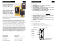
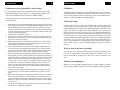
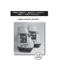
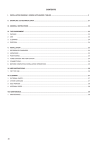
Pro Shot Alpha
Laser Operations Guide
Laser Reference, Inc.
151 Martinvale Lane
San Jose, CA. 95119—USA
Toll Free (USA) +1-800-238-0685
Telephone +1-408-361-0220
Fax +1-408-361-3180
Web www.proshotlaser.com
Email [email protected]
Customer Information
Laser Serial Number ______________________________
Receiver Serial Number ___________________________
Date of Purchase _________________________________
Revision 1.1 May 24, 2007
Warranty
13
Introduction
24 month warranty
You now own the Pro Shot Alpha, a high accuracy, servo leveled automatic
laser for the most demanding leveling or grade checking operations.
The Pro Shot Alpha laser transmitter is warranted for twenty four (24) months
from the date of new equipment purchase from an authorized dealer. During
the warranty period, Laser Reference or its authorized service center will repair
or replace, at Laser Reference’s sole discretion, laser transmitters (except for
transportation costs), if the product is found to be defective in workmanship or
materials. Maintaining the calibration of the laser is not the responsibility of
Laser Reference or its authorized service centers. If service is needed, the product must be sent FREIGHT PREPAID to the nearest authorized service center
or to Laser Reference.
Please take a moment to read this manual. It contains vital information on
safely operating and getting the best results from your new laser.
Alpha Specifications
Contents:
Case Contents …………………………………………….
1
Battery Installation ………………………………………..
1
Controls & Displays ……………………………………...
2
Safety ….………………………………………………….
4
Initial Setup ……………………………………………….
5
Level Setup ………………………………………………..
6
Slope Matching …………………………………………….
7
Calibration ………………………………………………...
8
R7 System Receiver ……………………………………….
10
Rechargeable Battery Kit ………………………………….
11
Maintenance & Troubleshooting ………………………….
12
Warranty & Specifications ………………………………..
13
2000’ diameter (610m)
Range with R7 receiver
±10 arc seconds (.060”@ 100’) (1.5mm@ 30m)
Leveling Accuracy
Servo Motor
Leveling Technology
±5 degrees
Self-Leveling Range
Single Axis, X Axis Self Levels, 10%
Slope Matching Range
Normally Active, can be disabled
Height Alert
360º, 600, 1200 rpm
Rotation Coverage, Speed
Yes
Machine Control Compatible
24 Months Defects Coverage
Warranty
4 C Alkaline or NiMH rechargeable
Power Supply
115 Hours (Alkaline), 65 Hours (NiMH)
Run Time
670nm, <1mW
Laser Beam Type, Power
12 Minutes Out of Level
Automatic Shut-off
Dust & water resistant (IP56)
Environmental
CDRH Class II, IEC Class 2
Laser Rating
Visible 670nm / <1.0mW
Laser beam type / power
-20ºc to +60ºc (-4ºf to +140ºf)
Operating Temperature
Maintenance and Troubleshooting
12
Calibration: Calibration should be checked periodically or if the laser has
been handled roughly or shipped.
1
Getting Started
Case Contents (will vary depending on package ordered)
Batteries
Batteries: Occasionally remove the batteries and check the contacts for corrosion. Remove the batteries if the laser is to be stored for an extended period.
Laser Output Windows: Check the output windows regularly for dust
and dirt, and clean with a camera brush or compressed air if necessary.
Receiver
Control panel and exterior: Clean the control panel and other exterior
surfaces of the laser with a soft, damp cloth.
Moisture: Never store the laser in a carrying case that is wet inside. If moisture gets inside the laser, place it in a warm area with the battery cover off until
it is completely dry.
Instruction packet
Battery Door Tab
Laser
Troubleshooting
Battery Installation
If the laser will not operate and there is no obvious damage, check to see if the
low battery light is on and replace the batteries. Check the battery contacts and
make sure they are clean.
The receiver shows an on-grade at two different heights– Check for windows
or mirrors that could reflect the laser light, or for other lasers on the jobsite that
could cause the second reading.
Laser knocked over– Inspect the optics and housing for damage. Use the receiver to make sure the laser is transmitting. Check the calibration and adjust if
necessary.
Laser works only at short distances– Check the output windows for dust or
moisture. Remove dust with a camera brush or with clean compressed air.
Receiver will not give on grade display at long distance– You may be at the
edge of the laser’s specified working radius or there may be dust or moisture in
the optical path the is reducing beam power.
A single flashing (blinking) red LED for either the X or Y axis indicates the
laser’s internal diagnostics have detected a problem and a service center should
be consulted.
There are no user serviceable components inside the laser!
Pull on tab at base of door to remove.
Install 4 C (alkaline or NiMH rechargeable) according to instructions molded
on battery holder. Carbon batteries are not recommended.
Replace battery door by hooking cover into slots at the top of the housing and
pressing the tab closed. Do not plug the charger into the laser unless NiMH
batteries are installed!
NiMH batteries should be fully charged (about 12 hours) prior to initial use.
Caution, charge NiMH rechargeable batteries only!
Controls & Displays
Slope (Y)
Axis
Alignment Sights
Power
Switch
2
X Axis
Power & Low
Battery Indicators
X Axis Leveling &
Limit LEDs
Rotation
Speed Button
& Indicator
Y Axis Leveling &
Limit LEDs
Manual Slope
Switch
Y Axis
Manual &
Limit LEDs
Rechargeable Battery Option
11
The optional NiMH rechargeable battery
kit is an environmentally friendly and
economical alternative to alkaline batteries. NiMH batteries can be charged up to
500 times under optimum conditions and
contain no hazardous materials.
To use the NiMH batteries, install a set
into the laser and charge them fully prior
to initial use (12 hours). DO NOT PLUG
THE CHARGER INTO THE LASER
UNLESS NIMH RECHARGEABLE BATTERIES ARE INSTALLED! It is recommended that new NiMH batteries be conditioned by charging them fully,
and running them until fully discharged for two or three cycles. After that, the
batteries may be charged before they are fully discharged without running into
“memory” problems. A fully charged set of NiMH batteries should provide
about 65 hours of run time.
Note: Do Not Charge Alkaline or Carbon batteries. To do so could cause
them to rupture and damage your instrument.
Battery
Charging
jack is in
back of base
pan below
battery cover
Manual Slope
Control
Switches
Rear LED Display
5 Channel Display
Power Switch
Volume
On Grade Accuracy
Switch
If the laser is to be run while connected to the charger, the rechargeable
NiMH batteries must be installed. The laser may not function properly if it is
run off the charger when the NiMH batteries are not installed. The laser
should never be run off the charger when alkaline or carbon batteries are
installed.
R7 System Receiver
10
The R7 senses the plane of laser light
projected by the Alpha transmitter
and indicates a height position relative to the plane (high, low, or on
grade). The R7 uses a five channel
front LCD and a 3 channel rear LED
display to convey elevation information. Along with the visual displays,
an audio tone also indicates when the
receiver is high, low, or on grade.
When the R7 is exactly centered at
the beam height, an on grade bar indication is displayed and a steady tone
can be heard. If the R7 is too high, an
arrow shows the direction to move the
receiver and a fast beep will be heard.
If the R7 is too low, an up arrow shows the way to move the receiver and a
slow beep will be heard.
The R7 has three control switches, power on/off, tone high/low/off, and on
grade accuracy selection. Pressing the power switch activates the R7. The audio tone will sound and the LCD display will show the tone and accuracy
icons. The R7 is ready to operate in standard accuracy with loud tone. Pressing
the volume switch one changes to low volume, twice turns the volume off.
When the volume is off, there will still be a single tone the first time the R7
senses a laser signal. Pressing the accuracy switch once changes to the coarse
setting, twice changes to fine. The R7 automatically turns off if no laser beam
strikes are received for twelve minutes. The R7 is powered by a 9V battery that
lasts approximately 60 hours. When the battery is nearly used up, the low battery indicator will be displayed. To replace the battery, locate the battery door
on the back of the housing and slide the door toward the bottom of the receiver.
Remove the battery from the compartment (you may need to tap the R7 on
your palm to free to battery). Replace the battery following the diagram
molded on the battery door.
3
Laser Controls
•
•
•
•
•
•
•
•
•
•
Alignment Sights are used to align the slope axis of the laser.
Power Switch turns the laser on and off.
X axis Leveling LEDs: green LED lights when unit is leveling, both red
LEDs (X & Y axis) flash if a leveling limit is reached.
Y axis Leveling LEDs: green LED lights when unit is leveling, both red
LEDs (Y & X axis) flash if a leveling limit is reached.
Y Axis Manual LEDs: amber LED lights when in Slope Matching mode,
red LED flashes (with X red LED) if leveling limit is reached.
Power LED is lit green when unit is on. When the laser finishes leveling,
the LED will flash 5 times, indicating that the Height Alert is active.
Battery Life Indicator flashes amber when battery power is low.
Rotation Speed Button toggles between high and low speeds. Rotation
speed LED is lit when unit is set to high speed.
Manual Slope Switch, a deliberate (1/2 second) press and release will set
the laser into manual grade matching mode.
Manual Slope Control Switches are used to tilt the laser plane to the desired slope.
Receiver Controls & Display
•
•
•
Power Switch turns receiver on & off
Volume Switch toggles sound from high to low to off.
On Grade Accuracy Switch toggles from standard to fine to coarse.
Low Battery
Volume
High coarse (both
segments)
High fine
On Grade
R7 Specifications
Reception Height
Reception Angle
On Grade Accuracies
Power Supply
Automatic Shut Off
Environmental
Mount Clamping Range
Controls & Displays
2 inches (50mm)
120 degrees
±1/16” std, ±1/8” coarse, ±1/64” fine
9V alkaline, 60 hours run time
After 12 min. (no laser strikes)
Sealed against dust & water
5/8” to 2-1/2” (16 –65mm)
Low fine
Low coarse (both
segments)
Accuracy, (left to right),
standard, fine, coarse
Safety
4
Calibration
Precautions to follow when using any laser.
•
•
•
Don’t stare into the laser beam or view it directly with optical instruments.
Don’t disassemble the laser or attempt to service it.
Don’t use the laser until you have read the instruction manual and you are
familiar with operating the instrument.
US OSHA requirements for operating visible lasers.
•
•
•
•
•
9
-Y
+X
-X
+Y
Only qualified, trained employees may operate the laser.
Laser operators must carry proof of qualification.
The work area where the laser is in operation must be posted with a laser
warning placard.
The laser should be set up above or below eye level and never intentionally aimed at anyone.
Turn the laser off when it is not being used, such as during lunch hour or
during breaks.
Warning Placard
Safety Labels
Upper Left controls +X
Lower Left controls –X
Note: The Alpha is a CDRH class II laser and an IEC 60825 class 2 laser. It
conforms to applicable EC directives regarding RFI and EMI, and to FDA performance standards 21 CFR subchapter J.
Upper Right controls +Y
Lower Right controls –Y
Calibration
8
Initial Setup
5
Calibration is your responsibility, check it often
Calibration
It is well worth the effort to check calibration before you first use your laser,
and then periodically to ensure that you are doing the highest quality work.
Always check calibration if the laser has been handled roughly.
Although the Alpha transmitter is calibrated at the factory and is an exceptionally rugged laser, it is worthwhile to check calibration before you first use your
laser. To ensure the best possible results with your laser, check calibration periodically, or if has been shipped or handled roughly.
Follow the steps below to check the calibration of the laser and make adjustments if necessary.
1.
2.
3.
4.
5.
6.
7.
8.
9.
Attach the laser to a flat head tripod approximately 100 feet from a wall or
other stable vertical surface, (at telephone pole or building wall will work).
The tripod head must be level enough to allow you to turn the laser 360
degrees with minimal re-leveling needed. Use the tripod leg adjustments to
level the tripod head. Position the laser so that either direction of the cross
(X) axis is pointed at the target.
Turn the laser on and allow it to level.
Take the receiver to the target and move it up or down until you get a on
grade display in the LCD, or a steady tone. Make an on grade mark using
the receiver’s beam center notch.
Return to the laser, rotate it 180 degrees, and allow it to re-level. The opposite cross axis direction is now aimed at the target. Use the receiver to
make another on grade mark at the target.
If there is a difference between the two marks, make another mark half
way between them. This third mark represents true level. If the distance
between the outer marks and the center mark is within the accuracy specification of the laser, go to step 9. If not, continue with the next step.
Remove the battery door and the rubber plug on the lower left side of the
battery holder. The four buttons switches control calibration of the laser. A
label shows the axis and direction of travel that each button controls. Each
push of a button moves the calibration by approximately 3 arc seconds,
(1/64” @ 100’) / .4mm @ 30m). Use a small screwdriver or dull pencil to
press the plus or minus X axis button to bring the beam to the true level
mark. Go to the target and check the beam elevation. If the elevation is
correct, continue to the next step, if not, repeat this step until the beam
reaches the correct height.
Check the cross axis adjustment by rotating the laser 180 degrees to the
first position, let it re-level, and check that the beam is on the true level
mark.
Rotate the laser 90 degrees so that either direction of the Y axis is aimed at
the target. Allow the laser to re-level and make an elevation mark at the
target. If the distance between this mark and the true level mark is within
the laser’s accuracy specification, calibration is complete. If not, continue
to the next step.
Use the Y axis push buttons to move the beam until it coincides with the
true level mark. Calibration is complete.
Check your setup.
Set the tripod in a location away from vehicular and foot traffic. Choose the
location to provide line of sight coverage to the jobsite. The warning placard
should be displayed on the job, and the operator should have an operator’s certificate card. These are included in the instruction packet. It is a good jobsite
practice to check your setup from time to time. Use engineered benchmarks to
assure that your setup is correct and matches job specifications. On large sites
or where accuracy is critical, verifying the elevation benchmarks you will be
working off should be standard procedure. If there are no suitable benchmarks
on the site, you can set your own by driving stakes and recording their elevations, or by marking the laser beam height on stable objects such as telephone
poles, concrete walls, etc. The benchmarks should be 90º apart for greatest
accuracy.
Work as close to the laser as possible.
You can work up to 1000 feet (305M) from the Alpha laser utilizing the R7
receiver. As with all lasers and optical instruments, the farther you go, the
more error can add up. Set the laser in a safe place, as close as possible to your
work.
Maintain your equipment.
Make sure your tripod and mounting hardware are tight, and that your grade
rods are in good condition. This can prevent errors and performance problems.
Level Setup
Power
Switch
6
Laser Power and
Low Battery
Indicators
X Axis Leveling
(Green) & Limit
(Red) Indicators
Y Axis Leveling
(Green) & Limit
(Red) Indicators
Y Axis Manual
(Amber) & Limit
(Red) Indicators
Slope Matching
7
Slope Matching Mode, Y axis manually adjusted, X axis auto
levels.
Rotation Speed
Selector & Speed
Indicator
•
•
•
Manual Grade
Matching Mode
Selector
•
•
•
Manual Grade
Matching Controls
Automatic Leveling
Press the power switch to turn the laser on. The green LEDs in the “Auto X”
and “Auto Y” axis windows come on solid or flash to indicate motor drive
signals while the laser is auto-leveling. When leveling is completed, height
alert will become active, signaled by the Laser Power LED flashing five times.
When level is reached in both axes, the laser beam and green power LED will
light, and the rotor will spin. The Height Alert is activated about 5 seconds
after the laser finishes leveling. Height alert flashes warning LEDs and turns
off the laser if the instrument is disturbed to the extent that accuracy could be
affected. If the Height Alert turns the laser off, power the laser down and turn
it on again, allow it to relevel, and reset your receiver against your benchmarks. If a leveling limit is reached, (the leveling drive reaches the end of its
travel), the green LED for the affected axis turns off and the both red X & Y
limit LEDs flash. Adjust the laser so that it is within its leveling limit and restart the laser.
Disabling Height Alert Caution!
To disable the height alert, when turning the laser on, press and hold the rotation speed button, press and release the power button, and then release the rotation speed button. The height alert prevents the laser from releveling at a different height of instrument. Disabling the alert could compromise working
accuracy.
•
•
Use the sights on top of the laser to align it with the slope direction axis.
Press the power switch to turn the laser on.
Press the “Man” button for about 1/2 second. The “Man Y” axis amber
LED flashes quickly, (indicating the Y axis is in manual mode). Both
“Auto Y” LED’s become inactive while the “Auto X” LED’s continue to
operate in automatic mode.
Use the arrow up and down buttons to move the laser plane to the desired
slope in the Y axis. When facing the control panel, the Up button moves
the far plane down and the Down button moves the near plane down. The
X axis will continue to auto level.
Note: Any press of the “Man” or arrow buttons restarts the Height Alert.
If a Y axis leveling limit is reached while manually setting slope, the red
LED in the “Man Y” axis window and the X axis red limit LED will flash.
The laser must be turned off to return to automatic mode.
The green power LED and the laser beam will turn on once the X axis
reaches level.
To exit this mode, press the “MAN” button (a deliberate ~1/2 second
press). The laser will switch to full automatic leveling mode. If the laser is
powered down, when it is restarted, it will always start in full automatic
leveling mode.
High Speed Rotation
•
•
In either leveling mode, the laser rotation speed can be increased from 600
to 1200 rpm. The increased speed allows more frequent update of information at the laser receiver when using automatic machine control systems on
mobile construction equipment such as scrapers, dozers, or graders. With
hand held laser receivers, there is no need to use the faster rotation speed.
Increased rotation speed draws more power and battery life will be shorter,
so the faster setting should only be used when necessary.
Press the rotation speed button to toggle back and forth between high and
low speeds. The laser will always power on in the 600 rpm mode. When
the high speed mode is entered, the green LED in the “1200” window will
illuminate.