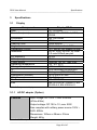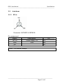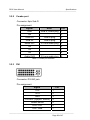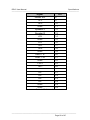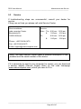
1
RD15 User Manual ————————————————————————— User Manual Display RD15 ————————————————————————— RD15 User Manual ————————————————————————— ————————————————————————— Page 2 of 47 RD15 User Manual ————————————————————————— roda computer GmbH Landstrasse 6 77839 Lichtenau/Baden Telefon: +49(0)7227/9579-0 Telefax: +49(0)7227/9579-20 roda Service Center Hüllhorst Bredenhop 20 32609 Hüllhorst Telefon: +49(0)5744/944-470 Telefax: +49(0)5744/944-475 ————————————————————————— Page 3 of 47 RD15 User Manual ————————————————————————— No part of this publication may be reproduced, transmitted, transcribed, stored in a retrieval system, or translated into any language, or computer language, in any form, or by any means, electronic, mechanical, magnetic, optical, chemical, or other, without the prior written permission of the manufacturer. The manufacturer reserves the right to revise this publication and to make changes to the contents hereof without obligation to notify any person of such revision or changes. The manufacturer makes no representations or warranties, either expressed or implied, with respect to the contents hereof and specifically disclaims any warranties as to merchantability or fitness for any particular purpose. Any of the software described in this manual is sold or licensed "as is". Should the programs prove defective following purchase, the buyer (and not the manufacturer, its distributor, or its dealer), assumes the entire cost of all necessary servicing, repair and any incidental or consequential damages resulting from any software defects. Copyright © 2011 roda computer GmbH Lichtenau, 2011-02-15 Author: Christian Fessler Version History: Version Description Date Written by 1.0 Created 15.02.11 C. Fessler 1.1 Removed PIP option 21.02.11 C. Fessler 1.2 Revised version 24.02.11 C. Fessler 1.3 OSD menu PD/SD renamed 09.03.11 C. Fessler ————————————————————————— Page 4 of 47 RD15 User Manual ————————————————————————— Trademark Acknowledgments All product and company names are trademarks or registered trademarks of their respective holders. ————————————————————————— Page 5 of 47 RD15 User Manual ————————————————————————— Conventions This manual is divided into individual chapter with interdependent contents. If you have experience with the use of computers and/or displays, you may skip individual chapters or directly look up the respective keywords. Pictures and tables are numbered consecutively. Keys and key combinations are written in square brackets, e.g., [Ctrl]+[Alt]+[F1] means that you must press Control, Alt and F1 keys simultaneously. Note Notes contain important information in connection with the directly related text or chapter. Attention You will find Attention notes where data loss or display damage may be the result of non-compliance with this note. Warning Warnings inform you that personal damage or damage to the display or individual components thereof may be the consequence or carelessness or non-compliance with the respective warning. ————————————————————————— Page 6 of 47 RD15 User Manual ————————————————————————— Regulatory information / Disclaimers Installation and use of this RD15 must be in strict accordance with the instructions included in the user documentation provided with the product. Any changes or modifications (including the antennas) made to this device that are not expressly approved by the manufacturer may void the user’s authority to operate the equipment. The manufacturer is not responsible for any radio or television interference caused by unauthorized modification of this device, or the substitution of the connecting cables and equipment other than manufacturer specified. It is the responsibility of the user to correct any interference caused by such unauthorized modification, substitution or attachment. Manufacturer and its authorized resellers or distributors will assume no liability for any damage or violation of government regulations arising from failing to comply with these guidelines. ————————————————————————— Page 7 of 47 RD15 User Manual ————————————————————————— Note: Descriptions made in this manual are done for standard RD15. Depending on costumers configuration your device may vary. CE Products with the CE Marking comply with both the EMC Directive (2004/108/EC) and the Low Voltage Directive (2006/95/EC) issued by the Commission of the European Community. Compliance with these directives implies conformity to the following European Norms: EN 55022 ( CISPR 22 ) Radio Frequency Interference EN 55024 ( EN61000-4-2, EN61000-4-3, EN61000-4-4, EN61000-45, EN61000-4-6,EN61000-4-8,EN61000-4-11,EN61000-3-2, EN61000-3-3) Generic Immunity Standard LVD EN 60950 ( IEC950 ) Product Safety, IEC 60950-1:2005 Recycling All materials used in the construction of this unit are recyclable or environmentally friendly. Please recycle the packing materials, and at the end of the computer's life, all other materials in accordance with the local regulations. Please refer “Material and Recycling” for the contents of the materials. ————————————————————————— Page 8 of 47 RD15 User Manual ————————————————————————— Note: The equipment may still contain tiny amount of hazardous substances for health and environment, though those are below control level. To avoid spreading such substances into the eco system, and to minimize the pressure on the environment, you are encouraged to use the appropriate take-back for reusing or recycling most of the materials in a safe way after the service life. The crossed bin symbol indicates proper disposal is required. For more information on collection, reuse and recycling, please consult the local or regional waste administration for more information. ————————————————————————— Page 9 of 47 RD15 User Manual Table of contents —————————————————————————— Table of contents 1 1.1 1.2 1.2.1 1.2.2 1.2.3 1.2.4 1.2.5 1.3 Getting Started ....................................................................... 14 Introduction............................................................................. 14 View ........................................................................................ 16 Front view ............................................................................... 16 Rear view................................................................................ 17 Connector panel ..................................................................... 17 Left/right side view.................................................................. 18 Top side view.......................................................................... 19 Preparing the RD15................................................................ 19 2 2.1 2.2 2.3 2.3.1 2.4 2.5 2.6 2.7 Components and Operations ................................................. 21 Location .................................................................................. 21 Ruggedness ........................................................................... 21 Displays power supply............................................................ 21 AC/DC adapter ....................................................................... 22 Power down............................................................................ 22 Interfaces................................................................................ 23 Keyboard ................................................................................ 24 Touch screen.......................................................................... 24 3 3.1 3.1.1 3.2 3.2.1 3.2.2 3.2.3 3.2.4 3.2.5 3.3 3.3.1 3.3.2 3.3.3 4 4.1 4.2 4.3 4.4 4.5 Specifications ......................................................................... 26 Display.................................................................................... 26 AC/DC adapter (Option) ......................................................... 26 Interfaces................................................................................ 27 DC-In ...................................................................................... 27 Combo port............................................................................. 28 DVI.......................................................................................... 28 VGA/RGB analog ................................................................... 30 USB 2x ................................................................................... 31 Environmental and EMI rating ................................................ 32 MIL-STD-810F........................................................................ 32 MIL-STD-461E........................................................................ 32 VG95373 ................................................................................ 32 OSD Menu.............................................................................. 34 Setup ...................................................................................... 34 Information.............................................................................. 35 Saturation ............................................................................... 35 OSD Position .......................................................................... 35 Firmware................................................................................. 36 —————————————————————————— Page 10 of 47 RD15 User Manual Table of contents —————————————————————————— 4.6 4.7 4.8 4.9 4.10 4.11 4.12 Gamma ...................................................................................36 Size .........................................................................................36 ADC (only VGA (RGB) analog mode).....................................36 Save mode ..............................................................................37 Sharpness ...............................................................................37 Contrast...................................................................................37 Brightness ...............................................................................37 5 5.1 5.2 5.3 5.3.1 5.3.2 Maintenance and Service .......................................................39 Cleaning ..................................................................................39 Troubleshooting ......................................................................39 Service ....................................................................................40 Service Supply Note: ..............................................................41 Downloads ..............................................................................42 Annex ................................................................................................44 Annex A: List of abbreviations .............................................................44 Annex B: Table of power supply connectors for different countries ....45 Annex C: List of figures........................................................................46 Annex D: List of tables .........................................................................46 ————————————————————————— Page 11 of 47 RD15 User Manual Table of contents —————————————————————————— ————————————————————————— Page 12 of 47 RD15 User Manual Getting Started CHAPTER1 —————————————————————————— Getting Started —————————————————————————— Page 13 of 47 RD15 User Manual Getting Started —————————————————————————— 1 1.1 Getting Started Introduction The multi functional 15“ XGA display RD15 with a XGA Resolution of 1024 x 768 pixels allows operation under extreme environmental conditions. It was designed according to MIL-STD 810F and offers maximum protection against shock, vibration, dust and humidity. You can find detailed information in chapter 3 Specifications. You can also set the brightness of the keyboard. It can be changed together with backlight brightness. The ON/OFF button also shuts ON/OFF devices with DP-DVI (MilDef RT/RK/RF) if connected with a DVI cable. To avoid shutting ON/OFF the display and any DP-DVI device by mistake, the ON/OFF button features a delayed circuit. The ON/OFF button must be pressed for around 5 seconds in order to shut the system ON/OFF. The display unit is equipped with a sun light readable resistive touch screen with circular polarizer, a USB keyboard with 8 function keys (F1F8), stereo amplifier with 2 speakers and an integrated 2port USB hub to connect additional USB hardware. The roda RD15 has signal input devices for DVI and RGB analogue. The signal sources can be chosen by the On Screen Display (OSD). Representation can be in 1:1 (scaled) or it can be in the usual resolutions like 640x480, 800x600 and 1024x768. The RD15 is equipped with a foil keyboard with backlight and a mouse joystick with left and right mouse button. Signal inputs The display has connectors for DVI and VGA (RGB) signal. Primary signal source (DVI/VGA) will be selected automatically. ————————————————————————— Page 14 of 47 RD15 User Manual Getting Started —————————————————————————— Please use this list to check the package contents for completeness. Contact dealer if one or more of the following listed items are not contained in the package. Please note: most accessories are optional and not part of RD15 standard delivery. External AC/DC adapter (optional) VGA (RGB) cable (optional) DVI cable (optional) Customized accessories (optional) Utility CD RD15 display (always part of delivery) Figure 1: Display ————————————————————————— Page 15 of 47 RD15 User Manual Getting Started —————————————————————————— 1.2 1.2.1 View Front view Figure 2: Front view Figure 3: Foil keyboard From left to right: Left mouse button: Executes left mouse click Mouse joystick: Moves mouse button Right mouse button: Executes right mouse click F1-F8: Function keys Key: Toggle function Brightness down: Display backlight brightness down Brightness up: Display backlight brightness up Power ON/OFF: Display power ON/OFF (with DP-DVI: notebook + display power ON/OFF) [Brightness down] + [Brightness up] = Display + keyboard backlight ON/OFF immediately [Key] + [Brightness down/up] = Keyboard backlight brightness down/up ————————————————————————— Page 16 of 47 RD15 User Manual Getting Started —————————————————————————— 1.2.2 Rear view Figure 4: Rear view 1.2.3 Connector panel DC-In Combo Port DP-DVI VGA USB USB Figure 5: Connector panel Name DC-In Combo Port Function Power supply Combo Port Connector type 3pin VG96912A8-98 PN 9pin Sub-D jack DP-DVI VGA (RGB) USB 2x DVI / Combo VGA/RGB-Analog USB Full Speed Downstream DVI-AD jack 15pin Sub-D-HD jack USB A jack Table 1: Connector panel ————————————————————————— Page 17 of 47 RD15 User Manual Getting Started —————————————————————————— 1.2.4 Left/right side view Figure 6: View left/right Figure 7: View left/right volume up/down ————————————————————————— Page 18 of 47 RD15 User Manual Getting Started —————————————————————————— 1.2.5 Top side view Figure 8: Top side view (OSD buttons) 1.3 Preparing the RD15 Unpack RD15. Add any mounting devices if applicable. Screws are not a part of standard delivery. Fasten the screws carefully. Damaging the screw threads may be a result of you put too much pressure in the screws. Connect the line cable with the power-supply unit and plug the plug into the electrical outlet. Plug the DC plug of the powersupply unit into the DC input of the RD15 and lock the connector well clockwise. Note: The enclosed line cable complies with the specifications of the country in which the display was purchased. Please ensure that the line cable has been approved for the country in which the display will be used. Find further information on country-specific power plug version in the Annex. Connect VGA or DVI with your computer. Then connect your computer with your display using the VGA/DVI cable. Turn your display ON using the power button. If the display shows the message “No signal” activating the corresponding signal source might be necessary. Depending on your used signal source, this can be done via software or hardware settings. The graphical output during POST can vary and depends on BIOS settings. It is possible that you need to boot up an operating system in order to use your display. ————————————————————————— Page 19 of 47 RD15 User Manual Components and Operations CHAPTER2 —————————————————————————— Components and Operations —————————————————————————— Page 20 of 47 RD15 User Manual Components and Operations —————————————————————————— 2 Components and Operations 2.1 Location A clean and moisture-free environment is preferred. Make room for air circulation. Avoid areas with: Sudden or extreme changes in temperature. Extreme heat. Strong electromagnetic fields (near television set, motor rotation area, etc.). Dust or high humidity. If it is necessary to work in a hostile environment, please regularly maintain your display by cleaning dust, water, etc. to keep it in optimal condition. 2.2 Ruggedness The display is designed with rugged features as vibration, shock, dust, and rain/water protection. However, it is still necessary to provide appropriate protection while operating in harsh environments. NEVER immerse the display completely in water. Doing so may cause permanent damages. Drop may cause parts break or permanent damages. The I/O ports and devices must have caps tightly closed or cable inlets sealed while exposed to water or dust. All connectors will corrode if exposed to water or moisture. Corrosion is accelerated if the power is ON. Please take proper measures in cable connection to avoid water entering into connectors. The DC jack and cables are sealed and may be operated with water splashing while attached. All port covers should be in place when no cable is attached. 2.3 Displays power supply You can power the display via AC/DC adapter. ————————————————————————— Page 21 of 47 RD15 User Manual Components and Operations —————————————————————————— 2.3.1 AC/DC adapter Figure 9: AC/DC adapter (design may vary) The enclosed mains adapter automatically adjusts to the line voltage of the respective country. Make sure you have the correct country-specific power-plug version (see Annex B). For power supply, only use original manufacturer parts provided for this display. Otherwise you may cause damage to the display and/or externally connected peripherals. Moreover, the manufacturer’s warranty will forfeit if you ignore these instructions. 2.4 Power down To power down the display, press the power button. ————————————————————————— Page 22 of 47 RD15 User Manual Components and Operations —————————————————————————— 2.5 Interfaces The standard RD15 display is equipped with several interfaces: USB 2 USB 2.0 interfaces. Those interfaces a standard USB 2.0 interfaces and are USB 1.1 compatible. VGA (RGB) You can use a VGA cable to connect to any standard VGA source. DP-DVI You can connect any single link DVI signal source with the DP-DVI interface. Additional you can connect MilDef DP-DVI signal sources to use DVI, USB and Remote ON/OFF function. Don’t use a dual link signal source together with a dual link DVI cable and a DP-DVI interface. This can cause malfunctions and damages. Use a single link DVI cable instead. DC-In (power supply) DC connecter for AC/DC adapter. Only use this interfaces with the devices designed to be connected to DC-In Interface. Combo Port Connect a Combo port cable with the Combo port and a non DP-DVI notebook to use USB and line in functionality. Don’t use a Combo port cable and simultaneously. Use a VGA (RGB) cable instead. DVI cable ————————————————————————— Page 23 of 47 RD15 User Manual Components and Operations —————————————————————————— 2.6 Keyboard Front horizontal (left to right) 1 F1 2 F2 3 F3 4 F4 5 F5 6 F6 7 F7 8 F8 9 Key 10 Brightness Down 11 Brightness Up 12 Power ON/OFF RD15 Top – OSD menu (left to right) 1 Exit Menu/Submenu 2 Menu navigation left / Reduce value 3 Menu navigation right / Increase value 4 Enter Left side volume (top down) 1 Volume up 2.7 2 Volume down Touch screen Use a stylus pen to handle the touch screen. Operating the touch screen with your fingers may contaminate the touch screen und decrease the quality. In order to use the touch screen, the touch screen drivers have to be installed on the connected computer. At ambient temperatures > 65°C pillowing is possible. This is a normal behavior and reversible as soon as the temperature is reducing. You can still operate the touch screen though. ————————————————————————— Page 24 of 47 RD15 User Manual Specifications CHAPTER3 —————————————————————————— Specifications —————————————————————————— Page 25 of 47 RD15 User Manual Specifications —————————————————————————— 3 Specifications 3.1 Display Component Size Resolution (max.) Luminance Contrast Reaction time Angle of view Displayable Colors Interfaces H-Frequency V-Frequency Power supply Operating temperature Storage temperature IP Color Dimensions (WxHxD) Weight Environment EMI Display RD15 15” (31.8 cm) XGA 1024 x 768 Pixel, VGA, SVGA typ. 250 cd/m2 480:1 25ms ton/toff Horizontal, vertical: 160° 16.7 Mio or 256 shades of gray DC-In, VGA, DP-DVI, 2x USB 2.0 max 500mA per port 60 Hz 60 Hz Nominal 19V DC, max 30W -32° to + 55°C -40° to + 80°C IP54 according to EN60529 Nato green (RAL6031HR) 351 x 300 x 57 mm Ca. 3.5 kg MIL-STD 810F MIL-STD 461E, VG95373, EN 61000-4-2, EN 61000-4-3 Table 2: Components display 3.1.1 AC/DC adapter (Option) Features Input voltage: AC 100V ~ 240V 50/60Hz (47Hz~63Hz) Output voltage: DC 19V ± 1V, max. 90W Also complies with military power source 100V ~ 240V 400Hz Dimensions: 160mm x 58mm x 30mm Weight: 650g Table 3: AC/DC adapter ————————————————————————— Page 26 of 47 RD15 User Manual Specifications —————————————————————————— 3.2 3.2.1 Interfaces DC-In Connector: SJT00RT-8-33PN014 Pin assignment: Signal 19V DC Description Power supply 19V 1/A GND GND 2/B n/c Pin 3/C Table 4: DC-In interface Note: 19V nominal voltage ————————————————————————— Page 27 of 47 RD15 User Manual Specifications —————————————————————————— 3.2.2 Combo port Connector: 9pin Sub-D Pin assignment: Signal GND Note USB A, Audio plug n/c Pin 1 2 USB IN+ USB A plug 3 USB IN- USB A plug 4 Audio IN L n/c 3.5 mm audio plug 5 6 n/c 7 n/c 8 Audio IN R 3.5 mm audio plug 9 Table 5: Combo port interface 3.2.3 DVI Connector: DVI-AD jack Pin assignment: Signal TX2- 1 Pin TX2+ 2 GND 3 PWRSW (Syspwr. Switch) Heater sense 4 5 DDC CLK 6 DDC Data 7 ————————————————————————— Page 28 of 47 RD15 User Manual Specifications —————————————————————————— Signal Heater SW Pin 8 TX1- 9 TX1+ 10 GND 11 Speaker L Speaker R 12 13 +5V 14 GND 15 +5V 16 TX0- 17 TX0+ GND 18 19 USB1 TX- 20 USB1 TX+ 21 GND 22 TXC+ 23 TXC- 24 n/c C1 n/c C2 n/c C3 n/c C4 GND GND C5 C6 Table 6: DP-DVI interface ————————————————————————— Page 29 of 47 RD15 User Manual Specifications —————————————————————————— 3.2.4 VGA/RGB analog Connector: 15pin Sub-D Pin assignment: Signal Red Green 1 2 Pin Blue 3 GND 4 GND 5 GND 6 GND GND 7 8 GND 9 GND 10 GND 11 SDA (DDC serial data) 12 BHSYNC BVSYNC 13 14 SCL (DDC data clock) 15 Table 7: VGA (RGB) interface ————————————————————————— Page 30 of 47 RD15 User Manual Specifications —————————————————————————— 3.2.5 USB 2x 1 4 Connector: USB A jack Pin assignment: Signal VCC Pin 1 USB- 2 USB+ GND 3 4 Table 8: USB interface ————————————————————————— Page 31 of 47 RD15 User Manual Specifications —————————————————————————— 3.3 3.3.1 Environmental and EMI rating MIL-STD-810F Item Criteria Temperature According to MIL-STD-810F, Method 501.4 and 502.4, Vibration According to MIL-STD-810F, Method 514.5 Category 20, Procedure I, II Procedure 1, Figure 514.5C-3 Shock According to MIL-STD-810F, Method 516.5 Procedure I 15g, 3ms 100 shocks vertical half sine 100g, 0.5ms 2 shocks per axis, half sine 25g, 6ms 3 shocks per axis, half sine Table 9: MIL-STD-810F 3.3.2 MIL-STD-461E Item MIL-STD-461E Table 10: MIL-STD-461E 3.3.3 Criteria CE101, CE102, RE102, CS101, CS114, CS115, RS103 VG95373 Item VG95373 Criteria LA01G, SA02G, SA04G, SF03G, LF01G, LF02G, LF03G, LG07G Table 11: VG95373 ————————————————————————— Page 32 of 47 RD15 User Manual OSD Menu CHAPTER4 —————————————————————————— OSD Menu —————————————————————————— Page 33 of 47 RD15 User Manual OSD Menu —————————————————————————— 4 OSD Menu Press any OSD menu button to enter OSD main menu. You can navigate with the up down buttons. Select sub menu with enter. You can exit sub menus and main menu with the escape button. Note: If there are no inputs for 20 seconds, OSD menu will exit itself automatically. To save changed values you must execute the “Save mode” function. Note: Pressing Enter button and up button simultaneously will reset OSD settings to factory values. Main menu and sub menus functions: Navigate Up/down buttons Select Enter button Exit Escape button Adjust or toggles values with the up/down buttons. 4.1 Setup Function Description PD_SOURCE Select PD source: VGA (RGB), DVI Select PD output format: All timings of timing table VGA_60, SVGA_60,... PD_OUTPUT Table 12: OSD setup ————————————————————————— Page 34 of 47 RD15 User Manual OSD Menu —————————————————————————— 4.2 Information No input possible. Function Description Display Single / dual Format, i.e. RGB Display type, i.e. DIS-2 Source, i.e. Video_1 Input timing Output window Source, i.e. Video_1 Input timing Size PD SD Table 13: OSD information 4.3 Saturation Function Description Default SATURATION Set saturation Values: 0 – 255 Value 0 = black/white 64 Table 14: OSD saturation 4.4 OSD Position Function Description OSD H POS OSD V POS OSD AUTO ALPHA Change horizontal OSD position Change vertical OSD position Center OSD Alpha-value of OSD Non transparent: 31 Transparent: 0 Table 15: OSD position ————————————————————————— Page 35 of 47 RD15 User Manual OSD Menu —————————————————————————— 4.5 Firmware No input possible. Function Description Not used Table 16: OSD firmware 4.6 Gamma Function Description Default GAMMA Set Gamma values. Values: off, 1 to 7 off Table 17: OSD Gamma 4.7 Size Function Description PD_H_SIZE PD_V_SIZE PD_H_POS PD_V_POS PD_H_CAP PD_V_CAP Change horizontal size PD Change vertical size PD Change horizontal position PD Change vertical position PD Change horizontal capture value PD Change vertical capture value PD Table 18: OSD size 4.8 ADC (only VGA (RGB) analog mode) Function Description PHASE CLOCK Set phase, values: 0 – 31 Set AD transformer sampling rate Values: sampling rate +/- 120 Table 19: OSD ADC ————————————————————————— Page 36 of 47 RD15 User Manual OSD Menu —————————————————————————— 4.9 Save mode Function Description SAVE MODE Save changes. Table 20: OSD save mode 4.10 Sharpness Function Description Default SHARPNESS Sharpness ON/OFF off Table 21: sharpness 4.11 Contrast Function Description Default CONTRAST Set contrast. Values: 0 – 255. 62 Table 22: OSD contrast 4.12 Brightness Function Description Default BRIGHTNESS Set digital brightness (no backlight!) Values: 0 – 255. 130 Table 23: OSD brightness ————————————————————————— Page 37 of 47 RD15 User Manual Maintenance and Service CHAPTER5 —————————————————————————— Maintenance and Service —————————————————————————— Page 38 of 47 RD15 User Manual Maintenance and Service —————————————————————————— 5 Maintenance and Service 5.1 Cleaning ALWAYS turn OFF the power, unplug the power cord and remove the battery before cleaning. The exterior of the system and display may be wiped with a clean, soft, and lint-free cloth. If there is difficulty removing dirt, apply non-ammonia, non-alcohol based glass cleaner to the cloth and wipe. An air gun is recommended for cleaning water and dust. For salty water please clean with fresh water then blow-dry with an air gun. Be sure not to turn the display up side down while there is water being applied. 5.2 Troubleshooting Should the display fail to function properly, the troubleshooting steps below may be followed. Check AC/vehicle adapter, battery, and the power source. Minimize the configuration, i.e., remove extra peripherals and devices. Check OSD Settings (i.e. brightness settings) Remove the software suspected. Set BIOS fail-safe default. Re-install operating system and application software. ————————————————————————— Page 39 of 47 RD15 User Manual Maintenance and Service —————————————————————————— 5.3 Service If troubleshooting steps are unsuccessful, consult your dealer for service. If they can not help you please call roda Service Center. Service address: Service: roda computer Center Mon – Thu 8:30 am - 12:30 pm Bredenhop 20 32609 Hüllhorst & Fri 1:00 pm - 4:30 pm 8:30 am - 12:30 pm & 1:00 pm - 3:00 pm Phone.: +49 5744-944 470 Fax: +49 5744-944 475 E-Mai: [email protected] Note: The roda Service Center needs a detailed description of the problem and the serial number of the device. If it is necessary to send in your computer for repairs, you can download a service waybill (Service Supply Note) on the roda homepage (www.roda-computer.com), which you have to fill in. ————————————————————————— Page 40 of 47 RD15 User Manual Maintenance and Service —————————————————————————— 5.3.1 Service Supply Note: Figure 10: Service Supply Note Include this sheet with the following information: Name Address Serial number, Customer number, Article number Place and date of purchase or the original invoice number Date of failure A DETAILED description of the problems you have encountered A list of the hardware/ software configuration, if applicable ————————————————————————— Page 41 of 47 RD15 User Manual Maintenance and Service —————————————————————————— 5.3.2 Downloads Check our website (www.roda-computer.com) for downloads: Updates Drivers Manuals Service Supply Note ————————————————————————— Page 42 of 47 RD15 User Manual Annex —————————————————————————— A N NEX Annex —————————————————————————— Page 43 of 47 RD15 User Manual Annex —————————————————————————— Annex Annex A: List of abbreviations A AC ADC BIOS C CD cd CE CRT CVBS DC D-sub DVI EMV EN F FCC GHz GND Hz IEC IEEE I/O IP kHz LCD LED mAh MHz OSD PC POST RD RGB TÜV UL USB Ampere (unit) Alternating Current Analog to Digital Converter Basic Input Output System Celsius (unit) Compact Disk Candela (unit) Conformité Européene Cathode Ray Tube Colour Video Blanking Signal Direct Current D-subminature (Sub-D) Digital Visual Interface Elektro-Magnetische Verträglichkeit Europäische Norm Fahrenheit (unit) Federal Communication Commision Giga-Hertz (unit) Ground Hertz International Electrotechnical Commission Institute of Electrical and Electronics Engineers Input/Output Ingress Protection Kilo-Hertz (unit) Liquid Crystal Display Light Emitting Diode Milliampere Hour (unit) Mega-Hertz (unit) On Screen Display Personal Computer Power On Self Test Ruggedised Display Red Green Blue (Video signal) Technischer Überwachungs Verein Underwriters Laboratories Universal Serial Bus ————————————————————————— Page 44 of 47 RD15 User Manual Annex —————————————————————————— V VGA W Volt (unit) Video Graphics Adapter Watt (unit) Annex B: Table of power supply connectors for different countries Version Country/region Europe Technical data 230V, 50Hz, 6A Switzerland 220V, 50Hz, 6A Great Britain 240V, 50Hz, 6A Australia 240V, 50Hz, 6A North America 120V, 60Hz, 7A Table 24: Table of power supply connectors ————————————————————————— Page 45 of 47 RD15 User Manual Annex —————————————————————————— Annex C: List of figures FIGURE 1: DISPLAY............................................................................. 15 FIGURE 2: FRONT VIEW ..................................................................... 16 FIGURE 3: FOIL KEYBOARD............................................................... 16 FIGURE 4: REAR VIEW........................................................................ 17 FIGURE 5: CONNECTOR PANEL........................................................ 17 FIGURE 6: VIEW LEFT/RIGHT............................................................. 18 FIGURE 7: VIEW LEFT/RIGHT VOLUME UP/DOWN.......................... 18 FIGURE 8: TOP SIDE VIEW (OSD BUTTONS) ................................... 19 FIGURE 9: AC/DC ADAPTER............................................................... 22 FIGURE 10: SERVICE SUPPLY NOTE................................................ 41 Annex D: List of tables TABLE 1: CONNECTOR PANEL.................................................................17 TABLE 2: COMPONENTS DISPLAY..........................................................26 TABLE 3: AC/DC ADAPTER ........................................................................26 TABLE 4: DC-IN INTERFACE......................................................................27 TABLE 5: COMBO PORT INTERFACE......................................................28 TABLE 6: DP-DVI INTERFACE ...................................................................29 TABLE 7: VGA (RGB) INTERFACE............................................................30 TABLE 8: USB INTERFACE ........................................................................31 TABLE 9: MIL-STD-810F ..............................................................................32 TABLE 10: MIL-STD-461E............................................................................32 TABLE 11: VG95373 .....................................................................................32 TABLE 12: OSD SETUP ...............................................................................34 TABLE 13: OSD INFORMATION.................................................................35 TABLE 14: OSD SATURATION...................................................................35 TABLE 15: OSD POSITION .........................................................................35 TABLE 16: OSD FIRMWARE.......................................................................36 TABLE 17: OSD GAMMA .............................................................................36 TABLE 18: OSD SIZE ...................................................................................36 TABLE 19: OSD ADC....................................................................................36 TABLE 20: OSD SAVE MODE.....................................................................37 TABLE 21: SHARPNESS..............................................................................37 TABLE 22: OSD CONTRAST ......................................................................37 TABLE 23: OSD BRIGHTNESS...................................................................37 TABLE 24: TABLE OF POWER SUPPLY CONNECTORS.....................45 ————————————————————————— Page 46 of 47 RD15 User Manual Annex —————————————————————————— ————————————————————————— Page 47 of 47