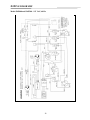
1
Protector®
Multi-Hazard Glove Box
Models 5065000, 5065002
5065500, 5065502
INSTRUCTION MANUAL
Product designs are subject to change without notice
© 2002 Labconco Corporation
50937 Rev C, ECO 9999
Printed in U.S.A.
TABLE OF CONTENTS
Introduction
Preface/Important Notices .................................................................4
Components Shipped .........................................................................5
General Description ...........................................................................6
Optional Filters ..................................................................................6
Charcoal Filters..................................................................................6
Additional Exhaust HEPA Filter Kit .................................................6
Performance .......................................................................................7
Environmental Conditions .................................................................7
Component Identification ..................................................................8
Installation ....................................................................................................11
Location .............................................................................................11
Connection Exhaust ...........................................................................11
Glove Attachment ..............................................................................11
Glove Replacement............................................................................11
Safety Precautions........................................................................................12
Normal Operation........................................................................................13
Blower Operation...............................................................................13
Routine Maintenance...................................................................................14
Estimation of Filter Condition ...........................................................14
Filter Replacement .............................................................................14
Suggested Plan for Decontamination.................................................14
Gloves ................................................................................................15
Transfer Chamber Inner and Outer Door...........................................15
Fluorescent Lamp Replacement.........................................................16
Replacement Parts .......................................................................................17
Dimensional Data .........................................................................................24
Electrical Specifications ..............................................................................25
Wiring Diagrams..........................................................................................26
Accessories ....................................................................................................28
Warranty ......................................................................................................29
Shipping Claims ...........................................................................................30
Contacting Labconco ...................................................................................31
Declaration of Conformity ..........................................................................32
PREFACE
Thank you for displaying confidence in us by selecting a Labconco Protector® MultiHazard Glove Box. Our design engineers, assemblers and inspectors have utilized their skills and
years of experience to ensure that the new Labconco Controlled Atmosphere Glove Box meets our
high standards of quality and performance.
IMPORTANT NOTICE
Labconco Protector® Glove Boxes are designed to contain chemical and some biohazardous materials. The Protector should not be considered a Class III Bio-Hazard Cabinet, nor
should they be considered for use with Biosafety Level 4 agents. While the Protector Glove Box
provides a physical barrier between the user and their work, it is the user’s responsibility to ensure
that all materials are appropriately decontaminated, inactivated, or rendered harmless before
removal from the unit. For further information regarding the handling of specific materials, please
contact your facilities safety officer.
All the end users should read this manual carefully in order to become familiar with the
operation of the glove box. Recommendations are made within the manual to help you obtain
maximum performance and life from your product.
We have included sections on initial set up, operation, maintenance and troubleshooting to
provide you with all the tools necessary to achieve maximum performance.
If you have questions or concerns, do not hesitate to call us at 1-800-821-5525 for
assistance.
4
INTRODUCTION
Components Shipped
Carefully check the contents of the carton for damage that might have occurred in transit.
Do not discard the carton or packing material until all components have been checked against the
following component list and the equipment has been installed and tested.
As shipped, the carton should contain the following:
Part Number
5065000
or
5065500
Description
Multi-Hazard Glove Box, Fiberglass
Multi-Hazard Glove Box, Stainless Steel
5005600
Glove Kit – Pair, Neoprene, size 9-3/4
(includes 2 - O-Rings)
5093700
Instruction Manual
5
INTRODUCTION
General Description
The Multi-Hazard Glove Box is equipped with a blower, air damper and filter system that
provide versatility for many particular applications. The variable speed blower provides air
volumes between 10 and 50 CFM and negative glove box pressure up to 1.5 inches H2O
gauge. The air damper provides a means for operating the glove box at a more negative
pressure when the blower is running at low speed (low air volume). The filtering system
consists of one inlet HEPA and one exhaust HEPA filter (both rated at 99.99% efficient on
0.3 micron particulates). A “roughing” prefilter is also provided to capture room air
particles and extend the life of the inlet HEPA filter.
Optional Filters: (for installation between exhaust HEPA and blower).
Charcoal Filter: (Cat. No. 5065300) contains 4 lbs. of Barnebey and Sutcliffe type 787
impregnated, activated carbon for removal of gaseous radioisotopes.
Additional Exhaust HEPA Filter Kit (Cat. No. 5065200) same as filter shipped with unit,
plus an extended length tube for connection to blower.
Figure 1
6
INTRODUCTION
Performance
The Labconco Protector Multi-Hazard Glove Box has been carefully designed, constructed
and tested in order to provide an effective physical barrier between the laboratory and the glove
box interior. This barrier and the filtering system, provides a clean air enclosure for protection of
specimens and materials. It also provides protection to the technician from contaminated materials
and specimens.
Environmental Conditions
This equipment is designed to be safe under the following conditions:
•
Indoor use
•
Altitude up to 6562 Ft. (2000m)
•
Temperature 41° to 104° (5° to 40°)
•
Maximum relative humidity 80% for temperatures up to 88°F (31°C) decreasing linearly to
50% relative humidity at 104° (40°C)
•
Main supply voltage fluctuations not to exceed ± 10% of the nominal voltage
•
Transient over voltages according to Installation Categories II (Over voltage Categories per
IEC 1010)
•
Pollution degrees 2 (Normally only non-conductive foreign matter, solid, liquid, or gaseous
(ionized gases), that may produce a reduction of dielectric strength or surface resistivity
occurs. Occasionally, however, a temporary conductivity caused by condensation must be
expected), in accordance with IEC 664
7
INTRODUCTION
Component Identification
General components of the glove box are listed below and identified in Figure 2.
1. Glove Ports. Epoxy coated aluminum, 8" ID, spaced 17" apart, sealed to viewing window
with one-piece molded neoprene gasket. Supplied with dual O-ring grooves, neoprene
gloves, and retaining O-rings.
2. Neoprene Gloves. Supplied with the glove box, gloves are .015" thick neoprene, 30" long,
one pair, and size 9-3/4. (Note: For replacement gloves, see Replacement Parts on page
18.
3. Window Frame. 12-gauge epoxy coated steel, attached with 30 stainless steel, ¼-20
screws, removable for full access to the interior.
4. Viewing Window. 3/8" thick laminated safety glass, mounted at 10° angle and sealed with
one-piece molded neoprene gasket. Optional 3/8" thick polycarbonate with abrasion
resistant coating available. See page 18.
5. Left Side Panel. 20-gauge epoxy coated steel, easily removable for access to glove box
and left electrical outlet.
6. Fluorescent Lamp. 30 watts provides minimum of 60-foot candles illumination to interior
work surface. Supplied with electrical cord and plug, the lamp may be easily removed for
bulb replacement and for access to removable viewing window. For lamp replacement see
page 16.
7. Façade. 18-gauge, epoxy coated steel, conceals filter damper, and blower.
8. Control Panel. Contains gauge for glove box pressure and switches for fluorescent lamp,
interior receptacles, blower power, and blower speed control.
9. 115 Volt, 3-Wire Receptacles (Models 5065000 and 5065500). One right and one left
interior receptacle, 9 amps combined rating. Exterior switches provide separate control of
each receptacle.
230 Volt, 3-Wire Receptacles (Models 5065002 and 5065502). One right and one left
interior receptacle, 8 amps combined rating. Exterior switches provide separate control of
each receptacle.
10. Transfer Chamber Door. Counterweighted with quick operating latch.
8
INTRODUCTION
Figure 2
9
INTRODUCTION
Airflow system components are listed below and are identified in Figure 3.
1. Inlet Pre-Filter. Polyester fiber mat filter captures larger room air particles to extend life
of inlet HEPA filter.
2. Air Damper. Adjust fully open (parallel with air flow) for maximum airflow volume.
Adjust toward closed position to increase glove box negative pressure differential (if
desired) when operating blower at low speed.
3. Inlet HEPA Filter. Rated 99.99% efficient on 0.3-micron particulates. NOTE: Inlet and
exhaust filters are identical. Airflow direction is indicated on the filter.
4. Exhaust HEPA Filter. Rated 99.99% efficient on 0.3-micron particulates.
5. NOTE: Unit is normally supplied with a removable tube at this location which can easily
be replaced with either of the two following optional filters:
Charcoal Filter (Cat. No. 5065300) contains 4 lbs. of Barnebey and Sutcliffe type 787
impregnated carbon (for removal of gaseous radioisotopes).
Additional Exhaust HEPA Filter Kit (Cat. No. 5065200)
6. Blower. Adjustable speed (control is located on front control panel) provides airflow
between 10 and 50 CFM. The discharge opening measures 3 inch square.
Figure 3
10
INSTALLATION
Location
Glove box should be placed on a stable, level base stand near an appropriate electrical
receptacle. The base stand must be capable of supporting 500 lbs minimum, and the height should
provide a comfortable working position through glove ports (normally 35" to 37" height for
standing position).
Connections, Exhaust
NOTE: It is the user’s responsibility to determine if the exhaust should be vented to
outside the building. If it is ducted to the outside, duct restrictions should not exceed 0.5 inches
water gauge static pressure at 50 CFM.
Glove Attachment
With glove thumbs up and right/left orientation, secure the gloves in place on the glove
ports by stretching the beaded glove cuff into the groove nearest the window. Install the 8"
diameter O-ring onto the outer groove over the glove surface.
Figure 4
Glove Replacement
If it becomes necessary to change gloves without disturbing the integrity of the glove box
environment, follow these steps:
1. Remove the O-ring from the old glove.
2. Roll the old glove cuff bead from the inner groove nearest the window to the outside
groove.
3. Insert the new glove through the old glove until the fingers of both are inside the glove box.
4. Stretch the new glove’s beaded cuff over the old glove cuff and into the groove nearest the
window.
5. To remove the old glove, grasp the new glove surface and manipulate the old glove bead
free from the outer groove.
6. With the other glove hand inside the box, pull the old glove into the glove box.
7. Install the O-ring over the new glove onto the outer groove.
11
SAFETY PRECAUTIONS
•
This product is neither designed nor intended to be an explosion-proof enclosure. It
is the responsibility of the user to determine the lower explosive limits and
flammability of the enclosed gases and other matter. The user is also responsible
for using proper precautions to prevent equipment damage or injury due to
explosion or combustion.
•
It is the responsibility of the user to determine the suitability of this product for the
intended applications.
12
NORMAL OPERATION
Start Up
NOTE: All internal wiring is protected by two manual reset circuit breakers located on the
rear panel.
•
Confirm that the glove box electrical power cord is plugged into an appropriate
electrical power source.
•
Switch on the fluorescent lamp and check to make sure bulb is working.
•
Connect a test light to each interior receptacle and check for proper operation by
turning on the left and right outlet switches located on the control panel.
•
Turn on the blower switch and check blower operation.
NOTE: This should be done with gloves installed so that glove box negative pressure will
be induced (observed by gauge on control panel). If the blower speed control is adjusted in
the low range, you will notice that the blower starts at a higher speed, then slows down.
•
If unit is vented to the outside, confirm that ducting is sealed properly for positive
pressure operation.
Blower Operation
The blower is operated on and off by a switch located on the control panel. The speed of
the blower is regulated from 10% to 100% of maximum speed. Normal operation will be in the
30% to 50% area, depending on filter loading conditions and desired negative pressure within the
enclosure. It may be necessary, during continued operation to increase the blower speed to
compensate for possible restrictions to air flow caused by a dirty filter. The static pressure setting
should be within .25 to .5 H2O. Pressure settings higher than this may cause excessive air flow,
and are disruptive to operations within the enclosure.
13
ROUTINE MAINTENANCE
Estimation of Filter Condition
The negative pressure inside the box will give a good indication of filter and system
condition. Set blower speed dial to the speed that gives the proper negative pressure conditions
inside the box. Record both the blower speed dial setting and the pressure reading on the gauge.
If box pressure begins to drop due to filter loading, increase the blower speed. To check filters,
reduce the blower speed dial setting to the setting recorded when the filters were clean. Read the
differential pressure gauge. When the gauge reading is one-half of the initial reading, replace
filters.
Filter Replacement
When filters become contaminated or after a predetermined length of time in use, the filter
should be replaced. Only experienced personnel, competent in the procedure of filter replacement
should perform this procedure.
Suggested Plan for Decontamination
Activities such as filter changing, service work, moving the cabinet, or gross spillage
generally require a gas decontamination procedure.
ONLY EXPERIENCED PERSONNEL COMPETENT IN THIS
PROCEDURE SHOULD BE USED.
LABCONCO strongly recommends reference to the Laboratory Safety Monograph (a
supplement to the NIH Guidelines for Recombinant DNA Research), published by the U.S.
Department of Health, Education and Welfare, January 1979.
Reference may also be made to the Formaldehyde Decontamination booklet available from
the U.S. Department of Health, Education and Welfare, Public Health Service, National Institute of
Health, National Cancer Institute.
For decontamination procedures with formaldehyde, refer to the following information.
1. NCI Safety Standards for Research Involving Chemical Carcinogens. Publication No.
(NIH) 76-900, 1975.
2. Carcinogen Safety Monographs, NCI Office of Research Safety.
3. “Potential Hazard of Tissue Culture Assays Arising from Carcinogenic Compounds
Incompletely Removed by Washing” E. B. Sansone, J. A. Poiley, R. J. Pienta and W. B.
Lebberz, III, Cancer Research 36.2455 – 1976.
4. “Recommended Decontamination Procedures for Aflatoxin”, L. Stoloff and W. Trager.
Journal of the Association of Official Agricultural Chemists, 48.681 – 1965.
14
ROUTINE MAINTENANCE
Gloves
At least every three months (more often if subjected to heavy use), inspect the gloves for
signs of damage or wear. For replacement, refer to page 11.
Transfer Chamber Inner and Outer Door
Periodically check the closing tension of the door latches. Closing the latch handle should
require some firm force, indicating compression of the door seals. Seals, compression, and
latching force can be adjusted as follows:
1. Close and latch the door.
2. Using a 1/2" open-end wrench, turn the door adjustment screw (located between the door
and the latch bar) clockwise to increase seal compression and latching force. Turn screw
counterclockwise to decrease compression. Refer to figure 5.
Figure 5
15
ROUTINE MAINTENANCE
Fluorescent Lamp Replacement
1. Turn the light switch off and unplug the lamp power cord from the receptacle located on
the outside top of the cabinet.
2. From the top of the lamp housing, remove the two Phillips screws attaching the lamp
assembly to the top edge of the window frame.
3. Remove the lamp assembly from the unit.
4. The lamp tube can then be easily removed and replaced. Replacement lamp part #12779
(fluorescent lamp) #F30T12/CW/RS may be purchased from most local lighting supply
stores.
5. Re-install the lamp assembly and attach with the two Phillips screws. Plug in the power
cord and switch on the lamp. Refer to figure 6.
Figure 6
16
REPLACEMENT PARTS
Figure 7
17
REPLACEMENT PARTS
Ref. No.
Catalog No.
Description
1
2
3
3A
4
5066600
5066700
5067200
5098400
5005500
5
6
7
8
9
10
11
12
13
14
15
16
17
18
18A
19
20
20A
21
22
23
24
25
26
27
1640500
5005501
1640501
5005502
1640502
5005600
1640600
5005601
1640601
5005602
1640602
1640000
1952500
1329700
1301500
5092600
5064200
5098300
1928800
1928900
5065100
5065300
1490700
1490600
5094600
5109700
1327900
5094400
5104500
Glass Viewing Window
Polycarbonate Viewing Window (Optional)
Viewing Window Gasket (NOT SHOWN) – For Model 5065000
Viewing Window Gasket (NOT SHOWN) – For Stainless Steel Model 5065500
Glove Kit 8-1/2 Size Neoprene
Gloves (1 Pr.) Two O-Rings
8-1/2 Size Neoprene Gloves (1 Pr.)
Kit: 8-1/2 size Butyl Gloves (1 Pr.) 2 O-Rings
8-1/2 Size Butyl Gloves (1 Pr.)
Kit: 8-1/2 Size Hypalon Gloves (1 Pr.) Two O-Rings
8-1/2 Size Hypalon Gloves (1 Pr.)
Kit: 9-3/4 Neoprene Gloves (1 Pr.) Two O-Rings
9-3/4 Size Neoprene Gloves (1 Pr.)
Kit: 9-3/4 Size Butyl Gloves (1 Pr. ) Two O-Rings
9-3/4 Size Butyl Gloves (1 Pr.)
Kit: 9-3/4 Size Hypalon Gloves (1 Pr.) Two O-Rings
9-3/4 Size Hypalon Gloves (1 Pr.)
O-Rings (1 Pr.) for Gloves
Pressure Differential Gauge
Switch, 115V
Switch, 230V
Blower Speed Controller
Transfer Chamber Door Gasket (1 inner, 1 outer)
Transfer Chamber Door Gasket, (1 inner, 1 outer) Stainless Steel
Housing Filter
Pre-Filter
Filter, HEPA
Charcoal Filter (Optional)
Tube, Offset
Elbow – 90°
Motor – Blower Assembly
Motor Assembly
Relay
Circuit Board Assembly
Transformer Assembly (NOT SHOWN) 230V models only
28
18
REPLACEMENT PARTS
(A) Glove Port Components (Detailed on Page 19)
(B) Sealed Receptacle Components (Detailed on Page 20)
(C) Fluorescent Lamp Assembly (Detailed on Page 21)
(D) Inner Door Assembly (Detailed on Page 22)
(E) Outer Door Assembly (Detailed on Page 23)
A. Glove Ports
Ref. No.
Catalog No.
1
2
3
4
5074201
5074301
5066800
1889310
Description
Glove Port
Glove Port Mounting Ring
Glove Port Gasket
Glove Port Mounting Screw
Figure 8
19
REPLACEMENT PARTS
B. Sealed Receptacle Assembly
Ref. No.
Catalog No.
1
1A
2
3
4
5075600
5102100
1645702
1349100
1349200
Description
Sealed Receptacle, 115V
Sealed Receptacle, 230V
Receptacle O-Ring
Cupped Washer
Locknut
Figure 9
20
REPLACEMENT PARTS
C. Fluorescent Lamp Assembly (Complete with Bulb), No. 5072600
Ref. No.
Catalog No.
1
1277900
2
3
1279200
5072901
Description
Lamp Bulb #F30T12/CW/RS
(also available locally)
Lamp Fixture Assembly
Lamp Housing
Figure 11
21
REPLACEMENT PARTS
D. Inner Door Assembly,
Ref. No.
1
2
3
4
5
6
7
8
9
No. 5067700 (Used on 5065000)
No. 5098500 (Used on 5065500)
Catalog No.
(Acrylic 5067700)
Catalog No.
(Stainless Steel 5098500)
5102800
5064500
1645701
1927000
5064600
5068600
5085201
5074401
5097900
5064600
5068600
5085201
5074401
5098100
Figure 11
22
Description
Inner Door Assembly
Door Fitting
Door O-Ring
Nut, Stainless Steel ¾-16
Door Adjusting Screw
Door Clamp
Inside Latch Bar Assembly
Inside Counterweight
Grab Knob
REPLACEMENT PARTS
E. Outer Door Assembly, No. 5068400 (Used on 5065000)
No. 5098600 (Used on 5065500)
Ref. No.
Catalog No.
(Acrylic 5068400)
1
2
3
4
5
6
7
8
5102900
5064500
1645701
1927000
5064600
5068600
5085301
5074501
Catalog No.
(Stainless Steel 5098600) Description
5097500
5064600
5068600
5085301
5074501
Figure 12
23
Outer Door Assembly
Door Fitting
Door O-Ring
Nut, Stainless Steel ¾-16
Door Adjusting Screw
Door Clamp
Outside Latch Bar Assembly
Outside Counterweight
DIMENSIONAL DATA
24
ELECTRICAL SPECIFICATIONS
Electrical Specifications for both the 5065000 and 5065500 models are as follows:
115 Volts, 60 Hz, 15 Amps
One 30-Watt Fluorescent Lamp
Two 115 Volt, combined 9 Amp electrical outlets (front, left and right interior of
cabinet)
One blower motor rated 1.8 FLA, 115V
Electrical Specifications for both the 5065002 and 5065502 models are as follows:
230 Volts, 50 Hz, 10 Amps
One 30-Watt Fluorescent Lamp
Two 230 Volt, combined 8 Amp electrical outlets (front, left and right interior of
cabinet)
One blower motor rated 1.8 FLA, 115V
One transformer 230/115V
25
WIRING DIAGRAMS
Model 5065000 and 5065500 – 115 VAC, 60 Hz
26
WIRING DIAGRAM
Models 5065002 and 5065502 – 230 VAC, 50 Hz
27
ACCESSORIES
Accessory Part #
5061600
Description
Interior Storage Shelves
Three stainless steel storage shelves are attached to epoxy coated stainless
steel upright supports. Shelves are adjustable height, measuring 6" D x 30" W
x 21-1/2" H. Components may be passed through the transfer chamber and
assembled within the glove box enclosure. Installation by customer.
5062000
Glove Box Mobile Base Stand
Welded steel construction, epoxy coated with black phenolic laminate top
surface. 1-1/8" thick x 30" D x 60" W, height adjustable from 30" - 37".
Lower shelf provides convenient storage space. Accessory includes 5" swivel
casters with locking brakes.
5062001
Glove Box Stand
Same as above except furnished with adjustable leveling feet instead of
casters.
5060400
Interior Glove Port Cover
12-gauge stainless steel with molded rubber self-centering gasket and spring
loaded latches with adjustable closure knob. Use for internal sealing of glove
port in event of worn or damaged gloves.
5060500
Exterior Glove Port Cover
12-gauge stainless steel with molded neoprene self-centering gasket.
Adjustable tension knob with latching bar attaches to port mounting ring
screw adaptor.
5065300
Charcoal Filter
Filter installs between exhaust HEPA filter and blower. Contains 4 lbs. of
Barnebey and Stucliffe type 787 activated carbon impregnated for removal of
gaseous radioisotopes.
5065200
Additional Exhaust HEPA Filter Kit
Filter installs between existing exhaust HEPA and blower. Rated 99.99%
efficient on 0.3 micron particulates.
28
WARRANTY
We are committed to providing our customers with quality equipment and service after the sale.
Part of this objective involves keeping you informed of changes and new product additions. We,
therefore, request that you take a moment to fill out the product registration card so we many know
your location as well as some of the reasons that prompted you to purchase our product.
Labconco provides a warranty on all parts and factory workmanship. The warranty includes areas
of defective material and workmanship, provided such defect results from normal and proper use
of the equipment.
The warranty for all Labconco products will expire one year from date of installation or two years
from date of shipment from Labconco, whichever is sooner, except the following:
•
•
•
Purifier® Delta® Series Biological Safety Cabinets carry a three-year warranty from date
of installation or four years from date of shipment from Labconco, whichever is sooner.
Carts carry a lifetime warranty.
Glassware is not warranted from breakage when dropped or mishandled.
This limited warranty covers parts and labor, but not transportation and insurance charges. In the
event of a warranty claim, contact Labconco Corporation or the dealer who sold you the product.
If the cause is determined to be a manufacturing fault, the dealer or Labconco Corporation will
repair or replace all defective parts to restore the unit to operation. Under no circumstances shall
Labconco Corporation be liable for indirect, consequential, or special damages of any kind. This
statement may be altered by a specific published amendment. No individual has authorization to
alter the provisions of this warranty policy or its amendments. Lamps and filters are not covered
by this warranty. Damage due to corrosion or accidental breakage is not covered.
WARNING: The disposal and/or emission of substances used in connection with this equipment
may be governed by various federal, state or local regulations. All users of this equipment are
urged to become familiar with any regulations that apply in the user’s area concerning the
dumping of waste materials in or upon water, land or air and to comply with such regulations.
29
SHIPPING CLAIMS
If a shipment is received in visibly damaged condition, be certain to make a notation on the
delivering carrier’s receipt and have their agent confirm the damage on your receipt. Otherwise,
the damage claim may be refused.
If concealed damage or pilferage is discovered, notify the carrier immediately and retain the entire
shipment intact for inspection. Interstate Commerce Commission rules require that the claim be
filed with the carrier within 15 days after delivery.
NOTE: Do not return goods. Goods returned without prior authorization will not be accepted.
Labconco Corporation and its dealers are not responsible for shipping damage. Claims must be
filed directly with the freight carrier by the recipient. If authorization has been received to return
this product, by accepting this approval, the user assumes all responsibility and liability for
biological and chemical decontamination and cleansing. Labconco reserves the right to refuse
delivery of any products, which do not appear to have been properly cleaned and/or
decontaminated prior to return.
30
CONTACTING LABCONCO
If you have any questions that are not addressed in this manual, or if you need technical assistance,
please contact Labconco’s Sales Information Department at 1-800-821-5525, and Service
Information at 1-800-522-7658 or 1-816-333-8811, between the hours of 7:00 a.m. and 6:00 p.m.
Central Standard Time.
Labconco’s mailing address is:
Labconco Corporation
8811 Prospect Avenue
Kansas City, Missouri 64132-2696
Fax # 816-363-0130
Visit Labconco through the Internet at:
http://www.labconco.com
or
email: [email protected]
31
32